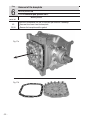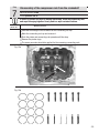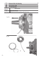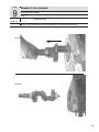
1
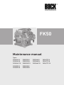
FK50
Maintenance manual
09608-09.03-DGbFEITr
Types:
FK50/460 K
FK50/460 N
FK50/460 TK
FK50/555 K
FK50/555 N
FK50/555 TK
FK50/830 K
FK50/830 N
FK50/980 K
FK50/980 N
FK50/660 K
FK50/660 N
FK50/660 TK
FK50/775 K
FK50/775 N
FK50/775 TK
-1-
Foreword
Dear Customer,
Bock compressors are top-quality, reliable, service-friendly quality products. Please comply with the
following operating and maintenance instructions so that you can benefit from all advantages to the
full and use your refrigerating system throughout its entire service life. If you have any questions about
installation, operation and accessories, please contact our technical service or your refrigerating system wholesale dealer or our representative. The Bock service team is available by phone under +49
7022 9454-0, by e-mail under [email protected] or on the internet under www.bock.de. In addition, for
German speaking countries we have set up a toll-free hotline under 00 800 / 800 000 88 from Monday
to Saturday between 8 a.m. and 9 p.m. Any suggestions you may have regarding the on-going development of our compressor, equipment and parts programme are welcome at any time.
Bock Kältemaschinen GmbH
Postfach 11 61
D-72632 Frickenhausen
Benzstr. 7
D-72636 Frickenhausen
Fon: +49 7022 9454-0
Fax: +49 7022 9454-137
[email protected]
www.bock.de
-2-
The high quality standard of Bock compressors is guaranteed
also by on-going further development of machine, features
and accessories. This could possibly result in nonconformities
between this present manual and your compressor. Please
understand that it is not possible for any claims to be derived
from the details, illustrations and descriptions.
Your team at
Bock Kältemaschinen GmbH
- Subject to modifications -
09608-09.03-DGbFEITr
Please read the information summarised for you in this manual before starting work.
It contains important instructions for safety, installation, initial commisioning and hanPlease read
the information
summarised
you in this
dling. In addition you will find information
on maintenance,
spare
parts andfor
accessories.
manual
before
starting
work.
Some instructions are identified by special symbols with the following meaning:
contains
importantthat
instructions
for safety,
installation,
initial
WARNING! This symbol isIt used
to indicate
inaccurate
compliance
or total
commissioning
and
handling.
In
addition
you
will
fi
nd
informafailure to comply with the instructions could cause injury to persons or damage
tion on maintenance,
to the comperssor or refrigerating
machine.spare parts and accessories.
Some instructions are identified by special symbols with the
DANGER! This symbol refers to instructions for avoiding direct serve dangers to
following meaning:
persons.
WARNING! This symbol is used to indicate
that inaccurate
compliance
or total
failure to
to
DANGER! This symbol refers to instrucion
for avoiding
direct serve
dangers
comply with the instructions could cause injury
persons or plant by electrical current.
to persons or damage to the compressor or
refrigerating
machine which you should
This symbol indicates important additional
instructions
DANGER!
This
symbol refers to instructions for
observe during your work.
avoiding direct severe dangers to persons.
The high quality standart of Bock compressors is guaranteed also by on-going furtherdevelopThis results
symbolinrefers
to instructions for
ment of machine, features and accessories. ThisDANGER!
could possible
non conformities
avoiding
severetha
dangers
personsforor
between this present manual and your compressor.
Pleasedirect
understand
it is nottopossible
plantand
by electrical
current.
any claims to be derived from the details, illstrations
descriptions.
This symbol indicates important additional
Your team at
instructions which you should observe during
Bock Kältemaschinen GmbH
- Subject to modification your work.
09608-09.03-DGbFEITr
Contents Introduction
Safety instructions
Product description
Short description, nameplate, type code
Main and functional parts
Dimension drawing, connections
Technical data
Maintenance
Function checks, oil level check, oil change
Operation of the shut-off valves
Fault diagnosis / Remedying the malfunction
General, function faults - symptoms
Compressor stand still
Compressor cutoff
Refrigerant performance too low
Compressor temperature too high
Oil problems
Abnormal running noise from compressor
Malfunction of the electromagnetic clutch
Installation of service kits
Safety
Leak oil collection ring, Part no. 80019
Shaft seal, Part no. 80023
Capacity regulating valve, Part no. 07541
Valve plate
Electromagnetic clutch
Compressor defects
Disassembly of compressor
Removal of the compressor from the refrigerant system
Disassembly of compressor
1 Removal of all shut-off valves and blind flanges
2 Removal of oil filter
3 Removal of the cylinder cover and of the valve plates
4 Removal of the shaft seal
5 Removal of the oil pump
6 Removal of the baseplate
7 Disassembly of the connecting rods from the crankshaft
8 Removal of the bearing flange
9 Removal of the crankshaft
10Removal of the pistons and connecting rods
11Removal of the remaining parts
12Removal of the roller bearings
Page
5
5
6
6
7
8
9
10
10
11
12
12
12
13
14
14
15
15
16
17
17
18
19
20
21
23
25
26
26
26
27
28
29
30
31
32
33
34
35
36
37
38
-3-
Contents
39
39
39
39
40
40
40
40
41
41
42
42
43
44
45
46
47
48
49
50
51
52
53
54
55
55
56
58
59
60
09608-09.03-DGbFEITr
Checking the components of the cmpressor for damage / wear
Limiting values for wear
Cylinder liners
Crankshaft
Pistons
Connecting rods
Valve plates
Oil pump
Oil filter / suction filter
Internal safety valve
Assembly of the compressor
1 Fitting the roller bearings
2 Fitting the sight glass, the plugs and the internal safety valve
3 Assembly of the pistons / connecting rods
4 Fitting the piston / connecting rod sets 5 Fitting the crankshaft
6 Installation of the front bearing flange 7 Assembly of the inserted connecting rods / pistons
8 Installation of the oil pump
9 Fitting the shaft seal
10Installation of the baseplate
11Installation of the oil filter
12Installation of the cylinder cover and valve plates
13Installation of the shut-off valves and blind flanges
Checking the compressor
Tightening torques for screws
Spare parts list
Repair kits parts list
Parts list for optional accessories
Exploded drawing
Page
-4-
Introduction
Vehicle compressors Series FK50 of Bock are among the most wide-spread machines used for bus
A/C applications. The criteria that speak for choosing a FK50 compressor are its compact dimensions, its low weight, the wide capacity spectrum together with the high operating safety and
service-friendliness.
This maintenance manual is intended to make the repair and maintenance of the FK50 easier for the
servicing personnel. The maintenance manual contains a complete description of each work step for
the disassembly and assembly of the compressor components. Each step must be carefully adhered
to in order tu ensure a reliable repair.
Reminder:
For replacing components Bock provides suitable spare part kits. Yet assembly jobs which go
beyond the replacement of the shaft seal, the valve plates and - if there is one - the capacity
regulator (accessory) should be checked carefully for their economic efficiency beforehand.
The maintenance manual describes the standard type of the FK 40 compressor which we
deliver. Because of different system conceptions, some passages in this service manual may
differ from the unit which you have come across. In these cases the present manual should
be used in analogous fashion.
Safety
09608-09.03-DGbFEITr
Safety instructions
Attention! Refrigeration compressors are machines under pressure an as such
require special care in handling.
Only qualified personnel are allowed to perform any work on refrigeration
compressors.
The national safety regulations, accident prevention regulations, technical
rules and specific regulations (EN 378 and others) must be taken into account
absolutely.
Do not exceed the maximum operating pressure - not even for purpose of
checking!
Never put the safety switch out of action!
Prior to commissioning, chekc whether all the components installed by the
user have been fastened expertly and connected pressure-tight with the compressor (e.g. piping, plugs, union nuts, replaced components etc.)
Before commissioning, evacuate the refrigerant systems carefully including the
compressor and afterwards charge refrigerant.
Prior to starting the compressor open discharge shut-off valve and suction
shut-off valve.
Do not start the compressor in vacuum. Operate the compressor only when the
system is charged.
According to the conditions of use surface temperatures in excess of 100°C
may occur on the discharge side and temperatures below 0°C on the suction
side.
Never grab rotating parts during operation! Danger of injury!
-5-
Product description
Product description
Series FK50 vehicle compressors are designed for mobile applications.
Short description
Three design variations are available for different areas of application:
> For air conditioning
the K Design
> For air conditioning or normal cooling
the N Design
> for deep freezing
the TK Design
The differences are mostly associated with the valve plate version which is adapted to each application range where operational safety and efficiency are concerned.
More features:
Compact 6-cylinder compressor in W design.
Wear resistant and long-lasting engine.
Six sizes as regards capacity.
Aluminium light-weight construction.
Crankshaft supported in roller bearings on both sides.
Bidirectional lubricating oil pump with relief valve.
Variable arrangement shut-off valves.
Ideally equipped with valve plates for each application.
Integrated pulsation damper for especially quiet running.
Nameplate (Example)
AR12345A020
1
2
4
FKX50/775N
67,6
3
19/28bar
1. Type of compressor
2. Volume baláye bei 1450 1/min
3. LP: max. tol. stand still pressure intake side
HP: max. tol. Derating pressure high pressure side
}
5
4. Serial number
5. Oil type filled in compressor by the
manufacturer
note limits of
aplication diagrams!
Explanation of the type designation
FK X 50 / 775 N
Application
Swept volume
09608-09.03-DGbFEITr
Type code (Example)
Size
Ester-oil filling (HFKW refrigerant e.g. R134a, R407C
-6-
Code letter for series
Product description
Main and functional parts
1
2
17
3
4
7
5
6
9
16
18
10
11
12
14
8
13
09608-09.03-DGbFEITr
15
1.
2.
3.
4.
5.
6.
7.
8.
9.
10.
11.
Cylinder cover
Valve plate
Compressor casing
Integrated leak oil collector
Location hole for fitting magnetic clutch
Shaft end
Shaft seal
Connection thermal protection thermostat
Discharge shut-off valve
Oil filling plug
Sight glasses for oil (2x)
12. Baseplate
13. Suction shut-off valve
(FK50/660, 775, 830 and 980
with 2 suction shut-off valves)
14. Oil pump
15. Oil drain plug / oil filter
16. Optional connection type
for suction shut-off valve
17. Nameplate
18. Leak oi drain hose
-7-
Product description
Dimension drawing
Centre of gravity
- additional SV at FK50/660, 775, 830 and 980 standart
- () = K-Design
Shaft end
Dimensions in mm
DV
oil tube
A
A1
B
B1
C
D
E
F
G
H
K
L
M
SV1
1)
-8-
Suction side connection, not lockable Suction side connection, lockable Discharge side connection, not lockable Discharge side connection, lockable
Oil pressure safety switch connection OIL Oil pressure safety switch connection LP Oil pressure gauge connection
Oil drain
Optional connection oil sump heater1)
Oil charge plug
Sight glass
Connection thermal protection thermostat Oil filter
Optional connection suction valve
= Only possible from factory
1/8“ NPTF
7/16“ UNF
1/8“ NPTF
7/16“ UNF
1/8“ NPTF
1/8“ NPTF
1/8“ NPTF
M22 x 1.5
-M22 x 1.5
2 x 1 1/8“-18 UNEF
1/8“ NPTF
M22 x 1.5
--
09608-09.03-DGbFEITr
Connections
976
FK50/980
84,9
72,3
67,6
57,6
48,3
40,1
Displ.
volume
(1450 1/min)
m3 /h
42
43
41
42
43
44
kg
Weight
35 / 1 3/8
35 / 1 3/8
2 x 35 / 1 3/8
2 x 35 / 1 3/8
2 x 35 / 1 3/8
2 x 35 / 1 3/8
28 / 1 1/8
28 / 1 1/8
35 / 1 3/8
35 / 1 3/8
35 / 1 3/8
35 / 1 3/8
Connections
Discharge
Suction line
line
SV
DV
mm/inch
mm / inch
The technical data are the same for the various design variants K, N and TK.
In the data concerning the type of compressor, these additions are not taken into account.
831
FK50/830
776
662
FK50/660
6
556
FK50/555
FK50/775
459
Swept
volume
cm3
FK50/460
Type
Number
of cyl.
09608-09.03-DGbFEITr
2,6
Ltr.
Oil filling
0,0056
0,0047
Inertia
moment
[kgm2]
Lubrication
Oil pump
Product description
Independent of direction of
rotation
Forced feed lubrication
-9-
Maintenance
Maintenance
Service intervals
Practically no maintenance is required. However, for an optimal operating safety and service life of
the compressor we recommend to carry out the necessary maintenance work regulary according to
the specifications of the manufacturer of the refrigerating plant.
Function checks to be carried out once a year:
Leak test of the plant
Checking the running noise of compressor
Checking pressures and temperatures of the plant
Checking the tensioner for orderly seating
Checking the V belts for tension and condition
Checking the oil level in the cranckcase
Checking the fixing screws for tightening
Checking the function of the ancillary units
Checking the electrical connections for clean, firmly fixed contacts and the leads for chaf ing points
Oil level check
After starting the compressor, the oil level has to be checked. For this:
The driving engine should be in the „High idle“ operating condition (elevated idling
speed).
Compressor running time at least 10 min.
The plant should have reached the operating point.
The oil level must be visible in the sight glass.
Changing oil:
In case of orderly manufactured and operated plants an oil change is in principle not absolutely necessary.
Yet, based on decades-long experience we recommend to carry out the following oil change
and servicing.
Lubricants
Standard oil type used by Bock
For H-FCKWs (e.g. R22)
Recommended alternatives
FUCHS Reniso SP 46
MOBIL SHC 425
SHELL Clavus SD 22-12
For FKWs (e.g. R 134a, R404A, R407C)
FUCHS Reniso Triton SE 55 FUCHS SEZ 32 / 68 / 80
ICI Emkarate RL 46 S
SUNOIL Suniso 4GS
TEXAKO Capella WF 46
MOBIL Arctic EAL 46
SHELL Clavus R 46
Information about other suitable oils should be taken from Bock lubricant tables.
Information may also be retrieved from www.bock.de.
- 10 -
09608-09.03-DGbFEITr
- First oil change at the first maintenance of the vehicle.
- After that, changing the oil every 5000 operating hours, but at the latest after 3 years. At the
same time the oil filter and the suction filter should be cleaned and the oil connecting ring
from the shaft seal replaced.
������������������������������������������������������������������������������������
������������������������������������������������������������������������������������
����������
����������
���� �����������
���� ���������������
�����
���� ��������
����������
����������
��������������
����������������
���� �����������
���� ���������������
����� ����
��������
��������
������
���� ��������������
��� ����������
���� ������
��������������
��� ����������
Maintenance
��������������
���� �������������������
��������������
������ �������
���� �������
��������������
���� �������������������
��������������
��������������
������ �������
���� �������
������
���� ��������
��������������
������
���� ������������������
������ ���������
������ �����
���������
��������
��������������
������ ����
������������������
������ ���������
������������
���������������������������������������������������������������������������������
���������������������������������������������������������������������������������
Operating of the shut-off valves
���
���
��������������
��������������
2
���� ��������������
��������������
���� ��������������
Opening the shut-off valve
��
�������������������������������������������
��
�������������������������������������������
a) Spindle
1: Turn
to the
left
(ccw)
until the
����
���������
����������
���� ��������
���������
����������
end⇒
stop. ⇒�����������������������������
�����������������������������
�����������������
�� �����������
�����������������
�� �����������
• Shut-off
valve
fully open
/ Service
port 2
���������������������
���������������������
closed
(Position
A), Fig.
��������������
1
3
���� �������������������
���
��������������
���� �������������������
���
��
����������������������������������������
��
����������������������������������������
Opening
the service
port (2)
������ ������
b) Spindle
1: Turn
1/2
-1
turn to the right�� ��������� �
⇒�����������������
�����������������
⇒
�� ��������� �
• Service
port
2 open / Shut-off valve open
���������������������������������������������
���������������������������������������������
���� ���� �������������������
(Position
B),����
Fig.���������
���� ���������
�� ���� �������������������������
��������������
�������
�����������
����
������
�����������
���� ������
�����������
Port�������
3 is intended
for
safety
devices
and �����������
cannot be shut-off.
2
1
3
��������
��������
Note:
Before
opening
closing
the
valve,
loosen
the valve spindle
����
����
�������
�����or
����������
����shut-off
���������������
�����������������������
���� ����
�������
�����
����������
���� ���������������
�����������������������
seal
(Fig.
by 1/4
turn.
After
operating
the shut-off
valve,
the valve
������
����
���
����
����������
�������
�����
����
����������
����tighten
��������������
������ ����
���
����left)
����������
�������
�����
����
����������
���� ��������������
������������������������
�����������
�������
���������
������ ����
������������������������
�����������
�������
���������
������ ����
spindle seal carefully
again
(Fig.
right).
������� �������
09608-09.03-DGbFEITr
��������������
- 11 -
Fault diagnosis
Fault diagnosis
In case of malfunctions during compressor operation we recommend to prepare a measurement
record for aiding the fault search:
Pressure measurement: Discharge side, suction side, oil pressure
Temperature measurement: Compressor casing, discharge end temperature, suction gas overheating.
According to the expected cause of the fault it may be necessary to check the electrical systems
for faults in the control.
In order to localize the causes of operating malfunctions as easy as possible we have compiled
the following table with suggestion for remedying compressor malfunctions.
Function faults-Symptoms
Function faults arising most frequently and their symptoms are:
Compressor stoppage, compressor cutoff
- Compressor does not start
- Compressor starts and then stops again
Refrigerant performance too low
Too high compressor temperature
Oil problems
Abnormal compressor running noise
Malfunction of the electromagnetic clutch
Compressor stand still
Compressor does not start
Possible cause
Open circuit
- Fuse blown
Cutoff through:
- Low pressure switch
- High pressure switch
- Heat protection thermostat
- Control thermostat
- Other safety elements
Malfunction of electro- - see also p. 16 „Malfunction of
magnetic clutch
electromagnetic clutch“
- 12 -
Remedy
- Replace fuse
Determine and remove the cause
- Localize the interruption in the circuit and remove the cause of the interruption
- Checking
09608-09.03-DGbFEITr
Symptom
Fault diagnosis
Compressor cutoff
Compressor starts and stops again
Symptom
Cutoff through lowpressure switch
Cutoff through highpressure switch
Possible cause
Suction pressure too low:
- Check the setting of the low pressure
switch
- Suction valve of the compressor closed
- Capacity of compressor too large
- Refrigerant deficiency
- Filter / dryer in the liquid line blocked
- Expansion valve not functioning properly
- Solenoid valve on the liquid line not
opening
Condensing pressure too high:
- Check the setting of the high-pressure
switch
- Pressure valve of the compressor closed
- Condenser fan not functioning
- Condenser dirty
- Excessive refrigerant filling
- Non-condensible gases in refrigerant
Remedy
- Adjust the switching points or replace
switch
- Open shut-off valve
- Check operating conditions
- Leak test / Add refrigerant
- Replace filter / dryer
- Check the setting of the valve
- Check the control / function
- Adjust the switching points or replace
switch
- Open shut-off valve
- Check the control / replace motor
- Cleaning of condenser
- Extract refrigerant to normal filling
- Extract refrigerant and evacuate the
refrigeration plant / refill refrigerant
09608-09.03-DGbFEITr
Cutoff through heat- Discharge end temperatures is too high
protection thermostat - Operating limits of compressor exceeded - Adapt the operating conditions to the
(accessory)
- Suction gas overheating
operating range.
- Check expansion valve / Check insula- Refrigerant of the condenser insufficient
tion on the suction side
- Valve plate damage
- Check fan motors / Clean the condenser
- Internal safety valve has opened
- Replace valve plate
- Replace safety valve
• Check compressor and refrigeration
plant Determine and remove the cause
for the inadmissible high pressure in
the high-pressure side
Cutoff through control - Temperature over / below the desired
thermostat
range
- Check operating points
- 13 -
Fault diagnosis
Refrigerant performance too low
Symptom
Suction pressure too
high
Possible cause
- Expansion valve not functioning properly
- Lack of compressor capacity
Suction pressure too low - See „Cutoff through low-pressure switch“
High-pressure too high - See „Cutoff through high-pressure switch“
High-pressure too low - Condenser being cooled to much
Remedy
- Check valve setting; replace valve, if
necessary
- Check the function of the compressor by
evacuating to vacuum.
Check function of capacity regulator
(accessory)
- Checking
- Checking
- Adjust the control of condenser cooling
- Check compressor / Check the functio- Lack of compressor capacity
ning of capacity regulator
- Replace valve plate
- Pressure laminations of valve plate leaking
Localize leak between the discharge and
By-pass between suction and discharge side suction side and repair it
Refrigerant temperature too high
Suction gas temperature too high
Possible cause
- Suction gas overheating
- Too little refrigerant filling
- Liquid filter blocked
Discharge pipe temperature too high
- Suction gas temperature too high
Condensing pressure too high
Remedy
- Adjust expansion valve
Insulate the gas suction line
- Establish the operating filling (see Operating
Instruction for the refrigeration plant)
Localize leak
- Clean / replace filter / dryer
• see point above
• see „Cutoff through high-pressure switch“
• see „Cutoff through heat-protection
- Operating limits of compressor exceeded
thermostat“
- Cooling insufficient
- Short circuit between the discharge and the
suction side of the compressor
- Valve plate damage
- Replace defective valve plate
- Internal safety valve has opened
- Replace safety valve
(see the section on Dismantling / Assembly
of Compressor)
- 14 -
09608-09.03-DGbFEITr
Symptom
Fault diagnosis
Oil problems
Symptom
Oil pressure too low
Possible cause
- Refrigerant in oil
- Too little oil in compressor
- Oil filter dirty / blocked
Remedy
- see „Oil foams“
- Add oil and search for the cause of oil loss
- Clean / replace oil filter
Change oil
Oil foams during startup phase
- Liquid refrigerant has moved into the oil
sump
- Check the laying of pipes
- Installation of the check valve in the
discharge line
- Installation of the solenoid valve in the
liquid line
- Check the control
Oil foams during
operating
- Expansion valve not functioning
- Adjust / replace expansion valve
Oil level decreases
- During start-up, a portion of the oil is carried - Refrigerant and oil get mixed.
After some time the oil level should
to the refrigeration plant with the refrigerant
stabilize.
Add oil, if necessary.
- Refrigerant in oil
- see „Oil foams during operation“
- Replace piston rings
- Piston rings worn
- Suction / discharge laminations of the valve - Replace valve plate
plate leaking
Abnormal running noise from compressor
Symptom
Possible cause
- Screwed connections hava become loose
- Securing elements for screwed connections
missing
- Vibration metals defective
- Tighten the screwed connections and
secure them anew
Liquid shock
- Liquid refrigerant reaching the compressor
- Adjust / check expansion valve
Check refrigerant filling
Check evaporator fan
Icing-up of the evaporator
- Check oil level
Check the dimensioning of pipes (gas
velocity)
Replace worn piston rings
- Oil shocks because of too much oil
09608-09.03-DGbFEITr
Remedy
Fixation of compressor
is loose
Capacity regulator
(accessory)
Electromagnetic clutch
slipping
- switching on and off constantly / oscillating
- defective
- see also p. 16 „Malfunction of electromag netic clutch“
V belt drive, increased
noise generation
- Belts vibrating excessively
- Replace vibrations metals
- Check the control
- Replace capacity regulator valve
- Checking
- Check belt tension
Use tensioning roller / guidance roller
- Incorrect alignment of compressor and motor - Check alignment and adjust anew
- 15 -
Fault diagnosis
Malfunction of the electromagnetic clutch
Symptom
Clutch not switching
Possible cause
- No voltage applied
Clutch slipping too long, - Voltage too low
getting hot, smoking
and squeaking
- Driving power too high
- Rotor rubbing at the magnetic field
Clutch not separating
- Voltage still being applied to the magnet
- Clutch is stuck
- Apply voltage and check
- Keep the voltage at 12 or 24 Volts (check
vehicle network)
- Check operating conditions
- Check the seating of the magnet possibly
to high belt tension
- Check switch / relay
- Disconnect the armature disc from the
rotor mechanically
- Install new rotor and armature disc
09608-09.03-DGbFEITr
- Clutch overloaded,
Armature disc is deformed
Remedy
- 16 -
Installating of service kits
Disassembly-Assembly of service kits
In principle, the same safety remarks described on page 5 of this Service Manual are
valid.
Furthermore the following should be taken into account:
Before starting any work on the compressor:
Switch of the machine and guard it against switching on.
Close the discharge and suction shut-off valves.
Relieve the compressor from system pressure.
Use only genuine Bock spare parts.
After the work is finished:
Connect the safety switch and check its function.
Evacuate the compressor.
Before commissioning, check whether all the components installed by the user
have been mounted expertly and connected pressure-tight to the compressor (e.g.
piping, plugs, union nuts, replaced components etc.
Open the pressure and suction shut-off valves (see page 11).
Set off the switching-on lock.
09608-09.03-DGbFEITr
For changing components in the framework of customary service works we recommend the kits
described on the following pages.
- 17 -
Installating of service kits
Leak oil collection ring (Part No. 80129)
Procedure:
Leak oil collection ring
Remove the leak oil collection ring (see Fig. 1)
The repair kit contains two felt inlays (Pos. 2 and Pos.3,
see Fig. 2).
If the bearing flange with one oil pocket is installed
Pos. 2 must be inserted (see Fig. 4).
If the bearing flange with six oil pocket is installed
Pos. 2 must be inserted (see Fig. 4).
If the wrong felt inlay, or both felt inlays, is inserted
the functioning of the oil collection system cannot be
ensured.
Fig. 1
2
1
3
Type code 007 - 013
Bearing flange with
one oil pocket
Bearing flange with
six oil pockets
3
Fig.3
Open at bottom
Open at top
Fig. 4
1
Starting from type code 015- (starting from 4th quarter 2005)
Emptying the oil reservoir: The oil reservoir can be emptied
very simply without having to dismantle the coupling and/or
belt drive. It is recommended that this is done at the same
time as the air-conditioning maintenance and motor service.
Proceed by removing the oil hose from the bracket, remove
the sealing plug and drain the oil into a collecting vessel. After emptying, the bracket. Dispose of used oil in accordance
with the regulations applicable in the country of use.
- 18 -
2
1
09608-09.03-DGbFEITr
Type code 001
Fig. 2
Installating of service kits
Shaft seal (Part No. 80023)
Removal:
Dismount the drive/magnetic clutch from the compressor.
Remove the Woodruff key from seat at the shaft end.
Remove the leak oil collection ring (9) and the felt inlay (8a or 8b, according to the type)
(for this, see Fig. 1 on page 18).
Unscrew the screws (7) from the shaft seal cover (6).
Remove the gasket residues and the shaft seal cover gasket (5) from the bearing flange.
Attention: The shaft seal cover (6) is under spring tension. The remaining oil may run
out of the shaft seal chamber. Keep a suitable collection container ready!
8b
8a
1
2
3
4
9
09608-09.03-DGbFEITr
Fig. 5
5
6
7
‘‘TOP‘‘
Installation:
Work with utmost cleanliness.
Always replace the shaft seals complete, never individual parts thereof.
Do not use used parts.
Prior to installation, check the sliding and sealing surfaces for cleanliness and damages.
Apply a thin film of oil on the sealing surfaces of the sliding ring (4), shaft seal cover (6), O-ring
(3) and the compressor shaft (use compressor oil).
Assemble the sliding ring (4), O-ring (3) and the guide ring (2) together as a unit.
The large chamfer on the sliding ring (4) should show in the direction of the shaft seal cover
(6).
During the assembly the compression spring (1) must engage audibly in the drive slot of the
crankshaft and of the guide ring (2).
Install the shaft seal cover gasket (5) dry, don‘t impregnate it with oil.
Install the shaft seal cover (6) with the inscription „TOP“ upwards. Tighten the fixing screws (7)
evenly, crosswise tightening torque = 37 Nm.
After installing the shaft seal, turn the compressor shaft a few turns by hand and then carry out
the leak test.
Install the leak oil collection ring (see section on leak oil collection ring, page 18).
Insert the Woodruff key into the seat at the compressor shaft end.
Mount the drive/clutch.
- 19 -
Installating of service kits
Capacity regulation
The capacity regulation takes place through the turning off of the suction gas flows by means of a
solenoid valve on the cylinder cover. For this, the valve is activated electrically by a thermostat or
pressostat.
During normal operation the solenoid is de-energized and the suction gas channel in the
valve plate and in the cylinder cover is open.
During regulated operation the solenoid is energized and the suction gas flow is closed
through the shut-off piston of the solenoid valve. The compressor pistons of the cylinder bank
which is regulated down run idle. The capacity of the compressor is still approx. 50%.
Further information together the description of the working principle of the solenoid valve is contained in the publication „Capacity regulation“ (Part no. 09900).
Capacity regulation valve (Part No. 07541)
(Only for the capacity regulation which is an accessory)
3
Removal:
De-energize the solenoid (4).
Screw on the fixing nut (3), pull out the solenoid
(4) with the washer (5).
Unscrew the valve body (2).
Check the valve body (2) for damages and
whether the piston moves freely. If necessary,
replace the complete valve body (2).
4
5
2
07541
1
Fig. 6
09608-09.03-DGbFEITr
Installation:
Screw on the valve body (2) with the enclosed
new O-ring (1) and tighten it.
Push on the washer (5) and the solenoid (4) and
fasten them with the fixing nut (3).
Put the compressor into operation and check the
functioning if the capacity regulation.
- 20 -
Installating of service kits
Valve plate
Compressor type
Parts kit (Part No.)
FK50/480 N
FK50/555 N
FK50/660 N to FK500/980 N
FK50/460 N to FK50/980 K
80243
80243
80244
08926
FK50/460 TK
FK50/555 TK
FK50/660 TK
FK50/775 TK
K type Valve plate
TOP
Compressor type
Parts kit (Part No.)
80243
80243
80244
80244
N type and TK type Valve plate
1
1
2
2
3
3
4
4
Safety valve
5
09608-09.03-DGbFEITr
5
Fig. 7
- 21 -
Installating of service kits
Removal (see Fig. 7):
Unscrew the screws (1) from the cylinder cover (2) and dismount cylinder cover.
Remove the gasket residues from the body of the compressor.
Reminder: Don‘t let any gasket residues fall into the compressor.
Installation (see Fig. 7):
Attention: The conversion of the compressor from one type of valve plate to
another is not possible!
Apply a little oil to the lower valve plate gasket (5) install the upper valve plate gasket (3)
(metallic gasket) dry.
Pay attention to the correct installation position of the gaskets (3, 5) of the valve plate (4)
and of the cylinder cover (2).
Attention: Install the K type valve plate (Part no. 80010) only with the inscription
„TOP“ facing upwards (see Fig. 7).
Tighten the cylinder cover screws (Pos. 1 in Fig. 7) according to the sequence shown in Fig.
8 observe the screw tightening torque (see Table on Page 55).!
1
4
5
11
9
8
7
10
2
3
Fig. 8: Sequence for
tightening the cylinder
cover screws
- 22 -
09608-09.03-DGbFEITr
6
Electromagnetic clutch
Assembly instruction for electromagnetic clutch
For the drive of A/C compressors in buses, mainly electromagnetic clutches are used. The followings
assembly instructions for clutch type LA 16 is representative for clutches which are mounted onto
the front bearing flange of the compressor.
Assembly instruction for electromagnetic clutch Type LA 16 (Type LA 26 at FK50/830 and
FK50/980)
The front bearing flange has a location face ø148 h8 for fitting the solenoid of the electromagnetic clutch (see Fig. 9).
Fig. 9
Fig. 10
Front bearing
flange
Magnetic
clutch
Ø 148 h8
For fitting the solenoid (1) remove the four M8x25 cylinder screws (2) on the bearing flange
(indicated with circles and arrows in Fig. 9 on page 23 and Fig. 11 on page 24).
Fit the solenoid onto the location seat and fasten it again with the four M8x25 cylinder screws
(Fig. 10). Observe the screw tightening torque (see Table on page 55)!
09608-09.03-DGbFEITr
Attention! Use only M8x25 screws! Otherwise, serious damages may occur on the
electromagnetic clutch and the compressor.
- 23 -
Electromagnetic clutch
Reminder: Arrange the cable (8) so that it doesn‘t touch hot parts (e.g. protection
pipe). tmax = 105°C!
Remove the K-circlip (5) and the clamping screw (4) from the rotor assembly (3). Looking
through the rotor hole, pay attention to the correct seating of the Woodruff key in the rotor
slot. It should be possible to turn the rotor by hand without the rotor touching the solenoid.
Pay attention to the checking projection! Screw on the clamping screw (4) and tighten it.
Screw tightening torque: 85 Nm. Install the K-circlip (5).
Push the sheave (6) over the studs (9) and fasten it with zinc-coated M8 DIN 934-8 nuts (7).
Connect the cable (8). The connection is polarity-independent. Voltage ±10% of nominal voltage.
Reminder for dismounting: For dismounting the clutch apply grease to the K-circlip
and turn the clamping screw (4) to the left for unscrewing.
Attention! With all other methods of removal (pressing, hammering) there is risk of
damage to the clutch.
Bearing flange
Fig. 11
09608-09.03-DGbFEITr
Fig. 11
- 24 -
Compressor defects
Compressor defects
Compressor defects may have various causes. The table below is meant to aid you while analysing
the cause of the breakdown by means of the defective compressor parts found. Thus, the specific
remedying of the cause of the breakdown is facilitated.
Compressor part
Valve plate
09608-09.03-DGbFEITr
Shaft seal
leaking
Possible causes
Symptom
-Liquid shocks because of liquid
refrigerant or oil
-Overheating of compressor
-Lack of oil
- Standstill time too long
-Dirt in the system
-Moisture in the system
-Too frequent starting of the compressor
-Overheating of compressor
-Belt vibrating excessively
-Alignment of compressor and motor
incorrect
Remedy
Liquid shocks:
- Check, adjust expansion valve, replace
it, if necessary; check refrigerant
charge
-Check evaporator fan
-In case the evaporator is iced-up:
Check the dimensioning of piping
(gas velocity).
Overheating of compressor (Heat protection thermostat switches off):
-Check the operating conditions
Lack of oil:
-Dirt in the system: Change oil, clean
the system; install a suction line filter, if
necessary.
Oil pump
-Lack of oil
-Dirt in the system
-Moisture in the system
-Overheating of compressor
Bearings
-Lack of oil
-Dirt in the system
-Moisture in the system
-Overheating of compressor
-Overloading of compressor
Pistons /
Connecting rods
-Lack of oil
-Dirt in the system
-Moisture in the system
-Overloading of compressor
Frequent starting and stopping of compressor:
-Overloading of compressor
Compare the operating conditions with
the application limits
Copper plating
-Moisture in the system
-Acid formation in the system
-Remove defects in belting
Moisture in the system /
Acid formation in the system:
-Dry the system trough changing refrigerant and oil, replace the drier; install a
suction line filter, if necessary.
Formation of oil-carbon -Overloading of compressor
- 25 -
Disassembly of the compressor
Removal of the compressor from the refrigerant system
a) Removal of the compressor from the system; shut-off valves remaining on the compressor
Extract the refrigerant from the system into a container which may be used for this refrigerant.
Evacuate the systems including the compressor.
Cut off the vacuum, humid air should not get into the system.
Close the shut-off valves on the suction and discharge side; remove the compressor.
Close the suction and discharge line connection points on the system with stoppers.
Relieve the pressure before dismounting the compressor.
b) Removal of the compressor from the system; shut-off valves for compressor remaining at the
system
Close shut-off valves on the suction and discharge side.
Extract the refrigerant from the compressor into a container which may be used for this refrigerant.
Evacuate the compressor.
Cut off the vacuum.
Remove the compressor from the system.
Close the suction and discharge shut-off ports on the compressor with stoppers.
Disassembly of compressor
The disassembly of the compressor is explained in separate steps on the following pages. The
indicated parts list positions refer to the spare parts lists, repair set lists, special accessories part
lists and the exploded drawing at the end of the maintenance manual.
Preparation: Necessary tools
Reminder! For the removal and installation of the internal safety valve the BOCK
special tool Part No. 09524 is necessary (only up to design key 015)!
Pos.
1
2
3
4
5
6
7
8
9
Tool
Oil collection container
Spanner
Allen key
Seeger circlip plier, Form C
Pulling apparatus
Pressing apparatus
Piston ring plier
Dial gage
Bock special tool, Part No. 09524
Size
> 2,6 ltr.
SW 10, 13, 14, 17, 19, 30, 36
6 mm, 10 mm
8 - 13 mm
Reminder: With compressors starting from year of construction 2008/09 the oil
pump, the shut-off valves, the valve plate and the cylinder covers are bolted with
washers. In the individual work sections separately with these washers does not
deal.
When assembling the washers must be used again on the installation!
- 26 -
09608-09.03-DGbFEITr
Step
Removal of all shut-off valves and blind flanges
1
Parts list position: 2060, 2070, 232
Tools: Spanner SW 17, allen key 6 mm
Pos. in
parts list
Working course
220
Unscrew the fixing screws of shut-off valves
330, 210
Remove the shut-off valves and the gaskets
230 ,210
Remove the suction filter and the gasket
233, 333
Remove the screws from the blind flange
232, 231
232, 331
} Remove the blind flange and the seal
09608-09.03-DGbFEITr
Fig. 12
- 27 -
Step
2
Removal of the oil filter
Parts list position: 2130
Tools: Oil collection container, spanner SW 19, Allen key. 10 mm
Pos. in parts list
Drain the oil from the compressor into a suitable container
510
Unscrew the plug
500
Remove the gasket
490
Unscrew the oil filter
Working course
Fig. 13a
09608-09.03-DGbFEITr
Fig. 13b
- 28 -
Step
3
Removal of the cylinder cover and valve plates
Parts list position: 170, 2000 (N / TK-versions), 1940, 2900 (K-version)
Tool: Spanner SW 17
In order to prevent any mix-up during reassembly, mark the cylinder cover and
the valve plates belonging together clearly and in a wipe-resistant fashion!
Pos. in
parts list
Working course
N / TK K
180
1950
Unscrew the cylinder cover screw
170, 70
1940, 1930
Remove the cylinder cover and the upper gasket of the valve plate
60, 50
1920, 1910
Remove the valve plate and the lower gasket of the valve plate
Fig. 14a
09608-09.03-DGbFEITr
Fig. 14b
- 29 -
Step
4
Removal of the shaft seal
Parts list position: 2010
Tools: Oil collection container, Allen key 6 mm
For a detailed description see also the section on the removal of the shaft seal
on page 19!
Pos. in parts list
Place the oil collection container under the shaft seal area
2110
Remove the leak oil collection device from the bearing flange
750
Unscrew the cylinder screws
Working course
2010
Watch out! The shaft seal cover is under spring tension! It may jump out by itself.
Remove the shaft seal cover, the guide ring, the O-ring and the spring.
Fig. 15a
only up to design
key 013
- 30 -
09608-09.03-DGbFEITr
Fig. 15b
Step
5
Removal of the oil pump
Parts list position: 2020
Tools: Spanner SW 13
Pos. in parts list
40
460, 470
Working course
Unscrew the screws
Remove the oil pump and gasket
09608-09.03-DGbFEITr
Fig. 16a
Fig. 16b
- 31 -
Step
6
Removal of the baseplate
Parts list position: 20
Tools: Oil collection pan, spanner SW 13
Pos. in
parts list
Working course
Place the compressor into the oil collection pan and turn it sideways
Unscrew the screws from the baseplate
40
20,30
Remove the baseplate and the gasket
Fig. 17a
09608-09.03-DGbFEITr
Fig. 17b
- 32 -
Step
7
Disassembly of the compressor rods from the crankshaft
Parts list position: 2100
Tools: Spanner SW 10
In order to prevent any mix-up during reassembly, mark the connecting rods
and caps belonging together clearly and in a wipe-resistant fashion.
Pos. in parts list
Working course
Unscrew the hexagon head screws from the connecting rod cap
Mark the connecting rod cap and remove it.
Push the piston and connecting rod upwards until the shop.
Remove the piston rings.
The same procedure should be applied for the remaining connecting rods
Fig. 18a
09608-09.03-DGbFEITr
Fig. 18b
- 33 -
Step
8
Removal of the front bearing
Parts list position: 2140
Tools: Allen key 6 mm
Pos. in parts list
750
730, 740, 745
Working course
Unscrew the screws
Remove the front bearing flange, gasket, and O-ring
Fig. 19a
09608-09.03-DGbFEITr
Fig. 19b
- 34 -
Step
9
Removal of the crankshaft
Parts list position: 2050
Tools: —
Pos. in parts list
Working course
Pull out the crankshaft carefully in direction of the front bearing flange.
Fig. 20a
09608-09.03-DGbFEITr
Fig. 20b
- 35 -
Step
10
Removal of the pistons and connecting rods
Parts list position: 2040
Tools: Seeger circlip plier from C 8-13 mm
Pos. in parts list
Mark the piston and the cylinder bore belonging together.
Remove the piston / connecting rod in direction of baseplate.
280
Remove the seeger circlip of the piston pins.
270
Push the piston pins out of the pistons and remove pistons.
Working course
In order to prevent mix-ups, fasten the connecting rod caps to the connecting rods again.
Fig. 21a
09608-09.03-DGbFEITr
Fig. 21b
- 36 -
Step
11
Removal of the remaining parts
Parts list position: Tools: Spanner SW 13, 14, 30 o. 36
Pos. in parts list
570
Dismount the sight glass (use 30 mm or 36 mm spanner according to the type)
590
Remove O-ring
520
Remove the 1/8‘‘ NPTF plugs
510, 500
Working course
Remove the plug M22 x 1,5 with the seal
09608-09.03-DGbFEITr
Fig. 22
- 37 -
Step
12
Removal of the roller bearings
Parts list position: 2150
Tools: Pulling apparatus
Pos. in
Working course
parts list
2150, 730 With the pulling apparatus pull out the roller bearing from the front bearing flange.
Use oil, if necessary!
If a pulling apparatus is not available, the front bearing flange may be heated for approx. 15 minutes in a pre-heated (220°C) baking oven. Afterwards the roller bearing can be pressed out by hand.
WATCH OUT! Parts are hot! Use protective gloves!
2150
Press out the roller bearing from the compressor body.
312
Take out the tolerance ring, if there is any.
Use oil, if necessary!
Fig. 23a
09608-09.03-DGbFEITr
Fig. 23b
- 38 -
Checking the compressor parts
Checking compressor parts for damages / wear
Before re-using removed compressor parts we recommend that they be checked for usability.
The wear limits listed below should be taken into consideration
Maximum allowable bearing play
1 Piston-cylindre bore
0,13 mm
2 Connecting rod-piston pin 0,03 mm
3 Crankshaft-connection rod bearing 0,08 mm
1
2
Fig. 24
3
Other components have to be examined according to the following criteria:
Cylinder liners
The cylinder liners should not have any visible damages in the piston movement area.
If there is fluting, the casing should be replaced.
Crankshaft
The bearing surfaces should not have any damages. The oil channels should be clean so that
an unhindered oil flow is ensured.
Com
09608-09.03-DGbFEITr
pre
Fig. 25
sse
da
ir
Clean the oil channels with
compressed air ans check for
passage
- 39 -
Check the compressor parts
Pistons
There should be no visible damages on the piston crown and the piston walls. The grooves
for the piston rings must be clean and undamaged. Check the condition of the piston rings for
wear, fractures and other irregularities.
Connecting rods
There should be no damages on bearing surfaces.
The connecting rod shank must be straight.
Fig. 26
faulty
correct
Valve plates
Suction and pressure lamella must be undamaged and un-deformed. The sealing surfaces
must be clean and undamaged. In case of a damage the valve plate must be replaced completely. Single lamella are not available.
Oil pump
It must be possible to turn the oil pump by hand (turning to the left and to the right).
In the removed conditioning the reversing device of the oil pump must switch over audibly.
09608-09.03-DGbFEITr
Fig. 27
- 40 -
Check the compressor parts
Oil filter / suction filter
The filter screen must be in an undamaged condition. Dirt and residues have to be removed.
If necessary, the filter have to be cleanded with compressed air or replaced with new ones.
Internal safety valve (use Bock special tool, Part No. 09524 up to A015*, socket wrench
SW 22 from A 017*)
The internal safety valve must be replaced after it has operated.
*) see on the last four pages of the machine number
Fig. 28
Safety valve
09608-09.03-DGbFEITr
In case of larger compressor damages which necessitate a complete disassembly of
the compressor, we recommend in principle the replacement of the following assemblies:
Valve plates
Piston rings
Shaft seals
Roller bearings
Thus, concealed defects of parts which have been in operation may be prevented.
- 41 -
Assembly of compressor
Step
1
Fitting the roller bearings
Parts list position: 310
Tools: Pressing apparatus
Pos. in Working course
parts list
Heat the bearing flange / compressor casing for approx. 20 minutes in a pre-heated (120°C) baking oven.
Press the roller bearings onto the compressor casing and the front bearing flange.
WATCH OUT! Parts are hot! Use protective gloves!
Use tolerance ring if the bearing seat has a groove!
Pressing tool
Fig. 29b
09608-09.03-DGbFEITr
Fig. 29a
- 42 -
Step
2
Fitting the sight glass, plugs
Parts list position: Tools: Spanner SW 13, 14, 30 o. 36
Observe the screw tightening torques (see table on page 55)!
Pos. in parts list
570, 590
520
500, 510
Working course
Screw on the sight glass with oiled O-ring to the compressor body.
Screw on the 1/8‘‘ NPTF plugs.
Remove the plug M22 x 1,5 with the seal
Fig. 30a
Fig. 30b
570
570
590
590
520
Fig. 30c
2080
2080
500 510
500
510
09608-09.03-DGbFEITr
520
520
570
570
2080
2080
590
- 43 -
Step
3
Assembly of the pistons / connection
Parts list position: 2040
Tools: Seeger circlip plier Form C 8-13 mm
Pos. in Work course
parts list
Assembly the pistons with the connecting rods (in the reverse sequence of the disassembly of compressor, step 7)
270
Insert the piston pins; use oil, if necessary. (see. Fig. 31a).
Install seeger circlips on both sides of the piston pins (see. Fig. 31b).
280
Fig. 31a
09608-09.03-DGbFEITr
Fig. 31b
- 44 -
Step
Fitting the piston / connecting rod set
4
Parts list position: 2040
Tools: Spanner SW 10
Take the markings of each part into account (see disassembly, step 7 on page 33)
Pos. in Working course
parts list
2100
Remove the connecting rod cap from the preassembled connecting rod assembly and mark it.
Apply a little oil to the cylinder bore.
Insert the piston / connecting rod assemblies from the opening in the baseplate into 2040
the cylinder liners.
In the case of TK compressors pay attention to the correct assembly position of the pistons (suction fin grooves, Fig. 32)!
290, 300 Install the oil scraper rings and the compression rings of the pistons, afterwards turn them by 30°.
The butt joints may not lying upon each other (Fig. 32)
Fit with the marking “TOP“ facing upwards!
09608-09.03-DGbFEITr
Fig. 32
Oil scraper ring
Compression ring
- 45 -
Step
5
Pos. in parts list
Fitting the crankshaft
Parts list position: 2050
Tools: Working course
Fit the crankshaft so that the drive journal engeges into the gump gear.
09608-09.03-DGbFEITr
Fig. 33
- 46 -
Step
6
Installation of the front bearing flange
Partsl ist position: 2140
Tools: Allen key 6 mm
Observe the tightening torques (see table on page 55)!
Pos. in Working course
parts list
745
Apply oil to the O-ring and place it into the groove in the bearing flange.
730, 740 Install the front bearing flange with oiled gasket to the body so that the hole for the
leak oil collection ring faces upwards.
Tighten the screws.
750
09608-09.03-DGbFEITr
Fig. 34
- 47 -
Step
7
Assembly of the inserted connecting rods / pistons
Parts list position: 2040
Tools: Piston ring plier, spanner 10 mm
Pay attention to the correct pairing of connecting rods and connecting rod caps!
Replace connecting rod cap screws or in the case of reusing put on a sticker!
Observe the tightening torques (see table on page 55)!
Pos. in Working course
parts list
290, 300 Compress the oil scraper ring and compression ring with the piston ring plier and
insert the piston into he cylinder liner.
Place the marked connecting rod caps onto the related connecting rods.
2100
Screw on the connecting rod caps and tighten.
Turn the crankshaft by hand. In case the crankshaft does not rotate freely check
the seating of the connecting rods; if necessary, disassemble the connecting rods
and carry out this step once more.
Fig. 35a
09608-09.03-DGbFEITr
Fig. 35b
- 48 -
Step
8
Install of the oil pump
Parts list position: 2020
Tools: Spanner 13 mm
Observe the tightening torques (see table on page 55)!
Pos. in Working course
parts list
460, 470 Install the oil pump with oil gasket into the body with the inscription „TOP“ facing upwards.
Pay attention to the position of the holes in the gasket (Fig. 36a)!
Tighten the oil pump screws crosswise
40
Pay attention to the tightening sequence of the oil pump screws (Fig. 36b)!
Fig. 36a
Fig. 36b
1
Tightening sequence
for oil pump screws
3
TOP
5
8
7
6
09608-09.03-DGbFEITr
4
2
Adjust end play!
The end play of the crankshaft should be minimum 0,1 mm. When parts of the driving
unit of the compressor have been repaired or replaced, an accurate measurement of
the end play is necessary. The measurement has to be at the disassembly friction ring
cover. Will the play of the crankshaft be less than 0,15 mm, the bearing flange hast to
be disassembled and a second seal hast to be inserted (Fig. 36d).
Fig. 36c
Fig. 36d
second seal
- 49 -
Step
9
Fitting the shaft seal
Parts list position: 2010
Tools: Allen key 6 mm
Watch out! Avoid damages! Pay attention to the markings! Apply a little oil to
the parts! Observe tightening torques (see table on page 55)!
Pos. in Working course
parts list
Push the compression spring onto the crankshaft. Rotate the spring until the driving
catch is engaged in the crankshaft.
Push the guide ring with O-ring and sliding ring onto the crankshaft. Rotate all parts
until the spring is engaged in the guide ring. Avoid scratches on the sliding ring!
Install the shaft seal cover with the gasket. The inscription „TOP“ must be at the top.
880
750
Press the shaft seal cover onto the bearing flange and tighten the screws.
Turn the crankshaft by hand (it now moves with a little more difficulty).
2110
Install the leak oil collection device (only up to design key 013, Fig. 37) and see also under service-kits: Leak oil collection device.
Fig. 37a
Fig. 37b
09608-09.03-DGbFEITr
Fig. 37d
Fig. 37c
- 50 -
Step
10
Installation of the baseplate
Parts list position: 20
Tools: Spanner 13 mm
Observe the tightening torques (see table on page 55)!
Pos. in Working course
parts list
20, 30, 40 Install the baseplate with gasket and tighten the M8x30 screws.
Pay attention to the tightening sequence of the baseplate screws!
Fig. 38a
09608-09.03-DGbFEITr
Fig. 38b
Tightening sequence of baseplate screws
- 51 -
Step
11
Installation of the oil filter
Parts list position: 2130
Tools: Allen key 10 mm, Spanner SW 19
Observe the tightening torques (see table on page 55)!
Pos. in parts list
490
500
510
Working course
With the allen key, screw on the filter into the hole in the body and tighten it.
Install gasket.
Screw on the M22x1.5 mm plug and tighten it.
Fig. 39a
09608-09.03-DGbFEITr
Fig. 39b
- 52 -
Step
12
Installation of the cylinder covers and valve plates
Parts list position: 170, 2000 (N / TK versions), 1940, 2900 (K versions)
Tools: Spanner 17 mm
Install only the cylinder covers and valve plates which belong together, avoid
mix-ups! Observe the tightening torques (see table on page 55)!
Pos. in
parts list
Working course
N / TK K
See page 21-22
60, 50
1920, 1910 Mount the valve plate with the lower valve plate gasket onto the body.
70, 170 1930, 1940 Mount the cylinder cover with the upper valve plate gasket (see Fig. 40a)
Mount the K type plate with the marking „TOP“ facing upwards!
180
1950
Tighten the screw cross-wise in at least two steps.
Pay attention to the tightening sequence of the cylinder cover screws!
(see Fig. 40b)
Fig. 40a
1
Fig. 40b
4
09608-09.03-DGbFEITr
5
11
9
8
7
10
2
6
3
Tightening sequence for
cylinder cover screws
- 53 -
Step
13
Installation of the shut-off valves and blind flanges
Parts list position: 2060, 2070, 232
Tools: Spanner 17 mm
Apply oil gaskets; observe tightening torques (see table on page 55)!
Use screws of correct length for the installation of the intermediate flanges!
Pos. in parts list
230, 210
220, 210
Put in the suction filter with the gasket.
Install the shut-off valves (on the discharge and suction side) with gaskets and screws.
232, 231
If there is an intermediate flange: Use screws of correct length.
Install the blind flange with seals and screws.
Tighten all screws; observe tightening torques!
Working course
Fig. 41b
Fig. 41c
Fig. 41d
09608-09.03-DGbFEITr
Fig. 41a
- 54 -
Checking the compressor
Working course
1 . Evacuation / leak check of compressor
Connect the discharge and suction sides of the compressor to a vacuum pump.
Evacuate the compressor from both sides; vacuum < 1,5 mbar. Check increase in pressure.
In case there is an increase in pressure, check the compressor for leaks and evacuate again.
Fill in the stipulated amount of oil (2,6 liters).
2. Carrying out the function test
Install the compressor in the system.
Carry out a leak test with refrigerant.
Make a test run. During this, check the oil level, the leak-tightness of the compressor,
the running noise, pressure, temperatures and the functioning of additional devices such as the capacity regulation.
Remark: If the compressor is going to remain in the warehouse, charge it with nitrogen (at about 3
bar pressure) for protection.
Attention! Take the reminders for commissioning in the operating manual for
FK50 into account!
Tightening torques for screwed fastenings
General fastenings with fibrous or metallic flat gasket
Screw size
09608-09.03-DGbFEITr
M8
M10
Special fastenings
Designation
1)
Tightening torque
34 Nm
60 Nm
Thread size
Reminder: Cylinder cover / valve
plate: Tighten the screws cross-wise
in at least two steps (50 / 100 % of
the tightening torque).
Tightening torque
Shaft seal cover
M8
Connecting rod screw
M6
Oil filling plug
M22 x 1,51)
Oil drain plug
Sight glass
11/8“-18 UNEF
Flanged connection
M10
Soldering gland-shut-off valves
1/ “ NPTF
Plugs
8
34 Nm
15 Nm
Electromagnetic clutch
Safety valve
85 Nm
100 Nm
M12
M24
60 Nm
25 Nm
60 Nm
25 Nm
With aluminium gasket
- 55 -
Pos. Designation
- 56 -
Version Piece
20 Baseplate
N, K, TK
30 Baseplate gasket
N, K, TK
40 M8x30 Hexagon head screw
N, K, TK
41 Disc B8,4
N, K, TK
50 Lower valve plate gasket Ø 55
N, TK
N, TK
50 Lower valve plate gasket Ø 60
50 Lower valve plate gasket Ø 65
N, TK
60 Valve plate, complete Ø 50 / 55
N, TK
60 Valve plate, complete Ø 60 / 65
N, TK
70 Upper valve plate gasket
N, TK
80 Eye bolt M8
N,K, TK
100 Safety valve for 28bar operation
N,K, TK
110 Seal ring 27,8x24,2x2
N,K, TK
170 Cylinder cover
N, TK
180 M10x65 Hexagon head screw
N, TK
181 Disc B10,5
N,K, TK
210 Valve flange gasket
N, K, TK
210 Valve flange gasket
N, K, TK
220 M10x65 Hexagon head screw
N, K, TK
220 M10x65 Hexagon head screw
N, K, TK
221 Disc B10,5
N, K, TK
230 Filter, suction side
N, K, TK
230 Filter, suction side
N, K, TK
231 Valve flange gasket
N, K, TK
232 Blind flange 15 mm
N, K, TK
233 Screw M10x25
N, K, TK
270 Piston pin Ø 15x10x41
N, K, TK
270 Piston pin Ø 15x10x46
N, K, TK
270 Piston pin Ø 15x10x50
N, K, TK
280 Seeger circlip 15x1, DIN 472
N, K, TK
290 Oil control ring piston 50
N, K, TK
290 Oil control ring piston 55
N, K, TK
290 Oil control ring piston 60
N, K, TK
290 Oil control ring piston 65
N, K, TK
300 Compression ring piston 50
N, K, TK
300 Compression ring piston 55
N, K, TK
300 Compression ring piston 60
N, K, TK
300 Compression ring piston 65
N, K, TK
310Cyl. roller bearing NJ210EX5TNG C3 N, K, TK
312 Clearance ring for bearing Ø 90
N, K, TK
320 Cap nut M22x1,5
N, K, TK
320 Cap nut M22x1,5
N, K, TK
321 Cap nut 7/16“ UNF
N, K, TK
321 Cap nut 7/16“ UNF
N, K, TK
322 Locking screw 1/8“ NPTF
N, K, TK
322 Locking screw 1/8“ NPTF
N, K, TK
330 Shut-off valve (AL)
N, K, TK
330 Shut-off valve (AL)
N, K, TK
331 Valve flange gasket
N, K, TK
1
1
26
26
3
3
3
3
3
3
2
3
3
3
33
33
3
5
4
6
4
1
2
1
1
2
6
6
6
12
6
6
6
6
6
6
6
6
2
1
2
3
2
3
2
3
2
3
1
460
FK(X)50 / ...
555 660 775
03876 03876
06721 06721
06244 06244
05644 05644
05695 05695
—
—
—
—
07117 07117
—
—
06730 06730
06381 06381
07940 07940
05791 05791
03384 03384
06034 06034
05646 05646
05083 05083
—
—
06034 06034
—
—
05646 05646
03370 03370
—
—
05083 05083
04269 04269
05447 05447
07211 —
— 07212
—
—
05551 05551
05389 —
— 05390
—
—
—
—
05379 —
— 05380
—
—
—
—
07755 07755
05280 05280
05784 05784
—
—
05789 05789
—
—
05514 05514
—
—
07130 07130
—
—
05083 05083
03876
06721
06244
05644
—
05696
—
—
07118
06730
06381
07940
05791
03384
06034
05646
—
05083
—
06034
05646
—
03370
—
—
—
—
—
07857
05551
—
—
06562
—
—
—
06563
—
07755
05280
—
05784
—
05789
—
05514
—
07130
05083
03876
06721
06244
05644
—
—
05697
—
07118
06730
06381
07940
05791
03384
06034
05646
—
05083
—
06034
05646
—
03370
—
—
—
—
—
07857
05551
—
—
—
06572
—
—
—
06564
07755
05280
—
05784
—
05789
—
05514
—
07130
05083
830
980
03867
03876
06721
05644
—
—
—
—
07118
06730
06381
07940
05791
03384
06034
05646
—
05083
—
—
05646
—
03370
—
—
—
—
07212
—
05551
—
—
50506
—
—
—
50508
—
07755
05280
—
05784
—
05789
—
05514
—
07130
05083
03867
03876
06721
05644
—
—
05697
—
07118
06730
06381
07940
05791
03384
06034
05646
—
05083
—
—
05646
—
03370
—
—
—
—
—
07857
05551
—
—
—
50507
—
—
—
50509
07755
05280
—
05784
—
05789
—
05514
—
07130
05083
09608-09.03-DGbFEITr
Spare parts list
09608-09.03-DGbFEITr
Pos. Designation
332
333
340
340
350
350
355
355
355
360
360
370
370
380
380
460
470
490
500
510
520
570
570
590
590
726
727
728
729
730
740
745
750
790
800
810
820
880
1910
1910
1910
1910
1920
1930
1940
1950
Blind flange 15 mm
M10x35 Hexagon head screw
Gasket soldered connect. 42x34x1
Gasket soldered connect. 42x34x1
Brazed hexagon nipple Ø 28
Brazed hexagon nipple Ø 35
Flange oval 16 mm
Flange oval 16 mm
Flange oval 16 mm
Brazed hexagon nipple Ø 35
Brazed hexagon nipple Ø 35
Cylinder screw M10x35
Hexagonal head screw M10x35
Cylinder screw M10x35
Hexagonal head screw M10x35
Oil pump, complete
Gasket f. oilp. + rear bear. flange
Oil filter
Seal ring 27x22x2
Locking screw M22x1,5
Locking screw 1/8“ NPTF
Sight glass - insert Ø18
up to design key 012
Sight glass - insert Ø22
as of design key 013
O-Ring Ø 23, 52x1, 78
up to design key 012
O-Ring Ø 28, 30x1, 78
as of design key 013
Cylinder screw M10x10
Cable / hose holder
Cable / hose clamp
Haft plug Ø5 (PHT, BLACK.)
Front bearing flange
Front bearing flange gasket
O-Ring Ø 101, 19x3, 53
Cylinder screw M8x25
Woodruff key A5x9 DIN 6888
Disc Ø 50x12, 5x8
Spring washer B12
Hexagonal head screw M12x40
Shaft seal cover gasket
Lower valve plate gasket Ø 50
Lower valve plate gasket Ø 55
Lower valve plate gasket Ø 60
Lower valve plate gasket Ø 65
Valve plate complete
upper valve plate gasket
Cylinder cover
Hexagonal head screw M10x70
FK(X)50/...
Version Piece
460 555 660 775
04269
05447
05067
—
04367
—
04329
—
—
05313
—
05489
—
—
05447
07990
05094
06723
05342
06400
05514
06026
980
04269
05447
—
05067
—
05313
—
04329
04329
—
05313
—
05489
05489
—
07990
05094
06723
05342
06400
05514
06026
04269
05447
05067
—
04367
—
04329
—
—
05313
—
05489
—
—
05447
07990
05094
06723
05342
06400
05514
06026
N, K, TK
2
05361 05361 05361 05361 05361 05361
N, K, TK
2
05142 05142 05142 05142 05142 05142
N, K, TK
2
06352 06352 06352 06352 06352 06352
N, K, TK
N, K, TK
N, K, TK
N, K, TK
N, K, TK
N, K, TK
N, K, TK
N, K, TK
N, K, TK
N, K, TK
N, K, TK
N, K, TK
N, K, TK
K
K
K
K
K
K
K
K
1
1
1
1
1
1
1
14
1
1
1
1
1
3
3
3
3
3
3
3
33
06169
03860
03861
50184
06726
06165
05169
06067
05673
04425
05666
05462
05063
06178
—
—
—
07700
06162
03381
05457
06169
03860
03861
06726
06726
06165
05169
06067
05673
04425
05666
05462
05063
—
—
06641
—
07700
06162
03381
05457
04269
05447
—
05067
—
05313
—
04329
04329
—
05313
—
05489
05489
—
07990
05094
06723
05342
06400
05514
06026
830
1
2
2
3
1
1
2
3
3
1
2
2
4
2
2
1
1
1
2
2
2
2
06169
03860
03861
06726
06726
06165
05169
06067
05673
04425
05666
05462
05063
—
06161
—
—
07700
06162
03381
05457
04269
05447
—
05067
—
05313
—
04329
04329
—
05313
—
05489
05489
—
07990
05094
06723
05342
06400
05514
06026
04269
05447
—
05067
—
05313
—
04329
04329
—
05313
—
05489
05489
—
07990
05094
06723
05342
06400
05514
06026
N, K, TK
N, K, TK
N, K, TK
N, K, TK
N, K, TK
N, K, TK
N, K, TK
N, K, TK
N, K, TK
N, K, TK
N, K, TK
N, K, TK
N, K, TK
N, K, TK
N, K, TK
N, K, TK
N, K, TK
N, K, TK
N, K, TK
N, K, TK
N, K, TK
N, K, TK
06169
03860
03861
06726
06726
06165
05169
06067
05673
04425
05666
05462
05063
—
—
—
06642
07700
06162
03381
05457
06169
03860
03861
06726
06726
06165
05169
06067
05673
04425
05666
05462
05063
—
—
06641
—
07700
06162
03381
05457
06169
03860
03861
06726
06726
06165
05169
06067
05673
04425
05666
05462
05063
—
—
—
06642
07700
06162
03381
05457
- 57 -
Pos.
3999
3999
3999
3999
3999
3999
Designation
Mach. oil. SP46 / 1 Ltr. can
Mach. oil. SP46 / 5 Ltr. can
Mach. oil. SP46 / 20 Ltr. can
Only for R22 - compressors !
Mach. oil. SE55 / 1 Ltr. can
Mach. oil. SE55 / 5 Ltr. can
Mach. oil. SE55 / 10 Ltr. can
Only for X - compressors !
Version Piece
N, K, TK 1
N, K, TK 1
N, K, TK 1
460
02279
02280
02281
N, K, TK
N, K, TK
N, K, TK
02282 02282 02282 02282 02282 02282
02283 02283 02283 02283 02283 02283
02284 02284 02284 02284 02284 02284
1
1
1
FK(X)50/...
555 660 775
02279 02279 02279
02280 02280 02280
02281 02281 02281
830
02279
02280
02281
980
02279
02280
02281
Pos. Designation
FK(X)50/...
Version Piece
460 555 660 775
2000 Set valve plate
N, TK
2010 Set shaft seal
N, K, TK
2020 Set oil pump
N, K, TK
2030 Set piston Ø 50 (optimized)
N, K
2030 Set piston Ø 55 (optimized)
N, K
2030 Set piston Ø 60 (optimized)
N, K
2030 Set piston Ø 65 (optimized)
N, K
2035 Set piston Ø 50 rilled, optimized
TK
2035 Set piston Ø 55 rilled, optimized
TK
2035 Set piston Ø 60 rilled, optimized
TK
TK
2035 Set piston Ø 65 rilled, optimized
2040 Set piston - con. rod 2 rings Ø50
N, K
2040 Set piston - con. rod 2 rings Ø55
N, K
2040 Set piston - con. rod 2 rings Ø60
N, K
2040 Set piston - con. rod 2 rings Ø65
N, K
2045 Set piston - con. rod Ø50 r. + opt.
TK
2045 Set piston - con. rod Ø55 r. + opt.
TK
2045 Set piston - con. rod Ø60 r. + opt.
TK
2045 Set piston - con. rod Ø65 r. + opt.
TK
2050 Set crankshaft 39 stroke, optimized N, K, TK
2050 Set crankshaft 49 stroke, optimized N, K, TK
2060 Set shut-off valve NW25(AL)
N, K, TK
2060 Set shut-off valve NW32(AL)
N, K, TK
2070 Set shut-off valve NW32(AL)
N, K, TK
2070 Set shut-off valve NW32(AL)
N, K, TK
2080 Set sight glass Ø18
N, K, TK
up to design key 012
2080 Set sight glass Ø22
N, K, TK
as of design key 013
2090 Set gaskets (not shown)
N, TK
2090 Set gaskets (not shown)
K
2100 Set connecting rod
N, K, TK
2110 Set coll. ring w. felt insert
N, K, TK
up to design key 013
- 58 -
80243
80023
80017
—
80103
—
—
—
80107
—
—
—
80084
—
—
—
80246
—
—
80087
—
80100
—
80101
—
08698
980
80244
80023
80017
—
—
—
80617
—
—
—
—
—
—
—
80619
—
—
—
—
—
80614
—
80101
—
80101
08698
2
08552 08552 08552 08552 08552 08552
1
1
6
1
80231
80089
80090
80129
80231
80089
80090
80129
80244
80023
80017
—
—
—
80105
—
—
—
80225
—
—
—
80086
—
—
—
80248
80087
—
—
80101
—
80101
08698
830
80243
80023
80017
80102
—
—
—
80220
—
—
—
80083
—
—
—
80425
—
—
—
80087
—
80100
—
80101
—
08698
80231
80089
80090
80129
80244
80023
80017
—
—
80104
—
—
—
80210
—
—
—
80085
—
—
—
80247
—
80087
—
—
80101
—
80101
08698
80244
80023
80017
—
—
80616
—
—
—
—
—
—
—
80018
—
—
—
—
—
—
80614
—
80101
—
80101
08698
3
1
1
6
6
6
6
6
6
6
6
6
6
6
6
6
6
6
6
1
1
1
1
1
2
2
80231
80089
80090
80129
80231
80089
80090
80129
80231
80089
80090
80129
09608-09.03-DGbFEITr
Repair set parts list
Pos.
2130
2140
2900
Designation
Set oil filter
Set front bearing flange
Set valve plate
Version Piece
N, K, TK 1
N, K, TK 1
K
3
460
80076
80081
80010
FK(X)50/...
555 660 775
830 980
80076 80076 80076 80076 80076
02280 02280 02280 02280 02280
80010 80010 80010 80010 80010
Parts list, optional accessories
Pos. Designation
Set cap. reg. LR 87 24V with
N, TK
cylinder cover
Cylinder cover for LR
N, TK
Upper valve plate gasket
N, TK
Hexagonal head screw M10x70
N, TK
Set cap. regulation LR 87, 24 V
N, K, TK
Valve body LR 87
N, K, TK
O-Ring Ø 48, 0x2, 5 green
N, K, TK
Disc Ø 30x16x2, 0
N, K, TK
Milled nut M15x1 with O-Ring
N, K, TK
Solenoid coil, 24 V CC
N, K, TK
Set cap. reg. LR 87 24V with
K
cylinder cover
Cylinder cover for LR
K
Upper valve plate gasket
K
Hexagonal head screw M10x85
K
830
980
1
08704 08704 08704 08704 08704 08704
1
1
11
1
1
1
1
1
1
1
03383
06730
05457
08418
07541
05987
05143
05885
07526
80022
1
1
11
03323 03323 03323 03323 03323 03323
06162 06162 06162 06162 06162 06162
06338 06338 06338 06338 06338 06338
03383
06730
05457
08418
07541
05987
05143
05885
07526
80022
03383
06730
05457
08418
07541
05987
05143
05885
07526
80022
03383
06730
05457
08418
07541
05987
05143
05885
07526
80022
03383
06730
05457
08418
07541
05987
05143
05885
07526
80022
03383
06730
05457
08418
07541
05987
05143
05885
07526
80022
09608-09.03-DGbFEITr
3200
3220
3240
3250
3300
3310
3311
3312
3313
3320
3800
3820
3840
3850
FK(X)50/...
Version Piece
460 555 660 775
- 59 -
Sehr geehrter Kunde,
Bock-Verdichter sind hochwertige, zuve
Vorteile in vollem Umfange und über d
können, beachten Sie unbedingt die fo
Montage, Betrieb und Zubehör wenden
Kältefachgroßhandel bzw. unsere Vertr
+49 7022 9454-0, via e-mail: mail@bo
chigen Raum steht darüber hinaus die
bis samstags zwischen 8 und 21 Uhr zu
Verdichter-, Ausrüstungs- und Ersatzte
www.bock.de
Bock Kältemaschinen GmbH
Benzstraße 7
D-72636 Frickenhausen
Telefon +49 7022 9454-0
Telefax +49 7022 9454-137
09608-09.03-DGbFEITr
[email protected]
Art-Nr. 96022-07.09-DGbTrRc
Subject to change without notice
- 60 -
Bock Kältemaschinen GmbH