1
B CHROMPACK
CP-9050 Automatic Liquid Sampler
Reference Manual
CHROMPACK
Liquid Sompler CP9050
CHROMPACK
Herculesweg 8, P.O. Box 8033
4330 EA MIDDELBURG
The Netherlands
Tel. +31 118 671000
Fax +31 118633118
505299-REV:02 BTW ...
CONTENTS OF THIS MANUAL
SECTION 0
SAFETY PRECAUTIONS
SECTION 1
INTRODUCTION
SECTION 2
INSTALLATION
SECTION 3
OPERATION
SECTION 4
MAINTENANCE
SECTION 5
TROUBLE SHOOTING
SECTION 6
ORDERING INFORMATION
INDEX
Safety information
CP-9050 AUTOMATIC LIQUID SAMPLER
SECTION 0
0.1
0.2
SAFETY INFORMATION
Page
Safety information
General safety precautions
0-3
0-4
CHROMPACK
0-1
Safety information
0.1
CP-9050 AUTOMATIC LIQUID SAMPLER
SAFETY INFORMATION
In accordance to Chrompack's commitment to customer service and safety, this
instrument and its accompanying documentation complies with the CE (NEN 5509)
specifications.
To prevent any injury to the user or any damage to the instrument it is essential that
you read the information in this chapter.
If this manual is not in your mother language and if you have problems understanding
the text, we advise you to contact your Chrompack office for assistance. Chrompack
cannot accept responsibility for any damage or injury caused by misunderstanding of
the information in this manual.
Indications in the manual
This manual contains warnings and precautionary statements that can prevent
personal injury, instrument damage and loss of data if properly followed. Statements of
this nature are called to your attention by the following symbols:
NOTE:
The NOTE calls attention to procedure, practice, or the like, which, if not correctly
performed or adhered to, could result in inadequate functioning of the instrument.
WARNING: The WARNING calls attention to a procedure, practice, or the like, which, if not
correctly performed or adhered to, could result in personal injury or damage to the
product.
Indications on the instrument
Specific symbols, drawing attention to safety hazards have been applied on
appropriate places on the instrument. The following symbols can be encountered:
I
\
h
—-*— ,
j
Instruction manual symbol. Indicates that the user should refer to the manual before
operating the equipment.
Indicates dangerous voltage (terminals fed from the interior by voltage exceeding
1000 V must be so marked.)
Protective conductor terminal. For protection against electrical shock in case of a fault.
Used with field wiring terminals to indicate the terminal which must be connected to
ground before operating equipment.
Radioactive hazard. Indicates that the instrument contains radioactive components
which may cause personal injury when handled incorrectly.
CHROMPACK
0-3
CP-9050 AUTOMATIC LIQUID SAMPLER
Safety information
Skin puncture. Indicates sharp or suddenly moving parts such as injection needles that
may cause injury.
' >\
Hot surface. Indicates parts that may cause burns when touched.
Cryogenic frostbite. Contains extremely cold material (such as liquid nitrogen, carbon
dioxide) that may cause injury when handled carelessly.
RYOCEHIC
FROSTBITE
)
Static discharge warning. Item contains parts or information that can be damaged by
electrostatic discharge. Take care for proper grounding before handling.
Do not touch. Touching this item may result in damage to the instrument or personal
injury.
0.2
C-'
GENERAL SAFETY PRECAUTIONS
1.
The installation of this instrument will normally be carried out by an experienced
Chrompack service engineer. Any damage to the system that occurs during
unpacking when it is not carried out in the presence of a Chrompack service
engineer will result in the rejection of a warranty claim.
2.
This instrument should be placed in a suitable location with sufficient ventilation to
remove gases and vapors. Space around the instrument must be sufficient to
enable cooling of the instrument.
3.
Before plugging the instrument in or turning the power on, always make sure that
the voltage and fuses are set appropriately for your local power supply.
4.
Do not turn on the instrument if there is a possibility of any kind of electrical
damage. Instead, disconnect the power cord and contact your Chrompack office.
5.
The supplied power cord must be inserted into a power outlet with a protective
earth ground connection. When using an extension cord, make sure that the cord
is also properly grounded.
6.
Do not change the external or internal grounding connections as this could
endanger you and/or damage the instrument.
CHROMPACK
Safety information
CP-9050 AUTOMATIC LIQUID SAMPLER
7.
The instrument is properly grounded when shipped. You do not need to make any
changes to the electrical connections or to the instruments chassis to ensure safe
operation.
8.
When working with this instrument, follow the regulations for GLP (Good
Laboratory Practice). Take care to wear safety glasses and appropriate clothing.
9.
Do not place containers with flammable liquids on this instrument. Spillage of the
liquid over hot parts may cause fire.
10. This instrument may use flammable or explosive gases e.g. hydrogen under
pressure. Be sure to be familiarized with and to follow accurately the operation
procedures prescribed for those gases before operating the instrument. Note that
using the Chrompack Hydrogen Safety System will reduce the safety risks when
working with hydrogen as the carrier gas.
11. Note that considerable amounts of carrier gas and a great part of the sample are
released through the split vent. If hydrogen is used as the carrier gas or if toxic
compounds are analyzed the split vent must be connected via external tubing to a
proper fume hood. The same applies for the exhaust of the detector.
12. When measuring gas flow rates through an FID or NPD, never measure air and
hydrogen together. They should be measured separately to minimize explosion
hazard.
13. Cold compounds (such as carbon dioxide, liquid nitrogen) may cause severe
burns. Refer to Chrompack manual Cryogenic frostbite (Cat. no. 505079) for
detailed information.
14. When handling sharp objects such as fused silica or stainless steel capillaries or
capillary columns, traps, syringes etc. avoid puncture of the skin.
15. Never try to repair or replace any component that is not described in this manual
without the assistance of a Chrompack service engineer. Unauthorized repairs or
modifications will result in rejection of warranty claims.
16. Always disconnect the power cord before attempting any type of maintenance.
17. Note that capacitors inside the instrument may still be charged even if the
instrument is turned off.
18. Use proper tools when working on the instrument to prevent danger for yourself
and/or damage to the instrument.
19. Only use fuses of the type and current rating specified. Do not use repaired fuses
and do not short-circuit the fuse holder.
20. Damage can result if the instrument is stored under unfavorable conditions for
prolonged periods (e.g. subject to heat, water, etc.).
CHROMPACK
0-5
CP-9050 AUTOMATIC LIQUID SAMPLER
0-6
Safety information
CHROMPACK
Introduction
CP-9050 AUTOMATIC LIQUID SAMPLER
SECTION 1
INTRODUCTION
w
Page
1.1
GENERAL
1-3
1.2
HARDWARE
1-3
1.2.1
INJECTION HEAD
1-4
1.2.2
CROSSRAIL
1-4
1.2.3
INSTRUMENT BASE UNIT
1-4
1.2.4
CONTROL TERMINAL
1-5
1.3
SOFTWARE
1-5
1.4
GENERAL OPERATION
1-6
CHROMPACK
1-1
Introduction
1.1
CP-9050 AUTOMATIC LIQUID SAMPLER
GENERAL
The CP-9050 Automatic Liquid Sampler can handle up to 105 liquid samples divided in up to 7
vial ranges coupled to as many GC methods. The sampler uses standard syringes while all
kinds of injection techniques are possible.
1.2
HARDWARE
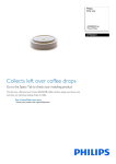
Figure 1.1 shows the main parts of the CP-9050 Automatic Liquid Sampler:
1.
2.
3.
4.
5.
6.
7.
8.
9.
CONTROL TERMINAL
CROSSRAIL
INJECTION HEAD
SYRINGE CARRIER
SYRINGE
INSTRUMENT BASE UNIT
TRAY
SOLVENT BOTTLE
WASTE BOTTLE
Figure 1.1 Main Parts CP-9050 Automatic Liquid Sampler.
CHROMPACK
1-3
CP-9050 AUTOMATIC LIQUID SAMPLER
1.2.1
INJECTION HEAD
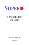
1. PLUNGER HOLDER
2. SYRINGE
3. SYRINGE FIXING LEVER
4. NEEDLE GUIDE
Figure 1.2 Syringe Carrier.
1.2.2
Introduction
See Figure 1.1 and 1.2 for details.
The Injection Head's function is to
transport liquids either from vial to vial
or from vial to the injection port of the
GC. The Injection Head carries the
syringe and provides the two essential
movements of the syringe:
Lowering the syringe to let the
needle pierce the septum of the vial
until the needle tip is well
submerged into the vial's liquid.
Moving the plunger up and down for
taking and dispelling liquids.
The syringe carrier holds the syringe,
the syringe itself is locked by the syringe
fixing lever while the head of the plunger
is fixed by "a screw" loaded plunger
holder.
The black needle guide - pushed down
by springs - holds the needle of the
syringe and centers the needle in the
septum cap of the injection port; it also
functions as sample vial detector.
The Injection Head is fastened to the
crossrail by two hex screws. These two
screws can be reached by mounting
holes in the back wall of the injection
head.
There is one electrical flat cable
connection between Injection Head and
Crossrail and one electrical flat cable
connection between Crossrail and
Instrument Base Unit.
CROSSRAIL
The Crossrail provides the movement of the injection Head from solvent and waste vial along
the sample tray to the injection port(s).
For the adjustment of the injection point the crossrail has to be moved towarts the injector(s) till
the Syringe Carrier can easily reach the used injection port(s).
This can easily be done by means of the alien hex screws which tighten the Crossrail on the
Instrument Base Unit.
1.2.3
INSTRUMENT BASE UNIT
The Instrument Base Unit houses the electronics, the control terminal and the tray compartment
which is partially open at the bottom.
At the left of the Instrument Base Unit vials for solvent(right) and waste (left) can be inserted.
The Instrument Base Unit is mounted with three screws on top of the sampler cover of the
CP-9001/2 GC.
1-4
CHROMPACK
Introduction
1.2.4
CP-9050 AUTOMATIC LIQUID SAMPLER
CONTROL TERMINAL
The Control Terminal is used during setup for programming the CONFIGURATION
PARAMETERS.
The normal programming of METHOD PARAMETERS is done via the CP-9001/2 keyboard and
display.
The Control Terminal contains a two line liquid crystal display (LCD) and a keyboard with eight
keys. On the first line of the display and sometimes at the beginning of the second line there is
a description of the menu or the parameter. Values are displayed on the second line below the
corresponding description. A selected parameter value - a value that can be changed - is
displayed as blinking.
On the keyboard, the key set ( M U C V ) selects the different functions (Methods, Utilities,
Clear and Validate).
The four arrow keys are used to input values. The parameter to be changed is selected by
pressing the '-•' or '«-' key until it is displayed as blinking. The value is increased with the ' t ' key
and decreased with the ' 1 ' key. If a low or high limit is reached, the value wraps around to the
other end of the valid range. If a value - having a valid range of 1 to 200 - is 10 and should be
set to 180, it is faster and more convenient to use the ' i ' key so the value wraps around to 200.
Holding the arrow key pushed down speeds up the changing of the value.
1.3
SOFTWARE
Five important software modifications have been implemented with the release of software
revision 2 (or higher) for the CP-9001/2:
a) One can control a CP-9050 sampler or a CP-9010 sampler or a 94X 'One Shot Sampler1. In
case of selecting the CP-9050 sampler in Page 1, Line 12 a new set of Pages 4 and 8 will
become visible. In case of selecting a 94X sampler Page 4 and 8 are as with software
revision 1.
NOTE:
A CP-9001/2 meant to control a CP-9050 sampler must be equipped with software
revision 2 (or higher). In case of 91X samplers, CP-9001/2 software revision 1 must be
used (which can control a combination of 94X and 91X samplers).
b) Baseline recording/subtraction is not possible anymore. Therefore Page 2 of the CP-9001/2
shows 'optional' for Line 3 and 4.
c)
NOTE:
Relevant Page 8 parameters (VIAL RANGES with coupled METHODS, PL.COUNT and
SEPTUM counters) plus some extra parameters of Page 7 (AUTOSTART and RESTART
TIME) will be saved in EEPROM at the sacrifice of GC method 12. As a consequence only
eleven GC methods can be programmed in Page 5.
Without sampler the five METHODS and the METHOD MODE in RUN CONTROL METHODS
will be saved as well.
d) One can control a temperature programmable on column injector (TP OCI) which can be
used with the CP-9050 liquid sampler.
The way the TP OCI is used can be selected in Page 1, Line 13 (one or two TP OCI's with
free programmable temperature or temperature coupled to the oven temperature).
In case of free programmable TP OCI's the relevant parameters show up in Page 7, Line 16
and up.
CHROMPACK
1-5
CP-9050 AUTOMATIC LIQUID SAMPLER
Introduction
e) Programming VLV 1 or VLV 2 in a Tx-program will only disable the default START or STOP
function of that relay. In software revision 1.0X both default START and STOP functions
were disabled in case VLV 1 and/or VLV 2 had been programmed in a Tx-program.
NOTE:
In case of a TP OCI relay VLV 2 is used for switching the fan cooling of the TP OCI, VLV 3
is used for the opening of the seal of the front TP OCI and VLV 4 is used for the opening
of the seal of the rear TP OCI.
1.4
GENERAL OPERATION
The CP-9001/2 with software release 2 (or higher) can store up to eleven GC methods.
NOTE:
A GC method holds all GC parameters of Page 1, 2, 3, 4, most of the parameters of Page
7 and some parameters of Page 10. Thus the sampler parameters of Page 4 are included
in a GC method!
When the CP-9050 sampler is activated (Page 1, Line 12. SAMPLER = 51) the CP-9001/2 gets
information from the sampler about the syringe size and tray (these values must be
programmed during setup of the sampler). The default values and data ranges for the sampler
parameters in the CP-9001/2 are set according to the syringe and tray installed.
Page 8 the RUN CONTROL SAMPLER Page of the CP-9001/2 links GC methods to vial ranges
of the sampler. Up to seven vial ranges can be defined while overlap between the vial ranges is
possible. If no method is specified with the vial range, all vials of this range will be processed
with the sampler parameters programmed in the active memory of the CP-9001/2.
The CP-9050 sampler itself can store up to nine sampler methods.
NOTE:
A sampler method holds only the sampler parameters of Page 4 of the CP-9001/2, which
are maintained even when the power to the CP-9050 sampler is switched off.
When the CP-9001/2 is started with the sampler active (Page 1, Line 12. SAMPLER = 51) all
sampler parameters to be used are downloaded to the sampler:
In case a GC method was specified with the vial range this GC method will be loaded in the
active memory of the CP-9001/2 and the sampler parameters from the active memory (the
parameters of Page 4 of the CP-9001/2) will be downloaded to the sampler.
If no GC method was specified with the vial range the sampler parameters from the active
memory (the parameters of Page 4 of the CP-9001/2) will be downloaded directly to the
sampler.
The sampler method number used for storage (1 - 9) depends on the value of SPECIAL
INJECTION METHODS ( only normal injection is possible!) in Page 4 of the CP-9001/2.
Default SPECIAL = 1 which means that all sampler parameters are stored in sampler
method 1 (used for normal injection).
NOTE:
-
1-6
A GC method is a method of the CP-9001/2 containing GC and sampler parameters.
GC methods are stored in the CP-9001/2.
A sampler method is a method of the CP-90S0 sampler containing only sampler
parameters. Sampler methods are stored in the sampler.
CHROMPACK
Installation
CP-9050 AUTOMATIC LIQUID SAMPLER
SECTION
INSTALLATION
2.1
2.2
2.3
2.4
2.5
2.6
2.7
2.8
2.9
2.9.1
2.9.2
2.9.3
2.9.4
2.9.5
2.9.6
2.10
2.10.1
2.10.2
2.10.3
2.10.4
2.10.5
2.10.6
2.10.7
2.10.8
2.10.9
2.10.10
2.10.11
2.10.12
2.10.13
2.10.14
2.10.15
2.10.16
2.10.17
2.10.18
2.10.19
2.10.20
2,11
Page
GENERAL
2-3
ASSEMBLING THE CP-9050 SAMPLER
2-3
CABLE CONNECTIONS CP-9050
2-4
SOFTWARE UPDATE OF THE CP-9001 GC
2-4
INSTALLING THE RS232 INTERFACE BOARD IN THE CP-9001/2 GC
2-5
MOUNTING/CONNECTING AN EXTRA RS232 PLUG AND CABLES IN THE CP-9001/2 GC 2-6
REPLACING THE STANDARD COVERS OF THE CP-9001 GC BY SAMPLER COVERS
2-6
REPLACING STANDARD SEPTUM CAP(S) BY SAMPLER SEPTUM CAP(S)
2-7
MOUNTING THE CP-9050 SAMPLER
2-7
SETTING THE CONFIGURATION PARAMETERS
2-8
ADJUSTING THE INJECTION DEPTHS FOR DIFFERENT INJECTION PORTS
2-8
INSTALLING A SYRINGE
2-9
CLEANING VIALS
2-9
ADJUSTING DEPTH FOR SAMPLE/SOLVENT PICKUP AND WASHING
2-10
CONFIGURATION SETUP AND ADJUSTMENT PROCEDURES
2-10
CONFIGURATION PARAMETERS
2-11
CONFIGURATION
2-12
NUMBER OF INJECTION PORTS
2-12
WASHING POSITION
2-12
START CYCLE SIGNAL
2-12
SYRINGE VOLUME
2-12
TRAY SELECTION
2-13
BCD ACTIVE STATE
2-13
START CYCLE BUZZER
2-13
MANUAL INJECTION BUZZER
2-13
BARCODE SCANNER
2-13
INJECTION POINTS POSITION
2-14
REFERENCE ADJUST
2-15
SAMPLE VIAL PENETRATION
2-16
CLEANING VIALS PENETRATION
2-16
MOTOR SPEED
2-17
PLUNGER TEST
2-18
SERIAL LINK BAUDRATE
2-19
SERIAL LINK TEST
2-19
POSITION SENSORS TEST
2-19
RESET TO DEFAULT
2-20
TABLES OF CONFIGURATION.METHOD AND UTILITY PARAMETERS
2-20
CHROMPACK
2-1
Installation
2.1
CP-9050 AUTOMATIC LIQUID SAMPLER
GENERAL
The installation comprises:
a) Assembling the CP-9050 sampler.
b) Software update of the CP-9001/2 GC.
c)
Installing the RS232 board in the CP-9001/2 GC.
d) Mounting/connecting an extra RS232 plug and cable in the CP-9001/2 GC.
e) Replacing the standard covers of the CP-9001 GC by the sampler covers.
f)
Replacing standard septum cap(s) by sampler septum cap(s).
g) Mounting the CP-9050 sampler.
h) System setup and adjustment procedures.
NOTE:
-
If CP-9001/2 and CP-9050 sampler were ordered together steps b) to g) can be
skipped, only the assembling of the sampler, the mounting of the sampler and the
system setup and adjustment procedures have to be done.
If the sampler was ordered separately, one or more of the nine steps have to be taken.
2.2
ASSEMBLING THE CP-9050 SAMPLER
After unpacking position the main body of the instrument on a flat table.
Unpack the Crossrail and the Injection Head.
Place the Crossrail on the LEFT and RIGHT Arm Support of the Instrument Base Unit and tight
it up with the 2 hexagonal screws.
Connect the flat cable of the Crossrail with the Instrument Base Unit.
Take the Injection Head and keep one of the screws on the long 2.5 mm Allen (hex) key and
line up the hole in the black syringe carrier plate with the upper hole in the back panel of the
injection head.
The two holes in turn need to be aligned with the upper hole in the cross-slide and the screw
has to be pushed through and tightened to mount the injection head while the guidance pins in
the cross-slide fit into the holes in the back panel of the injection head.
Now slide the syringe carrier downwards until the hole in the black syringe carrier plate lines up
with the lower hoie in the of the back panel of the injection head.
The second mounting screw can be inserted and tightened.
Connect the flat cable to the injection head.
CHROMPACK
2-3
CP-9050 AUTOMATIC LIQUID SAMPLER
Installation
2.3 CABLE CONNECTIONS
Check if the Instrument you received has the right voltage.
OPTIONS
SERIAL
BCD OUTPUT
GC IN/OUT
—1
0 1
(
Figure 2.1 Back panel CP-9050.
2.4
SOFTWARE UPDATE OF THE CP-9001 GC
A CP-9001 meant to control a CP-9050 sampler must be equipped with
software revision 2 (or higher).
The software revision number can be found in the upper line of page 10 of a CP-9001,
e.g.: REVISION: 2.01.
NOTE:
2-4
With software revision 1 only 94X and 91X type samplers can be controlled!
CHROMPACK
Installation
2.5
CP-9050 AUTOMATIC LIQUID SAMPLER
INSTALLING THE RS232 INTERFACE BOARD IN THE CP-9001/2 GC
A CP-9001/2 meant to control a CP-9050 sampler must be equipped with a revision 1.04 (or
higher) RS232 interface board.
The revision number of the RS232 interface board can be found at the printed circuit board.
This RS232 interface board has to be installed in one of the two slots at the basic control board
of the CP-9001/2.
Figure 2.2 shows the required dip switch/jumper setting and interface cable to the sampler
connector. If no TP OCI has been installed all positions of dipswitch S1 must be set to OFF. In
that case the TP OCI cannot be programmed: Page 1, Line 13 shows 'optional1.
If one TP OCI has been installed only position 1 must be set to ON and in case of two TP OCI's
position 2 must be set to ON. Page 1, Line 13 shows TP OCI, which means the TP OCI is
programmable.
no OCI
1xOCI
2xOCI
J1
Figure 2.2 RS232 Board; Switch/Jumper Settings and Cable Connection.
CHROMPACK
2-5
CP-9050 AUTOMATIC LIQUID SAMPLER
2.6
Installation
MOUNTING/CONNECTING AN EXTRA RS232 PLUG AND CABLES IN THE CP-9001/2 GC
DATAACQUISmON
For the RS232 communication with the
sampler a 25 pin female RS232
connector with cable has to be mounted
next to the 25 pin female connector for
the data-acquisition, see Figure 2.3.
SAMPLER
(s»\v.v.v.*.v.v.v;®| |s\v.v.v.v.v.'.v;®|
SATELLITES
Figure 2.3 Data Acquisition, Sampler and
Satellite Connections.
NOTE:
In case of an old CP-9001 two 3 mm
holes have to be drilled in the
mounting plate for the 25 pin
connector.
The cable from the connector must be
routed through the electronic
compartment of the CP-9001/2 to the
RS232 board and connected with the
5 pin plug at CM3, see Figure 2.2.
A cable with 25 pin male connectors at
both sides must be connected between
the 25 pin sampler connector at the
back of the CP-9001/2 and the 9 pin
connector at the back of the CP-9050
sampler marked ' Serial ). Use the 25/9
pins converter delivered with the
instrument.
In case one or two TP OCI's have been installed the cable with the/ro pin connector coming
from the CP-9001/2 must be connected to the t&'pin connector at the CP-9050 sampler marked
'GC IN/OUT '.
/, ?
W
2.7
REPLACING THE STANDARD COVERS OF THE CP-9001 GC BY SAMPLER COVERS
The left-hand cover over the flow controls (mounted with two screws), the middle cover over the
detector and injector area (mounted with two screws), the hinges for the middle cover (mounted
with two screws each) and the back cover over the electrical terminals (mounted with two
screws) have to be removed.
The back cover will be replaced by an aluminum back cover (mounted with two screws).
The left-hand, middle and old back cover will be replaced by one sampler cover over the
injector, detector, flow control and back cover area (mounted with two plastic hinges with four
M4 screws each).
NOTE:
2-6
In case of an old CP-9001 holes have to be drilled in the back side of the CP-9001, see
Figure 2.4. In that case the hinges must be mounted with M4 bolts and nuts.
CHROMPACK
Installation
CP-9050 AUTOMATIC LIQUID SAMPLER
203
234.8
u ^
625.2
IT
657
17
4.2
(4X)
Figure 2.4 Holes to be drilled in the CP 9001 for mounting the sampler cover.
2.8
REPLACING STANDARD SEPTUM CAP(S) BY SAMPLER SEPTUM CAP(S)
5mm
Figure 2.5 Septum Cap for Packed,
Splitter, Splitless Injectors.
2.9
The standard septum caps used for hand
injection and 91X/94X samplers need to be
replaced by special septum caps which
guide the black needle guide of the CP9050 sampler.
For packed, splitter and/or splitless injection
ports the one shown in Figure 2.5 will be
used.
The temperature programmed on column
injection port (TP OCI) with pneumatic head
has its own guidance part, see Figure 2.6
in Section 2.9.2 ADJUSTING THE
INJECTION DEPTHS.
MOUNTING THE CP-9050 SAMPLER
With the use of 3 screws (supplied) the CP-9050 sampler is mounted onto the GC top cover. 2
holes are located on the right side of the CP-9050 (one in front and one in the rear position).
The thirt hole is located in the bottom plate of the Instrument Base Unit (under the Sample
Tray).
The position of the sampler is hereby fixed.
Unpack the Sample Tray and place it into the Instrument Base Uniton.
Make sure that the Sample Tray is placed in the correct way which means the 2 pins in
the Instrument Base Unit fit into the bottom of the Sample Tray and the vial numbering
can be read.
The installation of the sampler can be divided in five steps:
a) SETTING THE CONFIGURATION PARAMETERS (Section 2.9.1).
b) ADJUSTING THE INJECTION DEPTHS (Section 2.9.2).
c) INSTALLING A SYRINGE (Section 2.9.3).
d) CLEANING VIALS (Section 2.9.4)
e) ADJUSTING DEPTH FOR SAMPLE/SOLVENT PICKUP AND SAMPLE/SOLVENT
WASHING (Section 2.9.5).
CHROMPACK
2-7
CP-9050 AUTOMATIC LIQUID SAMPLER
2.9.1
Installation
SETTING THE CONFIGURATION PARAMETERS
a) Connect the power cord.
b) Switch on the sampler while pressing the [M] key on the control terminal. The display shows
CONFIGURATION1 blinking.
c) Press the [V\ key to enter this option.
d) Follow the procedure given in Section 2.10.1 - 2.10.20 CONFIGURATION.
2.9.2
ADJUSTING THE INJECTION DEPTHS FOR DIFFERENT INJECTION PORTS
For packed, splitless and on column injection it is best to inject as deep as possible into the
injection port. For splitter injection (splitter injection port or splitter/splitless injection port in
splitter mode) it as advisable to inject less deep, especially in case the insert has been filled
with glass beads and/or glass wool. The syringes used do have a needle length of 51 mm.
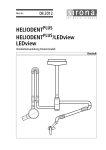
Figure 2.6 shows recommended injection depths for packed, splitless, splitter and on column
injection. For adjusting the injection depth follow the procedure given in Section 2.10.11
40mm
48mm
I
I
SPUTTER
SPUTLESS
46mm
TPOCI
(PACKED)
Figure 2.6 Injection depth for packed, splitter, splitless and on column injection
INJECTION POINTS POSITION.
When adjusting the injection depth it is handy to know the depth of the guidance part in the
septum cap used for packed, splitter or splitless injection port or in the guidance part of the
temperature programmable on column injector (TP OCI) which in both cases is 5 mm.
2-8
CHROMPACK
Installation
2.9.3
CP-9050 AUTOMATIC LIQUID SAMPLER
INSTALLING A SYRINGE
IMPORTANT:
1. PLUNGER HOLDER
For safety reasons it's advised to shut
off the power everytime a syringe have
to be adjusted.
2. SYRINGE
3. SYRINGE FIXING LEVER
4. NEEDLE GUIDE
Install the syringe in the syringe carrier.
Take care when inserting the syringe (with
one hand) that the needle is threaded into
the hole of the needle guide. Slide the rim
on top of the barrel a little bit in the slot
meant for it and while holding the upper
part of the plunger holder with your index
finger (of your other hand) push the srew
loaded plunger clamp up so that the
plunger head slips into the plunger holder.
Push the syringe in position and push the
plunger clamp down, then fix the screw
again. Finally the syringe can be locked by
turning the white syringe fixing lever 90°.
Move the plunger holder down as far as
possible to adjust dead volume to zero
(fixed by a hexagonal nut)
NOTE:
Figure 2.7 Syringe carrier with syringe
installed.
1) Standard Hamilton syringes can be
used.(700 -series 5 & 10 /#i)
2) The maximum plunger fill and inject
speed is for a 10 /#! syringe
maximum 25 jri/sec.
3) Proper working depends on the syringe state and the following points have to be
assumed:
- straight needle
- plunger freely slipping
- no plunger leakage
4) It's a good practice to execute some cleaning cycles (Utilities).
2.9.4
CLEANING VIALS
Use standard 10 ml vials.
Fill a vial with an appropriate solvent and put it into the right place of the vial holder.
Place an other "empty" vial on the left side for waste solvent.
Remark:
To prevent "plopping off" of the snapcap it's advised to change the snapcap with septum
on a regular basel
CHROMPACK
2-9
CP-9050 AUTOMATIC LIQUID SAMPLER
2.9.5
Installation
ADJUSTING DEPTH FOR SAMPLE/SOLVENT PICKUP AND WASHING
These adjustments are only required if one wants other settings than the default settings.
For these adjustments insert a vial in position 1 of the tray and insert solvent (right) and waste
(left) vials on the left hand side of the CP-9050. See Section 2.9.5 for adjusting solvent pickup
and wash penetration depth.
See Section 2.10.11 for adjusting the sample penetration depth.
NOTE:
The sample penetration depth depends on the vials used!
2.9.6
CONFIGURATION SETUP AND ADJUSTMENT PROCEDURES
The only way to change the configuration parameters is switching the power of the sampler on
while pressing the [M] key on the control terminal. The display shows 'CONFIGURATION'
blinking.
Press the "v" key to enter this option. The display shows 'NB of Inj. Points'.
With the ' t ' and ' i ' keys you can step through the possible values, with the '-»' and '•-' keys you
can step through the parameters.
Set all parameters to the values given in Section 2.10 CONFIGURATION PARAMETERS.
Press the ' C key to leave the CONFIGURATION PARAMETERS menu: 'CONFIGURATION'
starts blinking again.
By pressing the ' C key again the sampler returns to its
STANDBY mode showing:
FST LST INJ METH [M] [U]
1 1 1
1
[V]
NOTE:
-
Always press the ' V key to store the CONFIGURATION PARAMETERS! If the sampler
is switched off before the ' V key was pressed the entered parameters will not be
stored!
The sampler is now ready for operation, see Section 3 OPERATION.
2-10
CHROMPACK
Installation
2.10
NOTE:
CP-9050 AUTOMATIC LIQUID SAMPLER
CONFIGURATION PARAMETERS
Parameter
Possible values
Set value
INJECTION POINTS
WASH POSITION
START SIGNAL
SYRINGE VOLUME
TRAY SELECTION
BCD ACTIVE STATE
START CYCLE BUZZ
MANUAL INJ. BUZZ
BAR CODE SCANNING
INJECTION POSITION
REFERENCE ADJUST
SAMPLE PENETRATION
WASH PENETRATION
- SOLVENT
- WASTE
MOTOR SPEED(1 mm/sec)
-SYRINGE MOVE-UP
-SYRINGE WASH-DOWN
-SYRINGE SAMPL-DOWN
-SYRINGE INJECT
-SOLVENT PULL-UP(0.1//l/s)
-SOLVENT EJECT (0.1/zl/s)
-SAMPLE EJECT (0.1//I/S)
-SYRINGE TEST (0.1 //l/s)
-X & y axis SPEED (1mm/s)
SYRINGE TEST (0.1 fi\)
-FILLING
SERIAL BAUDRATE
SERIAL LINK TEST
POS SENSOR TEST
RESET TO DEFAULT
1/2/3/4
LEFT/RIGHT
GC READY/REMOTE
2/5/10//I
4x8/6x14/7x15/10x20
HIGH/LOW
ON/OFF
ON/OFF
ON/OFF
0,1,2,3
—
—
2
LEFT
REMOTE
5
7 x 15
HIGH
ON
ON
OFF
—
—
—
—
—
—
50 - 125
50 - 125
50 - 125
50 - 125
1 -250
1 -250
1 -250
1 -250
50 - 125
—
—
—
80
80
80
100
50
150
200
50
100
0-50
600/1200/2400/4800/9600
—
—
—
1
9600
—
—
1)
2)
1) The NO OF INJ POINTS must be set at 2 even if only one injection port is available!
2) Only important when non standard connections (options) are made (used).
CHROMPACK
2-11
CP-9050 AUTOMATIC LIQUID SAMPLER
2.10.1
Installation
CONFIGURATION
To enter the Configuration menu, turn power off then, while still pressing the [M] key, turn power on.
After the initialization cycle, the following message is displayed:
CONFIGURATION
[V] [C]
Press [V] to enter this option.
Select configuration parameter with [-*] or [«-]•
Press [V] to enter the selected parameter.
MODIFY the value of the selected parameter with [ t ] or [i]
Update and Quit with [V]
Discard and Quit with [C]
2.10.2
NUMBER OF INJECTION POINTS
Set the number of injection points.
NB OF INJ POINTS
(1-4)
2
[V] [C]
Set this value at 2, even if only one injection port is available.
2.10.3
WASHING POSITION
WASH POSITION
LEFT
[V] [C]
Set to LEFT with [ t ] or [4].
2.10.4
START SIGNAL
START
SIGNAL
REMOTE
[V]
Set to REMOTE with [ t ] or [*].
2.10.5
SYRINGE VOLUME
SYRINGE VOLUME
5
[V] [C]
S e t t o v o l u m e o f s y r i n g e u s e d w i t h [ t ]o r [ I ] .
2-12
CHROMPACK
Installation
2.10.6
CP-9050 AUTOMATIC LIQUID SAMPLER
TRAY SELECTION
SELECT ROW X COL
TRAY 7 X 15
[V] [C]
Set the 7 x 1 5 tray with [ t ] or [*].
2.10.7
BCD ACTIVE STATE
Sets the active logical level
BCD ACTIVE STATE
HIGH
[V] [C]
Select HIGH or LOW with [ t ] or [*].
Only important if this option is available and used.
2.10.8
START CYCLE BUZZER
START CYCLE BUZZ
ON
[V] [C]
Select ON or OFF with [ t ] or [ I ] .
2.10.9
MANUAL INJECTION BUZZER
MANUAL INJ BUZZZ
ON
Select ON or OFF with [ t ] or
2.10.10
[V] [C]
[i].
BARCODE SCANNING
BARCODE SCANNING
OFF
[V] [C]
This option is not available although on and off can be selected.
CHROMPACK
2-13
CP-9050 AUTOMATIC LIQUID SAMPLER
2.10.11
Installation
INJECTION POSITION
INJECT. POSITION
No.O
[V] [C]
Injection position 0 = rear injection port.
Injection position 1 = front injection port.
One or two injection points can be programmed depending on hardware present.
NOTE:
In case only one injection port is available the second injection point can be programmed
identical to the first one.
In this way programming front or rear does not matter: the injection is always done in the same
injection port.
Select the injection position to program (0 or 1) with [ t ] or [ i ] and press [V] to enter programming: the
following display appears:
"X" AXIS x 0.1 mm
No.O
0410
[V] [C]
'—- Position in 0.1 mm
1
— Injection Point being adjusted
Modify the axis position with [ t ] [I] keys in a step by step (brief action on the key) or continuous way
(key pressed).
Select the other axis (Y) with [<-] [->] and adjust in the same way.
"Y" AXIS x0.1 mm
No.O
0006
I
1
[V] [C]
— Position in 0.1 mm
Injection Point being adjusted
Finally select the PENETRATION with [<-] [->] and adjust in the same way.
"Z" AXIS
No.O
x0.1 mm
0030
1
[V] [C]
— Position in 0.1 mm
Injection Point being adjusted
2-14
CHROMPACK
Installation
CP-9050 AUTOMATIC LIQUID SAMPLER
For programming the penetration depth proceed as follows:
1) Move downwards with the [ t ] key until the bottom of the needle guide lies flat with the upper part of
the septum cap (for ease of adjustment place a piece of paper on top of the septum cap).
2) Note down the display value (typical value ± 800)
3) Calculate the display value required for a certain penetration depth by adding the depth of the guidance
part of the septum cap (5mm = 50 units) and the required injection depth (see section 2.9.2, figure 2.6)
to the in step 2) displayed value and store with [V].
Typical value for splitter (±1339) splitless (±1259) and TP OCI (±1306).
NOTE:
1) Before starting to grogram the positions of the injection points make sure the
Injection Head is in it's HOME position and also that you do not move the Injection
Head during the programming.
Otherwise you have to restart programming because the programmed value does not
match the actual value.
2) The best is to program all three values rougly and when the injection position is
neary reached then adjust exactly.
3) The [M] key allows to check the already stored X and Y positions of the running
injection point; the PENETRATION (Z) is reset to a safe value.
WARNING: always use [C] to leave a parameter when no adjustments where made.
\V\ always overwrite your stored values (in this case with the safe penetration value!).
4) In case of a TP OCI it's advised to do the programming without syringe to avoid
damaging the silicone seal inside the TP OCI.
2.10.12 REFERENCE ADJUST
REFERENCE ADJUST
[V] [C]
Press [V] to enter the programming.
"X" AXIS x 0.1 mm
REFERENCE
2944
[V] [C]
1
—• Position in 0.1 mm
To adjust the Reference position, align the right edge
of the Injection Head with the Right Arm Support of the
Instrument Base Unit (see fig.2.8 ) with [ t ] [i]
keys in a step by step (brief action on the key) or
continuous way (key pressed).
IMPORTANT:
1) This programming must be done
every time the arm position has
been modified (MECHANICAL !)
2) The Sample Tray and Cleaning Vials
Holder positions are RELATED to the
Reference adjustment.
For X REFERENCE
i
O M RIGHT «dq« of Uw Injection
H#od ond Uw RIGHT t d o * of th«
Arm Hofatar murt b t AUGNCO
Figure 2.8
CHROMPACK
2-15
CP-9050 AUTOMATIC LIQUID SAMPLER
2.10.13
Installation
SAMPLE VIAL PENETRATION
SMPL PENETRATION
M[C]
Allows to adjust the needle penetration in the sample vials.
Press [V] to enter the programming.
PENETR. x 0.1 mm
SAMPLE 1
0277
[V] [C]
t— Penetration Depth in 0.1 mm
1
— Detected vial
Since it is not possible to see how far the needle penetrate into the vial,proceed as follows:
1)
Measure the distance from septum to the desired penetration depth,
(use a spare capped vial).
Put a capped vial in position 1 of the tray.
Move the syringe downwarts with [ t ] key until the needle just touches the septum
of the vial.
Move the syringe further downwarts with the [ t ] key over the distance measured
in step 1).
2)
3)
4)
2.10.14
CLEANING VIALS PENETRATION
WASH PENETRATION
MIC]
7re penetration depth in solvent and waste vials can be individually adjusted.
Press [V] to enter the programming.
PENETR. x 0.1 mm
SOLVENT 0030
I
1
[V] [C]
— P e n e t r a t i o n D e p t h in 0 . 1 m m
S e l e c t t h e S O L V E N T o r W A S T E vial w i t h [ - J o r [ - ] a n d a d j u s t p e n e t r a t i o n w i t h [ t ] [i].
IMPORTANT:
Validate [V] ONLY when SOLVENT and WASTE penetration are programmed.
2-16
CHROMPACK
Installation
2.10.15
CP-9050 AUTOMATIC LIQUID SAMPLER
MOTOR SPEEDS
Motor speeds are in 1 mm/sec unless mentioned different.
The default values have proven good results and should be changed only if really necessary!
SYRINGE MOVE UP
80
[V] [C]
Syringe moving upwarts.
With [ t ] or [4] values can be changed.
SYRINGE WASH DOWN
80
[V] [C]
Syringe moving down to cleaning vials.
With [ t ] or [1] values can be changed.
SYRINGE SAMPL DOWN
80
[V] [C]
Syringe moving down to sample vial.
With [ t ] or [4] values can be changed.
SYRINGE INJECT
100
[V] [C]
Syringe moving down to inject sample.
With [ t ] or [4] values can be changed.
SOLVENT PULL UP
50
[V] [C]
Plunger pulling up solvent.
With [ t ] or [4] values can be changed.
SOLVENT EJECT
150
[V] [C]
Plunger ejecting solvent.
With [ t ] or [4] values can be changed.
CHROMPACK
2-17
CP-9050 AUTOMATIC LIQUID SAMPLER
SAMPLE EJECT
200
Installation
[V] [C]
Plunger ejecting sample during filling strokes.
With [ t ] or [i] values can be changed.
SYRINGE TEST
(0.1 //I/sec) 50
[V] [C]
With [ t ] or [ i ] values can be changed.
Plungerspeed when testing your syringe or checking your dead volume.
"X" & "Y" AXIS SPEED
(1 mm/sec)
100
[V] [C]
Speed with which the Injection Head moves to the injection port.
With [ t ] or [i] values can be changed.
2.10.16
SYRINGE TEST
SYRINGE TEST
This function allows to check if the syringe takes the programmed volume.
This is done with the plungerspeed mentioned above.
Press [V] to enter the programming.
The following display appears:
FILLING VOLUME
(0.1 /j\)
1
[V] [C]
Adjust the volume with [ t ] [I]
1)
2)
3)
4)
Press
Press
Press
Press
[V]: the plunger is moving up and down and then pulls up the programmed volume.
[V] again: the plunger goes to zero volume.
[V] same as step 1)
[C] Quit this parameter
At this point it may be necessary to align the zero volume position of the syringe (plunger is not going
down to zero).
This can easily be done by unscrewing the little hexagonal nut;press down the black plunger holder as far
as possible and re-tight the little hexagonal nut.
2-18
CHROMPACK
Installation
2.10.17
CP-9050 AUTOMATIC LIQUID SAMPLER
SERIAL BAUDRATE
SERIAL BAUDRATE
Press [V] to enter the programming.
The following display appears:
SERIAL BAUDRATE
BAUDS
9600
[V] [C]
Set the Baudrate to 9600 with [ t ] [4]
2.10.18
SERIAL LINK TEST
SERIAL LINK TEST
[V] [C]
This parameter can not be entered with [V].
With the Cp-9001/2 the communication from GC to SAMPLER can be checked by programming the
sampler mode (CP-9001/2: Page 1, Line 12) to 50 or 51.
The CP-9001/2 sends the following messages:
Sampler mode 50:
# 950000
Sampler mode 51:
#040000 #090000 #959991
The last part of these messages can be seen in the display of the CP-9050 sampler.
NOTE: See section 5.4.1 ADVANCED SERIAL LINK TEST for further testing.
2.10.19
POSITION SENSORS TEST
XL XR Y S PL SMP
1 O 1 0 0
0
The sensor state is displayed as:
1
= active
0
= inactive
XL
XR
Y
S
PL
SMP
IMPORTANT:
CHROMPACK
: INJECTION UNIT on LEFT side
: INJECTION UNIT on RIGHT side
: INJECTION UNIT back
. SYRINGE up
: PLUNGER pulled up
: VIAL detected
All the motors are powered off; Do not try to program any position after this test.
If necessary, turn power off and re-enter the configuration program.
2-19
CP-9050 AUTOMATIC LIQUID SAMPLER
Installation
EXAMPLE CHECKING THE "SAMPLE VIAL DETECTION SENSOR"
The CP-9050 sampler can detect whether a vial is inserted in the selected sample number
position. This is done by checking how deep the needle guide moves when the syringe carrier
moves down for sampling. If no vial is inserted the guide moves down to the sample tray and
the switch is not activated. The state of the switch is indicated at the display. The adjustment is
checked as follows:
1) Activate CONFIGURATION by pressing the [V] key while turning on the power.
2) Activate Parameter POS SENSORS TEST (value SMP=0)
3) Insert vial in position 2 of the sample tray.
4) Move injection head by hand to the first sample position.
5) Shift the needle guide down by hand slowly while observing the vial switch indication at the
display. It should be "O" at the beginning, turned to " 1 " when the needle guide is about 3 mm
below the top of the vial and switch back to "0" when the needle guide is about 3 mm above the
vial.
(the needle guide should "rest" on sample 2 while pressing downl).
2.10.20
RESET TO DEFAULT
With this function all changeable parameters are reset to default values. All user values are lost.
BE CAREFUL WHEN USING THIS FUNCTION! Its only use is to reset all parameters to save
values after making changes (e.g. sample penetration or injection depth too deep so the needle
may be damaged). Use this function if the CP-9050 sampler is reinstalled on another CP-9001/2
GC before setting up new values.
RESET TO DEFAULT
MIC]
Resets to default: METHODS, POSITIONS, MOTOR, SPEEDS.
Press [V], the following message is displayed:
ARE YOU SURE ??
<V> CONFIRM
[V] [C]
Press [V] to confirm or [C] to abort.
WARNING:
Be careful using this option because you will loose all your programmed parametersi.
2.11
TABLES OF CONFIGURATION.METHOD AND UTILITY PARAMETERS
In the next three tables - Table I, II and III - the default values are given for the
CONFIGURATION, METHOD and UTILITIES Parameters.
You can use these tables to note down your actual values.
2-20
CH ROM PACK
Installation
CONFIGURATION PARAMETERS
CP-9050 AUTOMATIC LIQUID SAMPLER
Table I
CONFIGURATION PARAMETERS
RANGE
DEFAULT
NB of Inj. Points
1 -4
2
Wash Position
Left/Right
Left
Start signal
GC_Ready/Remote
Remote
Syringe Volume
2/5/10
5
Tray Selection
7 x 1 5 / 6 x 14
7 x 15
BCD Active State
High/Low
High
Start Cycle Buzz
On/Off
On
Manual Inj. Buzz
On/Off
On
Bar Code Scanning
On/Off
Off
Injection Position
X-as (0.1 x mm)
Y-as (0.1 x mm)
Penetration (0.1 x mm)
7 - 4482
6 - 960
3 0 - 1339
7
6
30
Reference Adjust
X -as (0.1 x mm)
7 - 4482
1522
Sample Penetration
Penetration Depth
30 - 547
30
Wash Penetration
Solvent Penetration (0.1 x mm)
Waste Penetration (0.1 x mm)
30 - 547
30 - 547
30
30
* Syringe MOVE-UP
* " WASH-DOWN
* " SAMPL-DOWN
* " INJECT
* Solvent PULL-UP (01.//I/sec.)
* " EJECT
* Sample EJECT
* Syringe TEST (0.1 //I/sec)
* X & Y axis SPEED (1 mm/sec)
50 - 125
50 - 125
50 - 125
50 - 125
1 -250
1 -250
1 -250
1 -250
50 - 125
80
80
80
100
50
150
200
50
100
Syringe test
Filling (0.1 ^ )
0 - 100
1
PROGRAM
Motor Speed ( x 1 mm/sec )
Serial Baudrate ( x 100 )
6/12/24/48/96
96
Serial Link Test
-
-
Pos Sensors Test
-
-
RESET TO DEFAULT
-
-
CHROMPACK
2-21
CP-9050 AUTOMATIC LIQUID SAMPLER
Installation
METHOD PARAMETERS
Table II
METHOD PARAMETERS
RANGE
DEFAULT
-
Injection MODE (SPECIAL)
0
0
Volume SAMPLE (//I)
Volume AIR
(//I)
0.1 - 5.0
0 - 5.0
0.5
1
Clean Syringe SOLVENT (PRE)
Clean Syringe SAMPLE (PRE)
0
0
0
0
Filling Vol. (//I)
Number Fillstrokes
0.1 - 5.0
0 - 99
2.5
7
Viscosity
0
0.5
-
5.0
5.0
0
0
- 99
- 99
-
9.9
Plunger speed FILL (fills)
Plunger speed INJ. (//l/s)
0.1 - 25
0.1 - 25
5
25
Select Inj. Port
Rear / Front
Rear
0
0
- 99
- 99
0
0
Inj. Delay PRE (sec)
Inj. Delay POST (sec)
0
0
- 99.9
- 99.9
0.3
0.3
Clean Syringe SOLVENT
(POST)
0
- 99
0
Splitter PRE
Splitter POST
(sec)
(sec)
UTILITY PARAMETERS
Table
UTILITY PARAMETERS
Inject.
Single
Samp.
1
Washing
Syringe
Cycles
1
Inject
Manual
Pre
0
Select
Tray
Start Cycle Delay
x 1 min
2-22
METH.2
0
Volume SOLVENT (//I)
Volume AIR
ip\)
(Sec)
METH.1
Display
Meth.
1
V
c
V
c
V
c
Row x Col
7
x 15
V
c
0
V
c
Pst
0
CHROMPACK
Operation
CP-9050 AUTOMATIC LIQUID SAMPLER
SECTION 3
OPERATION
3.1
3.2
3.3
3.4
3.5
3.6
3.7
3.8
3.9
3.10
3.11
INJECTION TECHNIQUES
SYRINGES
PREPARING VIALS
ACTIVATING THE SAMPLER PROGRAM
PROGRAMMING STANDARD SAMPLER PARAMETERS
PROGRAMMING SPECIAL SAMPLER PARAMETERS
PROGRAMMING THE RUN CONTROL SAMPLER PARAMETERS
STATUS INFORMATION (PAGE 8 AND STATUS PAGE)
TEMPERATURE PROGRAMMABLE ON COLUMN INJECTOR
OPERATING HINTS
SUMMARY OF PROGRAMMING
CHROMPACK
Page
3-3
3-5
3-5
3-6
3-7
3-9
3-12
3-14
3-16
3-17
3-20
3-1
0 Deration
3.1
CP-9050 AUTOMATIC LIQUID SAMPLER
INJECTION TECHNIQUES
With the CP-9050 sampler 'plunger in barrel' syringes are used, which means the needle
volume of the syringe used has to be taken in account: what stays in the syringe after injection
depends upon injection technique used, sample, GC parameters and sampler parameters.
With the CP-9050 sampler different injection techniques can be used: 'normal', hot needle',
sandwich1. Since many parameters are programmable - not only pre injection solvent and/or
sample cleaning, post injection solvent cleaning etc., but also speed of injection and residence
time before and after injection - all kinds of injection techniques can be optimized.
To show the possibilities of these samplers three examples of injection techniques will be
discussed:
a) A 'HOT NEEDLE INJECTION.
b) A SIMPLE 'SANDWICH' INJECTION.
c) A MORE ELABORATE 'SANDWICH' INJECTION.
In these examples we assume:
the needle volume is 1 /J\.
0.2 jt/l of sample or solvent evaporates from the needle during injection.
a) A 'HOT NEEDLE' INJECTION.
After sampling 1 /J\ (1) the total amount
of sample in barrel + needle is 2 fi\
as can be seen after taking a 1 fj\ air
plug (2). By programming a pre injection
delay of a few hundred milliseconds the
needle can be heated before injection.
During injection part of the sample in the
needle evaporates, thus after injection
(3) stays 0.8 /il. In this way we have
injected 2 - 0.8 = 1.2 A/I of sample
(assuming no discrimination during the
evaporation from the needle!).
Figure 3.1 'Hot needle1 injection.
CHROMPACK
3-3
CP-9050 AUTOMATIC LIQUID SAMPLER
Operation
A SIMPLE 'SANDWICH' INJECTION.
b)
Figure 3.2 A simple 'sandwich' injection.
A possibility to inject the sampled
amount more precisely will be when we
start sampling with a needle filled with
solvent (using pre injection solvent clean
flushes) see (1). Sampling must then be
done with no fill strokes programmed,
just filling the barrel once to the fj\ mark
(2). The syringe contains now 1 //I
solvent + 1 (j\ sample (3). During
injection the total amount of sample will
be transferred to the injection port while
part of the solvent evaporates from the
needle (4). After injection stays 0.8 //I.
So we have injected 1 //I sample + 0.2 fj\
solvent (assuming no mixing of solvent
and sample).
A MORE ELABORATE 'SANDWICH' INJECTION.
c)
A further improvement can be made if
we separate the sample and the solvent
by an air plug. Also more solvent can be
used as is illustrated here.
After pre injection solvent clean flushes
a solvent plug of 0.5 fj\ is taken (1)
whereafter an air volume of 0.2 fji (2).
Then 1 //I of sample is taken (3) + an
extra air volume of 0.8 /J\ (A). During
injection the total amount of sample will
be transferred to the injection port
+ 0.7 //I (0.5 + 0.2 j/l) of solvent. What
remains in the needle is 0.8 fj\ of
solvent.
Figure 3.3 A more elaborate 'sandwich' injection.
3-4
CHROMPACK
Operation
3.2
CP-9050 AUTOMATIC LIQUID SAMPLER
SYRINGES
The CP-9050 sampler uses standard Hamilton 700 series syringes (5 or 10 fji) with a needle
length of 51 mm, an OD of the needle of 0.47 mm (gauge 26S) and point style 1 which means
the needle has a bevel of 17° and is slightly bent inward. Therefore, protecting it from
blockages.
Special syringes with slightly thicker (0.52 mm = gauge 25S) needles can be used as well for
packed, splitter and splitless injectors (all with septum cap).
For the on column injector the needle must have an OD of 0.47 mm to make it possible to get
into a 0.53 mm column or retention gap.
Note:
The maximum plunger fill and inject speed for a S and 10 ui syringe is 25 pi/sec.
3.3
PREPARING VIALS
Selecting sample/solvent/waste vials
Standard 2 ml vials, 2 ml vials with 0.1 ml inserts or 0.1 ml conical vials can be used in the 7 x
15 tray.
Dimensions: OD ^ 1 1 . 6 mm, height 30 - 38 mm.
For the solvent and waste vials 10 ml vials are used.
Dimensions: OD = 22.5 mm, height = 48 mm.
Filling sample vials
For obtaining reliable, high performance results with the sampler and preventing contamination
or injection volume problems do fill the vials half full or a little bit more.
If the vials are almost empty the contribution from previous sample injection or solvent washes
may affect the sample (cross contamination, dilution effect).
If the vials are almost full a vacuum may interfere with the syringe measuring a precise volume.
Capping sample vials
Use a crimper to put on the airtight crimp caps.
Be sure the cap is airtight; if you can turn the cap by hand easily the cap is too loose and
sample evaporation may occur.
Be sure the cap is centered otherwise the syringe needle could hit the cap.
Be sure the cap is not tightened too much. If so the septum is not flat anymore and the
syringe tends to core a curved vial septum and drop small pieces of the material into the
sample.
Solvent and waste vials
To fill the solvent vial or empty the waste vial it is required to move the injection head by hand
to a place where it does not interfere with pulling the vial out of the vial holder. Before the next
injection cycle the position of the injection head will be automatically reset to the waste position.
NOTE:
The septum on the solvent and waste vials is part of an effective syringe needle cleaning
concept. Not using a septum or not replacing these septa on a regular basis may cause
sample cross contamination or even "plopping off",of the snapcap.
CHROMPACK
3-5
CP-9050 AUTOMATIC LIQUID SAMPLER
3.4
Operation
ACTIVATING THE SAMPLER PROGRAM
Page 1:
1 .COL.LIMIT
2 .DET.TEMP
3 .INJ.TEMP
4 .OVEN INIT
actual
101.
0.
0.
0.
21.
0.
0.
99.
0.
1.
1.
5 •OVEN FINAL
6 .OVEN RISE
7 .TIME INIT
8 TIME FINAL
9 .STAB.TIME
10 .CYCLES
11 .TX-MODE
off
12 .SAMPLER 90IX on
13 .TP OCI
0.
51=901X on,ll=94X on
SAMPLER
51
In Line 12 one can choose the sampler type and mode. The following codes are possible:
50
NOTE:
The CP-9010 or CP-9050 sampler page (Page 4) is programmable, the sampler is off,
pressing START starts a GC cycle without starting the CP-9010 or
CP-9050
sampler, Page 8: RUN CONTROL ME r HODS can be active.
51
The CP-9010 or CP-9050 sampler pages (Page 4 & 8) are programmable, the sampler
is on, pressing START starts a GC cycle while starting the CP-9010 or CP-9050
sampler, Page 8: RUN CONTROL SAMPLER will be active.
10
The 94X sampler page (Page 4) is programmable, the sampler is off, pressing START
starts a GC cycle without starting the 94X sampler, Page 8: RUN CONTROL METHODS
can be active.
11
The 94X sampler page (Page 4) is programmable, the sampler is on, pressing START
starts a GC cycle with starting the 94X sampler, Page 8: RUN CONTROL METHODS
can be active.
- Before programming the CP-9050 sampler page (Page 4) one has to activate the
sampler at least once (after power up of the CP-9001/2) by entering 51 for SAMPLER.
By doing this the CP-9001/2 gets information from the CP-9050 sampler about
installed/programmed syringe size and vial tray. The default values and programmable
data ranges will be set according to the installed/programmed syringe size and vial
tray (See Section 2.10 CONFIGURATION PARAMETERS about programming the
syringe size and vial tray).
In case the CP-9050 sampler has been activated the keyboard of the CP-9050 sampler
will be locked; the function keys [M],[V],[U] and [C] disappear in the display.
FST, LST, INJ and METH stay visible on the display of the sampler.
The only key that stays active (only during sampling) will be the [C] key. With the [C]
key it is possible to abort the started cycle in the sampling phase of the CP-9050
sampler: sampler and GC will be stopped. Pressing the red START/RESET button on
top of the CP-9001/2 or pressing the STOP/RESET key at the CP-9001/2 keyboard
twice has the same effect but these keys will be active all the time, not only in the
sampling phase of the CP-9050 sampler.
In case of TP OCI('s) the dipswitches at position 1 or 2 must be set. Then Line 13
shows ~? OCI. Otherwise (all dipswitches OFF) Line 13 shows 'optional'.
Operation
3.5
CP-9050 AUTOMATIC LIQUID SAMPLER
PROGRAMMING STANDARD SAMPLER PARAMETERS
If the sampler/sampler mode has been set to 50 or 51 the first part of Page 4 looks like:
90IX SAMPLER
1.INJ.VOL.
2.INJ./VIAL
3.<CLEAN SMP
4.FILLSTR.
5.>CLEAN SLV
6.INJ.PORT
7.OPTIONS
.1 - 5. 0
INJ.VOL.
NOTE:
-
0.5
1.
0.
7.
0.
rear
0.
0.5
Values and data ranges shown here assume a 5 /ii syringe installed (programmed
during setup, see Section 2.10 CONFIGURATION PARAMETERS about programming
the syringe size). Default values for the parameters and data ranges depend on the
syringe size programmed.
Once activating the CP-9050 sampler (by setting Line 12 in Page 1 to-51) shows
values and ranges for the syringe size programmed in the CP-9050 liquid sampler.
The first part of Page 4 contains parameters for daily use. The second part of Page 4,
accessible by putting a ' 1 ' in Line 7 OPTIONS, contains parameters that will be changed less
frequently.
Explanation of the parameters (data ranges and defaults given for 5 //I syringes.
LINE 1. INJ. VOL.
INJECTION VOLUME in //I (0-5 //I in steps of 0.1 //I; default 0.5 /J\)
This parameter specifies the volume to be sampled and injected.
Since 'plunger in barrel1 syringes are used, needle volume has to be taken in account!
NOTE:
By filling the needle with solvent (PRE INJECTION SOLVENT CLEAN FLUSHES > 0) one
can compensate for needle dead volume. In that case PRE INJECTION SAMPLE CLEAN
FLUSHES and FILL STROKES must be set to zerol
LINE 2.INJ./VIAL
NUMBER OF INJECTIONS PER VIAL (1-99; default 1)
This parameter specifies the number of times each sample will be injected.
CHROMPACK
3-7
CP-9050 AUTOMATIC LIQUID SAMPLER
Operation
LINE 3.<CLEAN SMP
NUMBER OF PRE INJECTION SAMPLE CLEAN FLUSHES (0-99; default 0)
This parameter specifies the number of times the syringa is washed with sample.
This option is used when the solvent used in a post injection clean cycle is not compatible with
the analysis or when no pre injection solvent clean cycle is used.
NOTE:
If you want a solvent plug on top of the sample to compensate for needle dead volume
(PRE INJECTION SOLVENT CLEAN FLUSHES > 0) this parameter must be set to zero.
LINE 4.FILLSTR.
NUMBER OF FILL STROKES (0-99; default 7)
This parameter specifies the number of pull ups using the FILL VOLUME. This parameter
serves to control the filling of the syringe. It may happen that air bubbles remain below the
plunger after a pull up. By moving the plunger down fast after a pull up these air bubbles can be
worked out.
NOTE:
If zero is selected for FILL STROKES the plunger will be pulled up only once using the
INJECTION VOLUME!
If you want a solvent plug - with the volume of the syringe needle - on top of the sample to
compensate for needle dead volume {PRE INJECTION SOLVENT CLEAN FLUSHES > 0) this
parameter must be set to zero.
LINE 5.>CLEAN SLV
NUMBER OF POST INJECTION SOLVENT CLEAN FLUSHES (0-99; default 0)
This parameter specifies the number of times the syringe is washed with solvent after the
injection.
NOTE:
If the sampler is stopped in the sampling phase (before injection but after taking some
sample) the syringe is cleaned with the programmed number of SOLVENT CLEAN
FLUSHES.
LINE 6.INJ.PORT
INJECTION PORT (front/rear; default rear)
Here one can select the injection port to be used in case a front and a rear injection port are
available.
LINE 7.OPTIONS
Message 'ENTER 1 to program' (0-1; default 0)
By entering a ' 1 ' in this line a new page with additional parameters shows up. This page
contains parameters that need to be changed less frequently. For further details see Section 3.6
PROGRAMMING SPECIAL SAMPLER PARAMETERS.
NOTE:
3-8
Entering a ' 1 ' is the only way to get access to the additional parametersi
C'U<OMPACK
0 Deration
3.6
CP-9050 AUTOMATIC LIQUID SAMPLER
PROGRAMMING SPECIAL SAMPLER PARAMETERS
By entering a ' 1 ' in LINE 7.OPTIONS a new page with additional parameters shows up:
SAMPLER OPTIONS
1 .AIR VOL.
2 .FILL VOL.
3 .<CLEAN SLV
4 .SOLV.PLUG
5 .AIR PLUG
6 .VISCOSITY
7 .FILL SPEED
8 .INJ.SPEED
9 .<INJ.DELAY
10 .>INJ.DELAY
11 .<INJ.TIME
12 .>INJ.TIME
13 .SPECIAL
1.
2. 5
0.
0.
0.
0. 5
5.
25.
0. 3
0. 3
0.
0.
1
0 - 5.0 111
1.
AIR VOL.
LINE LAIR VOL.
AIR VOLUME (0-5 //I in steps of 0.1 //I; default 1 /J\)
The air plug pulled up after taking the sample - after all programmed fill strokes - can reduce
evaporation from the needle. The air plug can also be used for the 'hot needle' injection
technique.
NOTE:
Do not program a total volume (= INJ.VOL. + AIR VOL. + SOLV. PLUG + AIR PLUG) which
is bigger than the total syringe volume!
LINE 2.FILL VOL.
FILL VOLUME (0-5 fi\ in steps of 0.1 /ii; default 2.5 /j\)
This parameter specifies the - minimum - volume used for the FILL STROKES. If the
programmed INJECTION VOLUME is higher than the FILL VOLUME the INJECTION VOLUME
will be used for all FILL STROKES.
NOTE:
The FILL VOLUME is used for FILL STROKES and PRE INJECTION SAMPLE CLEAN
FLUSHES, the total syringe volume is used for PRE and POST INJECTION SOLVENT
CLEAN FLUSHES.
LINE 3.<CLEAN SLV
NUMBER OF PRE INJECTION SOLVENT CLEAN FLUSHES (0-99; default 0)
This parameter specifies the number of times the syringe is washed with solvent before
sampling (PRE INJECTION SAMPLE CLEAN FLUSHES and/or FILL STROKES).
NOTE:
By filling the needle with solvent before sampling one can compensate for needle dead
volume (PRE INJECTION SOLVENT CLEAN FLUSHES > 0). In that case PRE INJECTION
SAMPLE CLEAN FLUSHES and FILL STROKES must be set to zerol
CHROMPACK
3-9
CP-9050 AUTOMATIC LIQUID SAMPLER
Operation
LINE 4.SOLV.PLUG
SOLVENT PLUG (0-5 A/I in steps of 0.1 fil; default 0 A/I)
SOLVENT PLUG and AIR PLUG will be used in the so-called sandwich injection technique,
where solvent and sample will be separated by an air plug. With PRE INJECTION SOLVENT
CLEAN FLUSHES one can get a solvent plug with the volume of the needle, while here the
SOLVENT PLUG can be programmed (solvent volume = programmed value plus the needle
volume).
NOTE:
-
When using a SOLVENT PLUG the conditions PRE INJECTION SAMPLE CLEAN
FLUSHES = 0 and FILL STROKES = 0 must be fulfilled!
If it is not possible to enter a value for this parameter (DATA RANGE blinking) check
the above mentioned conditions.
Do not program a total volume (= INJ.VOL. + AIR VOL. + SOLV. PLUG + AIR PLUG)
which is bigger than the total syringe voiumel
-
LINE 5.AIR PLUG
AIR PLUG (0-5 A/I in steps of 0.1 A/I; default 0 A/I)
AIR PLUG and SOLVENT PLUG will be used in the so-called sandwich injection technique,
where solvent and sample will be separated by the programmed AIR PLUG.
NOTE:
-
-
When using a SOLVENT PLUG and AIR PLUG the conditions PRE INJECTION
SAMPLE CLEAN FLUSHES = 0 and FILL STROKES = 0 must be fulfil led I
if it is not possible to enter a value for this parameter (DATA RANGE blinking) check
the above mentioned conditions.
Do not program a total voiume (= INJ.VOL. + AIR VOL. + SOLV. PLUG + AIR PLUG)
which is bigger than the total syringe volume!
LINE 6.VISCOSITY
VISCOSITY DELAY (0-9.9 s in steps of 0.1 s; default 0.5 s)
T
parameter specifies the delay between sample pullup and sample ejection while sampling
wnn FILL STROKES. The same delay time is used after the last fill stroke before the syringe wiil
be taken out of the vial. This feature is especially useful for handling viscous samples.
LINE 7.FILL SPEED
PLUNGER SPEED while pulling up sample (0.1-25 fills in steps of 0.1 fills] default 5 jt/l/s)
The speed of the upward plunger movement during sampling (PRE INJECTION SAMPLE
CLEAN FLUSHES and FILL STROKES) can be set here. This feature is especially useful for
handling viscous samples.
LINE 8.INJ.SPEED
PLUNGER SPEED while injecting (0.1-25 fills in steps of 0.1 A/I/S; default 25 fills)
The speed of the downward plunger movement during injection can be set here.
So if a fast or slow injection has to be performed the plunger speed can be set here accordingly.
3-10
CHROMPACK
Operation
NOTE:
NOTE:
CP-9050 AUTOMATIC LIQUID SAMPLER
LINE 9.<INJ.DELAY
PRE INJECTION DELAY (0-99.9 s in steps of 0.1 s; default 0.3 s)
After the syringe moves down into the injection port a certain delay time can be programmed
before the sample will be injected.
In case of a fast injection one can select a short delay time and in case of the so-called hot
needle injection technique this delay time must be set long enough to warm up the needle.
In case of temperature programmable on column injection ports (TP OCI's) this time sets
the time the pneumatic seal is closed before injection, see Section 3.9 TEMPERATURE
PROGRAMMABLE ON COLUMN INJECTOR.
LINE 10.XNJ.DELAY
POST INJECTION DELAY (0-99.9 s in steps of 0.1 s; default 0.3 s)
This parameter specifies the delay between injection and the moment the syringe will be pulled
out of the injection port. This delay time can be useful for controlling the evaporation from the
needle.
In case of temperature programmable on column injection ports (TP OCI's) this time sets
the time after the injection when the syringe will be withdrawn.
LINE 11.<INJ.T1ME
PRE INJECTION TIME for valve switching (0-999 s in steps of 1 s; default 0 s)
This parameter specifies the time between start of the sampler cycle and injection. In practice to be effective - the programmed time should be longer than the time between start of sampler
cycle and injection (this time depends on the number of fill strokes and the number of pre
injection sample/solvent clean flushes).
LINE 12.>INJ.TIME
POST INJECTION TIME for valve switching (0-999 s in steps of 1 s; default 0 s)
This parameter specifies the time between injection and deactivation of a valve.
REMARK
Line 11 and 12 are not being used; Because the CP-9050 is a fully integrated Liquid
Sampler, programming of a valve is done by using the TX table of the CP-9001/2!.
Example:
- One wants to activate a splitter/splitless valve connected to relay-3 (VLV 3) of the CP-9001/2
before injection.
- This valve must stay activated till 2 minutes after injection.
The following parameters must be programmed:
TX-program (page 3):
1 Time
0
Valve/Ext
3
2.Time
2
Valve/Ext
-3
Note:
CHROMPACK
- If the TX-program of the CP-9001/2 relay 3 (VLV 3) is programmed at time zero it
will be activated when the sampler cycle starts, so before the GC program!
- The time between start of the sampler and start of the GC program is dependent
on the activities of the sampler (number of clean strokes.fill strokes etc.).
- Two minutes after injection relay 3 will be deactivated.
3-11
CP-9050 AUTOMATIC LIQUID SAMPLER
Operation
LINE 13.SPECIAL
Choice of sampler method. The default value is 1 which means all sampler parameters will be
loaded from the CP-9001/2 to method 1 of the sampler.
3.7
PROGRAMMING THE RUN CONTROL SAMPLER PARAMETERS
If the sampler/sampler mode has been set to 51 the first part of Page 8 looks like:
RUNr CONTROL SAMPLER
FRST
LAST
1.
1. 105.
2.
0.
0.
3.
0.
0.
4.
0.
0.
5
0.
0.
6
0.
0.
7
0.
0.
8 PRIORITY
9 .PL.COUNT
10 .RESET
METH
0.
0.
0.
0.
0.
0.
0.
0.
0.
0
SELECT LINE
LINE 1 - 7.FRST LAST METH
In these 7 lines vial ranges (1 -105) can be coupled with GC methods (1 -11). Up to seven vial
ranges can be defined while overlap between the vial ranges is possible.
While entering values for FIRST and LAST vial a check is done for LAST vial ^ FIRST vial.
Deactivating a vial range can be done by programming zero for FIRST and LAST vial.
If FIRST vial = 0 while LAST vial > 0 a message UNDEFINED VIAL RANGE appears when the
CP-9001/2 is started.
If all vial ranges (FIRST and LAST) are set to zero the sampler/GC cannot be started.
If no method is specified with the vial range, all vials of this range will be processed with the
sampler parameters programmed in the active memory of the CP-9001/2.
If a sampler/GC run is stopped - by pressing the STOP/RESET key at the keyboard twice or
pressing the START/RESET button on top of the CP-9001/2 once - the sampler continues with
the next programmed injection when the CP-9001/2 is restarted by pressing the START key at
the keyboard or the START/RESET button on top of the GC (if the sampler run is stopped
before injection the same injection is done at restart!).
If a programmed vial range is processed a '*' in front of the line number of that vial range will
mark that condition. When resetting the CP-9001/2 (LINE 10. RESET = 0) these '*' marks
disappear.
If all programmed injections were done - so ail programmed vial ranges will be completed and
have a '*' in front of all vial ranges - restarting the CP-9001/2 (by pressing the START key or
the START/RESET button) starts the sampler all over again with the first injection of the first vi~
of the first programmed vial range.
3-12
CHROMPACK
Operation
NOTE:
CP-9050 AUTOMATIC LIQUID SAMPLER
-
In case a sampler/GC run is stopped after one or more injections were done and one
wants to start all over again the CP-9001/2 must be reset (LINE 10. RESET = 0)
otherwise the sampler continues with the next injectionl
In case a vial range is changed (or just pressing three times ENTER after selecting a
vial range by selecting LINE X) the CP-9001/2 will be reset in the same way as with
LINE 1O.RESET= 0.
The programmed values for VIAL RANGES and coupled METHODS are stored in
EEPROM. Switching the CP-9001/2 off and on again makes the last programmed
values active again.
-
LINE 8.PRIORITY
PRIORITY SAMPLE
During a sampler/GC run a priority sample can be programmed. Enter the vial number for the
priority sample followed by a decimal point and the method number to be used with that priority
sample.
Example:
Vial position 91 wiil be used for a priority sample. This sample must be analyzed using GC
method-2. Program Line 8 with 91.02 (note the zero in front of the method number!).
When the running GC cycle comes to an end the priority sample will be analyzed according the
parameters of GC method 2. When the priority sample has been analyzed, the sampler/GC
continues where it stopped.
LINE 9.PL.COUNT
PLUNGER COUNT WARNING LIMIT
Dependent on the conditions used the syringe need to be cleaned or replaced after some time.
In many cases the number of plunger strokes executed is an important factor. The number of
plunger strokes is counted by the sampler itself while a warning limit (< 9800) can be
programmed here. The value entered will be multiplied by 100: for a warning limit of 9800 one
has to enter 98.
NOTE:
In case values < 100 need to be programmed, enter the value after a decimal point: for a
warning limit of 50 enter '.50' or '.5' (for 9 enter '.09'!).
LINE 10.RESET
RESET FUNCTION
0 Resets the sampler cycles which means when the CP-9001/2
- with sampler activated - is started again the sampler starts with the first injection of the first
vial in the first vial range programmed.
NOTE:
It is wise to use RESET = 0 before starting a new series of injections to be sure the
sampler starts with the first injection of the first vial in the first vial range programmed. In
many cases the history of the sampler/GC combination is not known exactlyl
1
NOTE:
Resets the front injection septum counter to zero. After changing the septum of the front
injection port the septum counter must be reset.
In case of a temperature programmed on column injection port (TP OCI) this counter can
be used to see if cleaning of the TP OCI is needed or if the seal must be replaced.
CHROMPACK
3-13
CP-9050 AUTOMATIC LIQUID SAMPLER
2
NOTE:
Operation
Resets the rear injection septum counter to zero. After changing the septum of the rear
injection port the septum counter must be reset.
In case of a TP OCI this counter can be used to see if cleaning of the TP OCI is needed
or if the seal must be replaced.
3
Resets the plunger stroke counter to zero. After cleaning/replacing a syringe the plunger
stroke counter must be reset.
NOTE:
RESET only works in non run model
This might also be a good time to change the "Snap cap with septum" on the Waste and
Solvent viall
3.8
STATUS INFORMATION (PAGE 8 AND STATUS PAGE)
The second part of Page 8 shows up after pressing '*':
RUN CONTROL SAMPLER
SEPTUM
front
0.
rear
0.
SET PL.COUNT
ACT.PL.COUNT
0.
0.
VIAL
0.
:
INJ./VIAL :
ACT. INJ. :
ACTIVE METHOD
0.
0.
0.
This Page contains 'status' information. Most information is updated after an injection.
SEPTUM
INJECTION COUNTER as a reminder for exchanging a septum. Septum counters for front and
rear injection port are given. After every injection the septum counter of the injection port used
is increased by one. After changing the septum of that injection port the septum counter must
be reset to zero.
3-14
CHROMPACK
Operation
CP-9050 AUTOMATIC LIQUID SAMPLER
SET PL.COUNT
PROGRAMMED PLUNGER COUNT WARNING LIMIT
The programmed value is displayed.
ACT.PL.COUNT
ACTUAL PLUNGER COUNT
The number of plunger counts (after the last RESET = 3) is displayed.
VIAL
ACTIVE VIAL
The active vial is displayed.
INJ.A/IAL
PROGRAMMED INJECTIONS PER VIAL
The programmed number of injections per vial is displayed.
ACT. INJ.
ACTUAL INJECTION
The actual injection from the active vial is displayed.
ACTIVE METHOD.
The active method used is displayed.
The STATUS page of the CP-9001/2 gives for the sampler information about the total number of
injections to be made, the actual injection, the active vial and the active GC method:
**STATUS**
10 :05
READY
RUN TIME
0.
CYCLES 1 : 20
actual
set
OVEN
50.
50.
300.
DET
3 00.
INJ
300.
300.
AUX1
0.
0.
AUX2
0. - 0.
VLV
VLV/EXT
VIAL
1
ACTIVE METHOD
1.1
CHROMPACK
<== actual injection : total number of injections
<==AUX1 o r T P O C H
<== AUX2 or TP OCI2
<== active vial
<== active GC method (autoload)
3-15
CP-9050 AUTOMATIC LIQUID SAMPLER
3.9
Operation
TEMPERATURE PROGRAMMABLE ON COLUMN INJECTOR
If
SYRINGE
OCI seal
v,.
II
II
time
<INJ.0EUYT1ME
START of sampler
i
>INJ.D£IAYT1ME
INJECTION
Figure 3.4 Timing of TP OCI seal opening in relation to syringe movement.
h.
The pneumatically controlled seal of the TP OCI must be opened before the syringe can enter
the TP OCI. The timing can be seen in Figure 3.4. The seal wiil be opened as soon as the
syringe (injection head) reaches its position above the TP OCI and will be closed when the
syringe reaches the programmed injection depth. In this way the seal is open for the shortest
time possible.
The signal for opening the seal comes from the CP-9050 sampler (a contact closure of a relay
available via t h e J ^ p i n connector at the CP-9050 sampler marked 'GC IN/OUT'). This relay
contact is wired m series with relay VLV 3 for a front TP OCI and in series with relay VLV 4 for
a rear TP OCI. Relays VLV 3 and VLV 4 are switched based on:
the dipswitch settings at the RS232 board (presence of one or two TP OCI's).
sampler activation (Page 1, Line 12.SAMPLER = 51).
front or rear injection port.
With PRE INJECTION DELAY (Second part of Page 4, Line 9, see Section 3.6) the time
between reaching the injection depth and the injection can be programmed. With POST
INJECTION DELAY (Second part of Page 4, Line 10, see Section 3.6) the time between the
injection and the withdrawal of the syringe from the injection port can be programmed.
Good starting values for injection delays:
PRE INJECTION DELAY (ONJ.DELAY) = 2s.
POST INJECTION DELAY (>INJ.DELAY) = 10s.
NOTE:
-
3-16
Relay VLV 2 is used for switching the fan cooling of the TP OCI1
Relay VLV 3 is used for a single TP OCI; in case of dual TP OCI relays VLV 3 and VL'
4 are used.
CHROMPACK
Operation
3.10
CP-9050 AUTOMATIC LIQUID SAMPLER
OPERATING HINTS
Vial positions
The 7 x 1 5 tray can contains 105 viais in 7 rows of 15 columns. The first row is marked with
column numbers 1, 2, 3,..., 14; some positions of the next rows are marked with vial numbers.
(
_
O
^
| C oc ^
N
/~~
c O( \ )CJ oc5c
OO
^—
) oc^c OO
c O(
rJ O(J cx oc OO
rJ O( Z) r ) o c }( J OO
"^ C "—^) O O
1r
^—^
)1
\
)
^—~v
^
)
y
V.
_ ^
- • —
i
J1 V
y
(
^—
(
40^_^
" ^ 2 0 ^
\ {
)V
x
_^'
-—.
4
j
"s
oc
} I,
6 ""
_
/ ' ^
8
"^•, r
• — ^
(
(
10 "~ii
O
^^
~—^
46
0
( \ 3(^X
v,
30
12
)
so
_--
-
(
I
\
\
)(
7
^—s
0
)
x
-
25^
.-' \
uu9
O 3(
O ^
O
^)
•'
')
~^105 "-
\
V
__X
'••_.
(
50
I
O
-—^
70
s
35
i
(
s—s
)
^—y
X
I
^ >
85
v.
•
(
y
100
^
I
13
Figure 3.5 7 x 1 5 tray with vial positions.
Solvent Vial
Estimate the volume of solvent needed for the programmed number of INJECTIONS and
programmed number of PRE and POST INJECTION SOLVENT CLEAN FLUSHES per injection.
Be sure there will be enough solvent in the solvent vial.
Waste vial
Estimate the volume of waste collected by the programmed number of INJECTIONS and the
programmed number of SAMPLE and SOLVENT CLEAN FLUSHES.
Wetting a syringe
Before starting a series of injections it is wise to wet the syringe by solvent/sample flush strokes.
This can be done by starting a GC/sampler run. The sampler starts - if programmed - with PRE
INJECTION SOLVENT CLEAN FLUSHES, PRE INJECTION SAMPLE CLEAN FLUSHES, FILL
STROKES and so on. If the sampler cycle is interrupted before injection no internal counters are
incremented and the GC/sampler can be started again without the need for resetting.
You can also use the WASHING SYRINGE parameter in the UTILITIES page of the CP-9050
(see table III page 2-23).
In this case wetting your syringe will be done with solvent only.
CHROMPACK
3-17
CP-9050 AUTOMATIC LIQUID SAMPLER
Operation
CP-9050 sampler display
When the sampler mode (CP-9001/2, Page 1, Line 12) is set to 51, the keyboard of the CP9050 sampler will be locked: no keys are active anymore (with the exception of the [C] key).
When the GC/Sampler combination is started the CP-9050 display changes to:
INJECT
SINGLE
SAMP
X
METH
Y
where X is the vial processed and Y the sampler method used.
Aborting an injection cycle
With the [C] key it is possible to abort the started cycle - even when the keyboard of the
sampler is locked - in the sampling phase of the CP-9050 sampler only - the sampler stops
(hold situation). Now there are two possibilities:
1) after pressing the [V] key the sampler continues where it was stopped.
2) after pressing the [C] key a second time the sampler and CP-9001/2 will be stopped.
NOTE:
-
if the syringe is already contaminated or filled the sample is automatically thrown
away and the syringe is cleaned for the next sampling cycle (when programmed).
Pressing the red START/RESET button on top of the CP-9001/2 or pressing the STOP/RESET
key at the CP-9001/2 keyboard twice stops the sampler and CP-9001/2 as well but these keys
will be active all the time, not only in the sampling phase of the CP-9050 sampler.
1 minute time-out
If in METHOD programming mode of the sampler no key of the keyboard of the Control
Terminal is pressed within one minute the sampler escapes from programming mode without
changing the sampler parameters of that METHOD. The sampler returns to STANDBY mode
showing:
FST LST INJ METH
1 1 1 1
3-1B
[M] [U]
[V]
CHROMPACK
Operation
CP-9050 AUTOMATIC LIQUID SAMPLER
Resetting to first injection of first vial of first vial range
In case a sampier/GC run is stopped after one or more injections were done and one wants to
start all over again the CP-9001/2 must be reset (LINE 10. RESET = 0) otherwise the sampler
continues with the next injection!
(Or just pressing three times ENTER after selecting the specific vial range by selecting "LINE X"
the CP-9001/2 will be reset in the same way as with LINE 10.RESET = 0.
Cycle counter
In case of a sampler there is no need to program the cycle counter (Page 1, Line 10). From the
defined vial range and the programmed injections per vial the cycles will be calculated and
displayed in the STATUS Page. So if the vial range is 1 -15 and the injections per vial have
been programmed as 2, the cycle counter will be set at 30 (after starting, the STATUS Page will
be updated).
Cycle counter overflow
Since it is possible (but not useful, think of septum life) to program many injections per vial the
situation may arise where the number of injections per vial range exceeds 999. In that case the
cycle counter will overflow.
Sampler mode
For starting the sampler it is required that the sampler mode (Page 1, Line 12) has been set to
51 in the active memory of the CP-9001/2. In the method coupled to a vial range the sampler
mode must also be set to 51.
Solvent plug & Air plug
If values for SOLVENT PLUG and AIR PLUG are not accepted (blinking data range) be aware
of the conditions required for entering values; in this case:
PRE INJECTION SAMPLE CLEAN FLUSHES = 0
FILL STROKES = 0
Changes of sampler parameters
At the start of a vial range the sampler parameters will be downloaded to the CP-9050 sampler.
If no method was programmed with the vial range the sampler parameters of the active
memory will be downloaded, but only at the start of that vial range! So changes made in
the active memory will become active at the start of that vial range.
In case a method was programmed with the vial range the sampler parameters of that
method will be downloaded, but only at the start of that vial range! So changes must be
made in the GC method itself (via EDIT METHOD, Page 5, Line 3) and these changes will
become active at the start of that vial range.
NOTE:
A RESET = 0 (Page 8, Line 10) resets the sampler to the first injection of the first vial
range.
Default values for a programmed syringe
In case one wants to use a syringe with a different capacity - e.g. change from a 5 //I to a 10 //I
syringe - this capacity has to be programmed in the CONFIGURATION PARAMETERS of the
CP-9050 sampler (see Section 2.10 & 2.10.1). Activating the sampler by setting the sampler
mode (Page 1, Line 12) to 51 the CP-9001/2 gets the syringe size from the sampler and adjusts
the data ranges of the syringe related parameters accordingly. If no GC method was loaded
during activation of the sampler, the sampler parameters will be set to default values; if a GC
method was loaded the values of the sampler parameters do not change to default values!
CHROMPACK
3-19
CP-9050 AUTOMATIC LIQUID SAMPLER
3.11
Operation
SUMMARY OF PROGRAMMING
The programming of the CP-9050 sampler can be summarized in nine steps:
1) Activate the sampler by entering 51 in Page 1, Line 12.SAMPLER. By doing this the CP9001/2 gets information from the CP-9050 sampler about installed/programmed syringe size
and vial tray. The default values and programmable data ranges wiil be set according to the
installed/programmed syringe size and vial tray.
2) Program the six standard sampler parameters (INJ.VOL, INJ./VIAL, <CLEAN SMP,
FILLSTR., >CLEAN SLV, INJ.PORT) of the sampler page (Page 4, Line 1 - 6).
3) If required get access to the special sampler parameters (AIR VOL., FILL VOL., <CLEAN
SLV, SOLV.PLUG, AIR PLUG, VISCOSITY, FILL SPEED, INJ.SPEED, <INJ.DELAY,
>INJ.DELAY, <INJ.TIME AND >INJ.TIME) by entering ' 1 ' in Page 4, Line-7.OPTIONS and
program the special sampler parameters.
4) If required save the GC method (Page 5, Line 1).
5) If required repeat steps 2) to 6) or program methods via EDIT METHOD (Page 5, Line 3).
6) Program one or more vial ranges in Page 8, Line 1 - 7 and GC methods. If no method is
specified (METH = 0) with the vial range, all vials of this range wiil be processed with the
sampler parameters programmed in the active memory of the CP-9001.
7) If required program the PLUNGER COUNT WARNING LIMIT and RESET the ACTUAL
PLUNGER COUNT and SEPTUM COUNTERS.
8) If one wants to start all over again reset the sampler/GC by entering 0 in Page 8,Line
10. RESET.
NOTE:
It s oest to use RESET = 0 before starting a new series of injections to be sure the
sampler starts with the first injection of the first vial in the first vial range programmed. In
many cases the history of the sampler/GC combination is not known exactly!
CHROMPACK
Maintenance
CP-9050 AUTOMATIC LIQUID SAMPLER
SECTION 4
MAINTENANCE
Page
4.1
TIMETABLE FOR MAINTENANCE
4-3
4.2
SYRINGES
4-3
4.3
SEPTA
4-3
CHROMPACK
4-1
Maintenance
w
4.1
CP-9050 AUTOMATIC LIQUID SAMPLER
TIMETABLE FOR MAINTENANCE
Daily
Check septum and liner of injection port. If required replace septum and clean the liner of
the injection port.
- Check wash solvent, empty waste vial if required.
Check the syringe: contamination, plunger movement and needle tip damage.
Before a first run after several hours of interrupted operation perform 3 - 5 wash cycles to
condition the syringe (use the option in UTILITIES page of the CP-9050 Automatic Liquid
Sampler).
Weekly
Check wash solvent and waste vial septa. These septa are part of an effective syringe
cleaning concept, replace them regularly (at least every 1 - 2 weeks) to avoid sample cross
contamination.
Because also the "Snap cap" might be getting soft under the influence of solvent it is
advised to change the septum and "Snap cap" together.
Check syringe. If required clean the syringe.
The syringe has to be replaced every 2 - 3 months depending on use.
4.2
SYRINGES
The CP-9050 sampler uses standard Hamilton 700 series syringes (5 or 10 //I) with a needle
length of 51 mm, an OD of the needle of 0.47 mm (gauge 26S) and point style 1 which means
the needle has a bevel of 17° and is slightly bent inward. Therefore, protecting it from
blockages.
Special syringes with slightly thicker (0.52 mm = gauge 25S) needles can be used as well for
packed, splitter and splitless injectors (all with septum cap).
For the on column injector the needle must have an OD of 0.47 mm to make it possible to get
into a 0.53 mm column or retention gap.
NOTE: the 5 and 10 /W syringes have a maximum plunger fill and inject speed of 25 /il/sec.
Cleaning
Clean the syringe as recommended by the syringe manufacturer.
Blocked needles can be cleaned with appropriate cleaning wires or with a little air pressure in
the barrel in case of septum blockage.
Dirty glass barrels can be cleaned with suitable solvents as Hamilton Cleaning Solution.
Dirty plungers can be wiped off with a fibre-free cloth. Do not touch the plunger with your hands.
4.3
SEPTA
Low bleed' septa should always be used in packed, splitter, splitless and wide bore injection
ports because these produce the lowest background noise.
Two types of high temperature, low bleed septa are recommended; one for temperatures up to
375°C (Chromsep Blue) and the other for temperatures up to 400°C (Chromsep Red).
With the CP-9050 sampler and the point of the syringe in good shape septa need to be replaced
after 150 - 200 injections. In case the needle tip of the syringe has been damaged septa can
start leaking very soon.
CHROMPACK
4-3
CP-9050 AUTOMATIC LIQUID SAMPLER
4-4
Maintenance
CHROMPACK
Trouble s
h
o
o
t
i
n
g
C
P
-
9
0
5
0
AUTOMATIC LIQUID SAMPLER
SECTION 5
TROUBLE SHOOTING
Page
5.1
SAMPLER ERROR MESSAGES - CP-9001/2 DISPLAY
5-3
5.2
SAMPLER ERROR MESSAGES - CP-9050 SAMPLER DISPLAY
5-4
5.3
SAMPLER ERRORS: SYMPTOMS, CHECKS AND SOLUTIONS
5-4
5.4
CHECKING PROCEDURES
5-7
5.4.1
ADVANCED SERIAL LINK TEST
5-7
CHROMPACK
5-1
Trouble shooting
5.1
CP-9050 AUTOMATIC LIQUID SAMPLER
SAMPLER ERROR MESSAGES - CP-9001/2 DISPLAY
The CP-9001/2 has five error messages related to sampler operation.
NOT INSTALLED
No communication possible with sampler:
RS232 interface board not present.
Cables between RS232 interface board and sampler not
connected.
CP-9050 sampler switched off.
CHECK SAMPLER
NOTE:
CP-9050 sampler not in STANDBY mode while receiving a
START command.
Starting the CP-9001/2 while the CP-9050 sampler is (still)
busy.
In [V], [M] or [U] mode (one or more are marked): In case
the keyboard of the CP-9050 sampler was not locked
(switching the sampler on while the CP-9050 sampler was
activated in the CP-9001/2 (Page 1, Line 12.SAMPLER =
51) it is possible to press the [U], [V] or [M] key. In these
states the sampler cannot be started.
In CONFIGURATION SETUP mode (switching the sampler
on with the [M] key pressed) while the CP-9050 sampler
was activated in the CP-9001/2 (Page 1, Line
12.SAMPLER = 51). In CONFIGURATION SETUP mode
the sampler cannot be started.
UNDEFINED VIAL RANGE
One or more vial ranges do have a zero for the first vial.
PLCOUNT EXCEEDED
The actual plunger count is higher than the programmed
warning limit. The syringe must be cleaned/replaced.
SAMPLER ERROR
In case of a SAMPLER ERROR Page 10, Line 4.SAMPLERR.
of the CP-9001/2 gives information about the type of error.
The information is given as AB.XY:
AB = 10 Number of characters received * 8.
AB = 20 Sampler command not accepted. This can happen
when a parameter is not within the data range of that
parameter (e.g. the GC method was made for a 5fj\
syringe, later on a 10//I syringe was programmed in
the CONFIGURATION PARAMETERS).
AB = 40 Run time parameter error (SET < ACT time for
DOUBLE or DUAL injection).NOT INSTALLED
XY = 01 Receive buffer full.
XY = 02 No communication with CP-9050 sampler.
XY = 04 RS232 interface card not present.
XY = 08 Line status error (baud rate not correct).
-
Errors AB = 10 and XY = 01 should normally not appear.
Since the code of the last error stays visible till it is cleared, it is wise to clear the
code (Page 10, Line 4 = 0) before further checking.
CHROMPACK
5-3
CP-9050 AUTOMATIC LIQUID SAMPLER
Trouble shooting
if a sampler error code 20 occurs (see CP-9001/2 Page 10, Line 4) it means a sampler
command was not accepted by the CP-9050 sampler: a parameter is not within the
data range of that parameter (e.g. the GC method was made for a 5 juri syringe, later on
a 10 /H syringe was programmed in the CONFIGURATION PARAMETERS).
NOTE:
In a few cases the data range given in the CP-9001/2 is greater than the CP-9050 sampler
can accept
5.2
SAMPLER ERROR MESSAGES - CP-9050 SAMPLER DISPLAY
WARNING: SAMPLER SETUP LOST
5.3
This message is displayed if the checksum calculated
over all system values in non volatile memory is not
correct.
After RESET TO DEFAULT (see Section 2.13).
Ignore this message and the subsequent message.
After change of sampler software (EPROM). Ignore
this message, press [V].
Weak backup battery on Control Board.
CHECK BATTERY ON
CPU MODULE
See WARNING: SAMPLER SETUP LOST.
If it was not caused by RESET TO DEFAULT (see Section
2.13) or sampler software exchange (EPROM), call for
service to replace the batteries.
SWITCH NOT DETECTED
Every time a motor moves towards a switch, the distance
moved is checked against the maximum possible travelling
distance. If the switch is not activated after this distance
either the switch is defective or the motor does not move
due to a mechanical or electronic failure.
Check cables/connections. See Section 2.10.19 POSITION
SENSORS TEST.
SWITCH ALWAYS CLOSED
Similar case as above but the switch remains activated.
ERROR #N
This message indicates a software error and should
normally not appear. If the message persists call for
service.
SAMPLER ERRORS: SV'MPTOMS, CHECKS AND SOLUTIONS
Symptom: Injection n. id picks up vials
Check if the sy
a needle is completely retracted into the needle guide when in its home
position and unaer power. Touch with your finger the underside of the needle holder. If the
needle tip can be detected, the needle is not fully retracted.
If not fully retracted check the length of the syringe needle used - nominal length is 51 mm
(2"). If the needle length is OK adjust the needle guide position. Loosen the screws in the
needle guide stops - just below both springs of the needle guide - with the 1.3 mm Allen
(hex) key. Shift the needle guide in the right position - needle point about 0.5 mm retracted
and fasten the screws in the needle guide stops.
r.\<
Trouble shooting
CP-9050 AUTOMATIC LIQUID SAMPLER
Symptom: Sampler seems to skip samples
If skipping samples is an intermittent problem, it is most likely that you are using vials that are
too long or too short so that the vial detector does not function properly for every vial. Check the
height of vials against the specified height (see Section 3.3 PREPARING VIALS).
Symptom: Injection head moves to wrong X-position when picking up sample or solvent
Check if the right vial tray has been selected during CONFIGURATION SETUP (see Section
2.10 CONFIGURATION PARAMETERS).
Symptom: Wrong syringe needle penetration depth after adjustment (solvent, waste,
sample, inject position)
A common error is that the adjusted penetration depth is not actually stored with the [V\ key and
the old depth is remained. See Sections 2.10.11 - 2.10.14 for adjusting the penetration depth at
solvent, waste, sample and inject position.
""""'
Symptom: Sampler does not start a sample injection cycle
First of all check for error messages in the displays of the CP-9001/2 and CP-9050 sampler
(some error messages are delayed for about 6 seconds since retries are done if commands
are not accepted). If no error messages were seen check Page 10, Line 4.SAMPL.ERR. A
value other than 0 means the last occurred error!
Since this error will not be cleared automatically enter a zero for this line and retry. If the
symptom persists check again Page 10, Line 4.SAMPL.ERR. Now a value other than 0
shows the real error code (see Section 5.1 SAMPLER ERROR MESSAGES - CP-9001/2
DISPLAY).
Sampler not activated by entering 51 (Page 1, Line 12.SAMPLER 901X on).
Undefined vial ranges.
Symptom: Excessive noise from syringe plunger or any other drive
Turn the instrument off and check if syringe plunger, syringe carrier or injection head
(X-slide), when being moved by hand, let you feel any resistance. If smooth and even
movement results there is no indication that any of the motors are faulty or any excessive
mechanical resistance exists.
Since certain frequencies of the stepper motors can cause a resonance in the different
instrument parts, change the speed of the motor, where the noise originates (see Section
2.10.15 MOTORS SPEED). A change up or down will most likely eliminate the noise
problem. It should be noted that this problem will not hurt the instrument.
Symptom: Syringe does not fill properly (air bubbles below plunger)
Try to increase number of filling strokes to work out air bubbles.
Check the syringe needle tip. If it is bent (tip looks like a hook), change the syringe. Any
restrictions, which can easily be caused by a burred or bent needle tip, wiii cause excessive
pressure differences that cannot be equalized with normal parameter settings.
- When using high volatile solvents use PRE INJECTION SAMPLE CLEAN FLUSHES or PRE
INJECTION SOLVENT CLEAN FLUSHES (if possible with a less volatile solvent) to wet and
cool the syringe before sampling as much as possible.
Check sample vial penetration depth (see Section 2.10.13) if needle tip is below the liquid
level!.
CHROMPACK
5-5
CP-9050 AUTOMATIC LIQUID SAMPLER
Trouble shooting
Symptom: Results show no or very low detector signal (no peaks)
- A clogged syringe needle might be the reason for very low or even no detector signal.
Coring of soft septa or picking up sediment on the bottom of the vial have often turned out
to be the problem.
Use enough POST INJECTION SOLVENT CLEAN FLUSHES to assure a clean syringe.
This can be very important in case of samples containing high concentration of low volatile
components. In the worst case the syringe can become blocked without cleaning after
injection.
If you are using very low sample volumes check the sample vial penetration depth (see
Section 2.10.13). Use vials with conical inserts or adjust to a deeper level if necessary, but
do not touch the bottom of the vial with the needle tip to avoid bending of the tip.
Check the syringe needle tip. If it is bent (tip looks like a hook), change the syringe. Any
restrictions, which can easily be caused by a burred or bent needle tip, wiil cause excessive
pressure differences that cannot be equalized with normal parameter settings.
Symptom: Results show lower repeatability than normal
Use enough POST INJECTION SOLVENT CLEAN FLUSHES to assure a clean syringe.
This can be very important in case of samples containing high concentration of low volatile
components. In the worst case the syringe can become blocked without cleaning after
injection.
Use cleaning cycles before injection if you are using a low volatile solvent.
Check the syringe needle tip. If it is bent (tip looks like a hook), change the syringe. Any
restrictions, which can easily be caused by a burred or bent needle tip, will cause excessive
pressure differences that cannot be equalized with normal parameter settings.
Check your method for viscosity delay times (see Section 3.6 PROGRAMMING SPECIAL
SAMPLER PARAMETERS: VISCOSITY). Longer delays allow better pressure equilibrium.
If the sample vial is filled more than 50%, a vacuum may be created inside the vial,
depending on the number of cleaning cycles with sample and injections per sample, which
leads to poor filling of the syringe.
If you are using very low sample vial volumes check the sample penetration depth (see
Section 2.10.13).
Determine if the caps are being crimped property by attempting to rotate the cap by hand.
Loose caps may cause selective loss of lighter components from a sample. Adjust crimping
tool correctly.
Symptom: Results show cross contamination between samples
Make sure you have septa on your wash solvent and waste vials. They are an important
part of the cleaning mechanism. Change them at least every 1-2 weeks (including "Snap
cap") !
Push down the plunger holder before starting a run and check if the plunger tip touches the
needle.
Make sure the dead volume of your syringe needle is not excessive. Good syringes have a
needle with dead volumes less than 1 /#l (typically 0.6 /ul).
Use an appropriate wash solvent and program at least 5 POST INJECTION SOLVENT
CLEAN FLUSHES. Increase the number of flushes and observe if the cross contamination
diminishes.
Use PRE INJECTION SAMPLE CLEAN FLUSHES and/or PRE INJECTION SOLVENT
CLEAN FLUSHES to reduce cross contamination further.
Check if the syringe fills completely when washing. If several cleaning cycles are
programmed and many samples are processed vacuum in the solvent vial and overpressure
in the waste vial may build up. Cut away a segment of the solvent and waste septa to
assure equalization of pressure.
Trouble shooting
5.4
CP-9050 AUTOMATIC LIQUID SAMPLER
CHECKING PROCEDURES
For all these checking procedures the CP-9050 sampler must be in CONFIGURATION SETUP
mode:
Switch on CP-9050 sampler with [M] key pressed. The display shows CONFIGURATION
blinking.
- Activate CONFIGURATION by pressing \V\ key and step through the CONFIGURATION
PARAMETERS with the '—' or '*•' keys at the control terminal of the CP-9050 sampler till the
display shows the right PARAMETER blinking.
(To escape from CONFIGURATION SETUP mode just press the [C] key).
5.4.1
ADVANCED SERIAL LINK TEST
In normal operation mode of the CP-9050 sampler an easy check can be done with the CP9001/2 by setting the sampler mode (page 1, Line 12) to 50/51.
With sampler mode 50 the display of the CP-9050 sampler shows:
FST LST INJ METH
1 1 1
1
[M] [U]
[V]
Which means the keyboard of the CP-9050 has been unlocked.
With sampler mode 51 the display of the CP-9050 sampler shows:
FST LST INJ METH
1 1 1 1
[][]
[]
Which means the keyboard of the CP-9050 has been locked.
NOTE:
By setting the sampler mode to 51 communication in both directions - from CP-9001/2 GC
to CP-9050 sampler and vice versa- is checked.
What happens is: the GC asks the sampler for the programmed tray and syringe and after
getting the right answers from the sampler, locks the keyboard of the sampler.
A different test for the serial link was described in Section 2.10.8 SERIAL LINK TEST.
CHROMPACK
5-7
CP-9050 AUTOMATIC LIQUID SAMPLER
Trouble shooting
CHROMPACK
Ordering information
CP-9050 AUTOMATIC LIQUID SAMPLER
SECTION 6
ORDERING INFORMATION
Page
6.1
INCLUDED PARTS
6-3
6.2
ACCESSORIES/CONSUMABLES
6-3
6.3
SPARE PARTS
6-3
CHROMPACK
6-1
Ordering information
6.1
CP-9050 AUTOMATIC LIQUID SAMPLER
INCLUDED PARTS
2 x Solvent/waste vial with polythene snap cap and disc(10 ml)
1 x Allen (hex) key 4 mm
1 x Allen (hex) key 2.5 mm, long
1 x Allen (hex) key 1.5 mm
1 x Allen (hex) key 1.3 mm
1 x Syringe 5 //I
1 x Reference Manual
6.2
ACCESSORIES/CONSUMABLES
Part no.
Description
Quantity
10201
10375
10210
10381
10231
738200
10223
10227
10225
11223
11224
11330
8670
8672
8665
8154
10041
10036
738668
734918
Crimp top vial, 1 ml
Crimp top vial, 1 ml with 0.1 ml removable conical insert
Aluminum crimp cap with septum for 10201/10375
Removable conical insert, 0.1 ml
Hand crimper for 10200/10375/10210
Crimp top vial, 10 mi
Polyethylene snap cap with septum
Polyethylene snap cap
Replacement septum (red) for 10223
Hamilton 75N 5//I syringe
Hamilton 701N 10//I syringe
Sixpack of 701N 10j/I syringes
Syringe cleaner 220 - 240V
Syringe cleaner 110V
Cleaning Kit with cleaning wires and cleaning solution
Cleaning solution (70 ml)
Septa, Chromsep Blue 9 mm
Septa, ChromSep Red 9 mm
Included part kit CP-9050 (without Reference manual)
Silicon seals for TP on column injector
100 pc
100 pc
100 pc
100 pc
1 pc
125 pc
100 pc
100 pc
100 pc
1 pc
1 pc
1 pc
1 pc
1 pc
1 pc
1 pc
30 pc
30 pc
1 pc
10 pc
737903
6.4
Vertical air-duct
1 pc
SPARE PARTS
Part no.
Description
735649
735648
177830
737650
163371
Connection cable RS232 board - DB25 female connector
RS232 board
RS232 cable, 2 x 25 pin male connectors
Septum cap for CP-9010 and CP-9050 samplers
Adapter DSUB 25 Female - DSUB 9 Male
CHROMPACK
Quantity
1
1
1
1
1
pc
pc
pc
pc
pc
6-3
Ordering information
6-4
CP 9050 LIQUID SAMPLER
CHROMPACK
INDEX
CP-9050 AUTOMATIC LIQUID SAMPLER
INDEX
CHROMPACK
1-1
CP-9050 AUTOMATIC LIQUID SAMPLER
INDEX
•v.
Aborting an injection cycle
Accesories/consumables
Activating the sampler program
Active method
Active vial
Actual injection
Air plug (sandwich)
Air volume (air plug)
Assembling the sampler
3-18
6-3
3-6
3-15
3-14
3-14
3-10
3-9
2-3
B
Buzzer
2-13
Change of sampler parameters
Checking procedures
Cleaning/Wash position
Configuration parameters
Control Terminal
Crossrail
Cycle counter
Cycle counter overflow
3-19
5-7
2-9,2-12
2-8,2-10,2-11
1-5
1-4
3-19
3-19
Default values
Dip switch settings RS232 board
2-22
2-5
Fill
- Speed
- Strokes
- Volume
First vial
3-10
3-8
3-9
3-12
G
GC methods
1-6
H
Hardware
Hot needle injection
1-3
3-3
CHROMPACK
Included parts
Injection
- Counter
- Depth
- Head
- Point
- Point Position
- Port Selection
- Speed
- Techniques
- Volume
Injections per vial
Installation
Installing a syringe
Instrument Base Unit
Introduction
K
Keyboard locking
6-3
3-14
2-8, 2-14
1-4
2-12
2-14
3-8
3-10
3-3
3-7
3-7, 3-19
2-1
2-9
1-4
1-1
3-6, 3-20
L
Last vial
3-12
M
Maintenance
Method parameters
Motor speeds
Mounting the sampler
4-3
2-23
2-17
2-7
N
Normal injection
Number of injection points
3-11
2-12
0
On column injector
Operating hints
Operation
Options (special sampler parameters)
Ordering information
3-16
3-17
1-6
3-8
6-1
I-3
CP-9050 AUTOMATIC LIQUID SAMPLER
Plunger count
Plunger count warning limit
Plunger speed
Plunger stroke counter
Post injection delay
Post injection solvent clean flushes
Post injection time
Pre injection delay
Pre injection sample clean flushes
Pre injection solvent clean flushes
Pre injection time
Priority sample
Programming:
- Special sampler parameters
- Standard sampler parameters
- Run Control Sampler
R
Ready active state
Reference adjust
Reset function
Resetting to default values
RS232 cable/plug
RS232 interface board
INDEX
3-14
3-13
3-10
2-13
3-11
3-8
3-11
3-11
3-8
3-9
3-11
3-13
3-9
3-7
3-12
2-11
2-15
3-13, 3-19
2-20, 2-21
2-6
2-5
Start signal source
Status information
Summary of programming
Symptom:
- Air bubbles
- Cross contamination
- Does not start
- Excessive noise
- Low detector signal
- Lower repeatability
- Picks up vials
- Skips vials
- Wrong penetration depth
- Wrong X-position
Syringe
- Carrier
- Cleaning
- Filling test
- Installation
- Specifications
- Wetting
2-11, 2-12
3-14, 3-15
3-20
5-5
5-6
5-5
5-5
5-6
5-6
5-4
5^
5-5
5-5
2-9
4-3
2-18
2-9
3-5, 4-3
3-17
x
1
S
Sample pickup depth
Sample wash depth
Sampler cover
Sampler errors:
- CP-9001/2
- CP-9050
- Symptoms, checks and solutions
Sampler methods
Sampler mode
Sandwich injection
Septa
Septum cap
Septum counter
Software
Software update
Solvent pickup depth
Solvent plug (sandwich)
Solvent wash depth
Spare parts
Splitter/splitless
I-4
2-10
2-10
2-6
5-3
5-4
5-4
1-6
3-19
3-3, 3-4
4-3
2-7
3-14
1-5
2-4
2-10
3-3, 3-4
2-10
6-3
3-11
Test:
- Sensors
- Serial Link
- Syringe filling
Time-out method programming
Timetable for maintenance
TPOCI
Tray
- Numbering
- Select
U
Utility parameters
V
Vials
- Capping
- Cleaning
- Detection Sensor
- Positions
- Ranges
- Specifications
Viscosity delay
5-8
5-7
5-8
3-1 r
4-3
3-16
3-17
3-17
2-11
2-23
3-5, 3-17
3-5
2-9
2-19
3-17
3-12
3-5
3-10
19/02 '98
11:46
©31118671331
1.T RSD
31 118671331
••—• CP Nederland
r
«• n ID 2 ' •
mm m™ •
. u u.o U
8-118
OO
»9u.:
B8tt>
'J
S1IS
1
•
•
•
•
' •
'Lib F7! ^
0
• >l?r
Hns
«
•
•
«
«
«
•
•
«
•
t
11001/001
CHROMPACK
Boerhaaveplein 7
Postbus 250
CHROMPACK NEDERLAND B.V.
4624 VT
4600 AG
Bergen op Zoom
Bergen op Zoom
Telefoon +(0)164-282834
Fax
Telefax+(0)164-282828
E-mail: [email protected]
To:
Jan Vos
From:
Hans van Bergen
Company:
CP-M'burg R&D
Date:
11/29/96
Country:
NL
Subject:
505300 CP9050
Ref.:
INTJV003.DOC
Faxnr.:
The Netherlands
The Netherlands
VRRZONDEN
Total numbers of pages incl. front page:
CC:
Beste Jan,
Al zoekende in het serv. manual van de CP9050 dacht ik mijn informatie op biz. 3-13 te
kunnen vinden. (volgens de index biz. 3-1 laatste biz. is nr. 13)
Edoch geen biz. 3-13 te vinden, wel nr. 3-14 met andere informatie als die ik nodig heb.
Is dit een foutje of mis ik deze biz. gewoon?
Indien ja, kan ik een copie krijgen?
Bij voorbaat mijn dank.
q
t
Hans van Bergen / „ • • •
CUSTOMER SUPPORT/service
1
96 09:51
©31 118671331
*:P R&D
31 118671331
-— CP Nederland
t
^ Jll 001/003
CHROMPACK NEDERLAND B.V.
4600AQ
T**»>n+(0)1d4-2B2B34
Bvgw op Zoom
Ttia Niftwitnda
Tettru +(0)164-282826
To;
Company:
Country:
Fax nr.:
JanA/os
CP-M'burg R&D
NL
Hans van Bargen
11/29/99
505300 CP9050
INTJV003.DOC
Total numbers of pagas incl. front page:
CC:
Bests Jan,
Al zoekende in hat sarv. manual van de CP9050 dacht Ik mlln informatl© op bis. 3-13 te
kunnen vinden. (volgans da Index biz. 3-1 laatsta biz. is nr, 13)
Edoch geen biz. 3-13 ta vlndan, wel nr. 3<14 mat andere Informatle ala die IK nodlg hob.
I* dlt osn fou^e of mis Ik dezo biz. gawoon?
i kan Ikeen copls krijgen?
voorbaat mljn dank.
1
02/12-96
09:51
©31118671331
CP M D
- - CP Nederland
31 118671331
SECTION 3: REMOVAL, RE PLACEMENT S. ADJUSTMENT PROCEDURES
CHAPTER
CONTENTS
3-2
General procedures for electronic modules.
3-3
Adjusting the needle guide.
3-4
Exchanging the injection head.
3-5
Exchaning the front panel with display and keyboard.
3-6
Exchanging the processor board.
3-7
Exchanging the crossrail.
3-8
Software changes.
3-9
Standard connection In/out connector.
3-10
In/out connector cable CP9001/9002 connections.
3-11
BCB output connector.
3-12
Serial connector (RS232).
3-12
Options connector.
3-13
Penetration depth range for samplers.
NOTE: FOR THE SAMPLER CONFIGURATION PROGRAM SEE THE
REFERENCE MANUAL SECTION 2.10.1.
505300/REV 1.00
®002/003
02/12 ' 96 09:52
©31 118671331
A.-P
31 118671331
- — CP Nederland
1003/003
3-13
PENETRATION DEPTH RANGE FOR SAMPLERS
(CP9010, CP9020/25, CP9050)
Penetration
depth
Solvent
• Waste
sample
CP9010 (steps)
min
max
CP902O/25(steps)
min
max
400
650©
nvt
nvt
300
547©
250
450©
nvt
nvt
260
37 0®
260
550©
1200
1350©
310
510©
CP9050 (xO. lmm)
min
max
Splitter
1782
3022
1277
Slt/Spltlesa
1917
3022
1339©
TP-OCI
1830
nvt
1309
REMARKS:
©
400= measured at needlee penetrated 1/3 into vial.
650= measured when needle nearly touched the bottom of the vial
©
250= measured at needle just passing the vvneck"of the vial.
450= measured at needle located halfway the vial.
©
260- measured at needle just passing the wneck"of the vial.
550=* measured when needle nearly touched the bottom of the via]
©
This Value should have been 13 67 but value 1339 is the maximum
depth this sampler can be adjusted.
Recalculation from steps to mm : O O O O 15 steps is lmm O O O O
This manual belongs to:
SERVICE MANUAL
CP-9050
AUTOMATIC LIQUID SAMPLER
(P/N 505300)
SECTION
CONTENTS
0
Safety information
1
Reference drawings.
2
Components legend & Spare parts.
3
Removal, Replacement & Adjustment
Procedures.
4
Schematic diagrams.
5
Troubleshooting & Checks.
6
TSB's, Engineering Changes, Product Notes
and Equipment Related Products.
7
Special Tools.
8
9
10
Preventive Maintenance, Liabilities/Schedules
& Maintenance Procedures.
Principle(s) of operation.
Reference manual.
Chrompack is not responsible for printing errors and reserves the
right to change specifications, designs and prices without notice and
liability. All rights reserved.
This manual or any part thereof may not be reproduced in any form
without written permission from the publishers.
Issued by Chrompack Int. Service Department.
Copyright ® May 1998 by Chrompack.
505300/REV 1.67
0-1
SECTION 0:
SAFETY INFORMATION
PAGE
DESCRIPTION
0-2
0-4
Safety information
General safety precautions
505300/REV 1.00
0-2
SAFETY INFORMATION
In accordance to Chrompack's commitment to customer service and safety,
this instrument and its accompanying documentation complies with the CE
(NEN 5509) specifications.
To prevent any injury to the user or any damage to the instrument it is
essential that you read the information in this chapter.
If this manual is not in your mother language and if you have problems
understanding the text, we advise you to contact your Chrompack office
for assistance. Chrompack cannot accept responsibility for any damage
or injury caused by misunderstanding of the information in this manual.
Indications in the manual
This manual contains warnings and precautionary statements that can
prevent personal injury, instrument damage and loss of data if properly
followed. Statements of this nature are called to your attention by the
following symbols:
NOTE:The NOTE calls attention to procedure, practice, or the like,
which, if not correctly performed or adhered to, could result
in inadequate functioning of the instrument.
WARNING:
The WARNING calls attention to a procedure, practice, or the
like, which, if not correctly performed or adhered to, could
result in personal injury or damage to the product.
Indications on the instrument
Specific symbols, drawing attention to safety hazards have been applied
on appropriate places on the instrument. The following symbols can be
encountered:
Instruction manual symbol. Indicates that the user should
refer to the manual before operating the equipment.
Indicates dangerous voltage (terminals fed from the
interior by voltage exceeding 1000 V must be so marked.)
Protective conductor terminal. For protection against
electrical shock in case of a fault. Used with fieldwiring
terminals to indicate the must be connected to ground
before operating equipment.
505300/REV 1.00
0-3
SAFETY INFORMATION, continued
Radioactive hazard. Indicates that the instrument contains
radioactive components which may cause personal injury
when handled incorrectly.
Skin puncture. Indicates sharp or suddenly moving parts
such as injection needles that may cause injury.
Hot surface.
Indicates parts that may cause burns when touched.
Cryogenic frostbite. Contains extremely cold material
(such as liquid nitrogen, carbon dioxide) that may cause
injury when handled carelessly.
Static discharge warning. Item contains parts or informa
tion that can be damaged by electrostatic discharge.
Take care for proper grounding before handling.
Do not touch. Touching this item may result in damage to
the instrument or personal injury.
505300/REV 1.00
0-4
GENERAL SAFETY PRECAUTIONS
1.
The installation of this instrument will normally be carried out
by an experienced Chrompack service engineer. Any damage to the
system that occurs during unpacking when it is not carried out in
the presence of a Chrompack service engineer will result in the
rejection of a warranty claim.
2.
This instrument should be placed in a suitable location with
sufficient ventilation to remove gases and vapors. Space around
the instrument must be sufficient to enable cooling of the instrument.
3.
Before plugging the instrument in or turning the power on, always
make sure that the voltage and fuses are set
appropriately for your local power source.
4.
Do not turn on the instrument if there is a possibility of any
kind of electrical damage. Instead, disconnect the power cord and
contact your Chrompack office.
5.
The supplied power cord must be inserted into a power outlet with
a protective earth ground connection. When using an extension
cord, make sure that the cord is also properly grounded.
6.
Do not change the external or internal grounding connections as
this could endanger you and/or damage the instrument.
7.
The instrument is properly grounded when shipped. You do not need
to make any changes to the electrical connections or to the
instruments chassis to ensure safe operation.
8.
When working with this instrument, follow the regulations for GLP
(Good Laboratory Practice). Take care to wear safety glasses and
appropriate clothing.
9.
Do not place containers with flammable liquids on this instrument.
Spillage of the liquid over hot parts may cause fire.
10.
This instrument may use flammable or explosive gases e.g. hydrogen
under pressure. Be sure to be familiarized with and to follow
accurately the operation procedures prescribed for those gases
before operating the instrument. Note that using the Chrompack
Hydrogen Safety System will reduce the safety risks
when
working with hydrogen as the carrier gas.
11.
Note that considerable amounts of carrier gas and a great part of
the sample are released through the split vent. If hydrogen is
used as the carrier gas or if toxic compounds are analyzed the
split vent must be connected via external tubing to a proper fume
hood. The same applies for the exhaust of the detector.
505300/REV 1.00
0-5
GENERAL SAFETY PRECAUTIONS, continued
12.
When measuring gas flow rates through an FID or NPD, never measure
air and hydrogen together. They should be measured separately to
minimize explosion hazard.
13.
Cold compounds (such as carbon dioxide, liquid nitrogen) may cause
severe burns. Refer to Chrompack manual Cryogenic frostbite (Cat.
no. 505079) for detailed information.
14.
When handling sharp objects such as fused silica or stainless
steel capillaries or capillary columns, traps, syringes etc. avoid
puncture of the skin.
15.
Never try to repair or replace any component that is not described
in this manual without the assistance of a Chrompack service
engineer. Unauthorized repairs or modifications will result in
rejection of warranty claims.
16.
Always disconnect the power cord before attempting any type of
maintenance.
17.
Note that capacitors inside the instrument may still be
charged even if the instrument is turned off.
18.
Use proper tools when working on the instrument to prevent danger
for yourself and/or damage to the instrument.
19.
Only use fuses of the type and current rating specified.
Do not use repaired fuses and do not shortcircuit the fuse
holder.
20.
Damage can result if the instrument is stored under unfavorable
conditions for prolonged periods (e.g. subject to heat, water,
etc.).
'-^
505300/REV 1.00
1-1
SECTION 1 :
REFERENCE DRAWINGS
PAGE TITLE
1-2
1-3
1-4
1
^
1-6
1-7
1-8
1-9
1-10
1-11
1-12
1-13
1-14
1-15
1-16
1-17
1-18
1-19
1-20
1-21
1-22
Front view (serial # 10031 - )
Rear view (serial # 10031 - )
Rear view (serial # 10129 - 10300)
Rear view (serial # 10070 - 10128)
Front view (serial # 10001 - 10069)
ALS - CP AUTOSAMPLER (22 0V)
GRUNDPLATTE,(BASE BODY, COMPLETE) 110V
GRUNDPLATTE,(BASE BODY, COMPLETE) 2 20V
ARM ASSEMBLY
INJECTORKOPF (INJECTION HEAD)
INJECTION HEAD (serial # 10 031 - )
INJECTION HEAD (serial # 10070
10128)
INJECTION HEAD (serial # 10001
10069)
REPAIR KIT 230V (serial # 10001
10069)
REPAIR KIT 110V (serial # 10001
10069)
REPAIR KIT 230V (serial # 10070
10300)
REPAIR KIT 110V (serial # 10070
10300)
SEVERAL PARTS
Mounting bracket for option-and RS232 board
Septum cap for use with CP-9050 sampler
FRONTVIEW CP-9002
DOC.NO.
REV
001 -1202 1-2
001 -1202 2-2
001 -1002A
001 -1002
001 -1000F
001 -1202/2
001 -9202/1
001 -9202/2
001 -9003
001 -9204
001 -9204
001 -9004
001 -9004F
001 -5301
001 -5302
001 -5303
001 -5304
734905
01
376500
02
738317/318/319 01
NOTE: - The "DOC.NO" at the reference drawings refers to the header
"DOC.NO." of the parts lists of section 2.
- The encircled numbers at the reference drawings refer to the
numbers given in the column "ITEM NO." of section 2.
- There is no actual page numbering on the reference drawings,
the numbering as given on this page in the column "PAGE", just
indicates in which order the drawings must be inserted.
505300/REV 1.01
.©•*
P•
•
LU
LxJ
IP
3 I
THE
liUi
p
en
(N
•
pq
a:
1/1
7
v
1
i
1..
i
y
I ill
1liJ
CQ
•
en
Lu
cr
Uj
in
r
1
^?
o
i_n
CO
L
SCHO4-O
8O4-2
mil FOhrungsleil SCH0A6 ad 0.1 Spiel abgeslimm
mil Unlerlegscheiben)
SCHO47
M3x8 DIN 912-A2
6kt M3x10 -St.Zn
3.2 DIN 1 2 5 - A 2
M3 DIN 9 3 4 - A 2
M3x1O DIN 912-A2
M3 DIN 439-A2
8O33
^yrniiiiiiiiiiiiiiiiniiiiiiiiiiiiiiiiiiiiiiitiiiiiii
OO2-O54
M2x4 DIN 84 -A2
M3x2O DIN 912-A2
C1 - O 3 4
M3x5 DIN 965-A2
M3x5 DIN 912-A2
8O43
3.2 DIN 125 -A2
M3 DIN 934-A2
Druckfeder, 10 Wind.
(VKM-13052, Gulekunst)
O77
5286
J 3.2 DIN 6797-A2
M3 DIN 934-A2
M3x8 DIN 965-A2
DIN125 Typ 03.03036
DIN125 Typ 03.03046
8O46
M3x8 DIN 912-A2
M3x6 DIN 912-A2
3.2 DIN 125-A2
M3 DIN 934 -A2
SCHO62
M3x6 DIN 912-A2
SCHO38
O27
SCHO35
M2.5x3 DIN 913 -A2
3 DIN 6799
5O9O
M3x8 DIN 912-A2
M3x6 DIN 912-A2
SCHO45
SCHO41
Gewinde in Teil SCH045
elngeklebt
SCHO39
M DIN 705- A2
M2.5x3 DIN 913-A2
07 Befestigungsschelle
M3 DIN 934-A2
5O86/3O(—)
O31
M2x4 DIN 84-A2
O32
W3x8 DIN 965-A2
4
D
001-5086/20
injection unit board # 2
(with ZIP-line connector)
001-5090
C
001-5086/30
flex, cable
(without connector)
001-5286
injection unit board # 1
(with ZIP-line connector)
(with round cable
and connect.)
Zust.
Anderung
injection unit
board # 1
4
2
001-5086/20
injection unit board # 2
(with ZIP-line connecfor)
-inj. head
•001-5090
injection unit
board # 1
001-5086/30
flex, cable
(without connector)
o
B
001-5086/10
injection unit board # 1
(with ZIP-line connector)
A
(with round cable
and connect.)
o
Oberflache
Datum
Bearb.
Gepr.
Name
Siemann
MaBsfab
Position
Maige
inj. head
Norm
Blatl
001-9004
Zust.
Anderung
Datum
Name
EDV Nr.
2
4
001-5086/20
injection unit board # 2
(with ZIP-line connector)
-inj. head
•001-5090
c
injection unit
board # 1
001-5086/30
flex, cable
(without connector)
R
o
-HI
001-5086/1
injection unit board # 1 _
(with ZIP-line connector)
o
Oberflache
Datum
Bearb.
Gepr.
Norm
Name
02.04.98 Siemann
Ma0slab
Position
Menge
mi. head F
Blalt
001-9004 F
Zusl.
Anderung
Oatum
Name
EDV Nr.
4
7.57/F
8
4500
Adapterkabel
fur y - Mo tor S024 (AMP-con.
Ober'lache
N=3stab
Pssifian '
I [or ALS sar.n. 10001-10069
Datum
Bearb.
17.04.98
Name
Grunield
Gepr.
Norm
Toieranz: DIN7168
rnitiel
Zust
Andarung
Dalum
Name
EDV Mr.
J Reparatur-KitTE"PR\"R_\<:iT
1
fur ALS 104 001-1000F/2 (230V)
001-5301
4
57
523?
8
4500
Adapterv.abel
fur y-lv'ctor 8024 (AMP-cor
Oberflache
; v ;3siab
Position
:• ALS ser.n. 1001-10069
Oalum
Name
17 04.98 Grunfeld
Bearo
Gspr
| Nan-
|
Toiaranz: DIN7168
milfel
Zust
Ancierung
Datum
Name
ED'.' Nr.
Reparatur-Kii 1?EPR)1? K I T
W ALS 104 00H000F/; (110V)
Blati
001-5302
7
C
Adopterkobel
fur y-Motor 8024 (AMP-cc
IA
Gbenlache
MaSstab
11
lor ALS ser.n. IOO7O-103C
! Da'um
Bearb ! 17.04.98
I Name
Grunfeld
bepr.
Norm
Tolersnz- DIN716S
rniftel
Zusi
Anderung
Datum
Natna
W \'r
Reparaiur-Kit "REPR1"R_K1T
fur ALS 104 001-1002/1 (230V)
,3iati
001-5303
4
257
Adopterkabel
fur y-Motor 8024 M(AMP-co:
Posi'icn
jberflache
ia~ ALS s^r.n. 100/0-1
Daium
Bearb
Name
I7.04.98I Grunfeld
I Repara[ur-Kit"KFPRl^_KlT
Gear
Norm
Toleranz: DIN7168
miffel
Zust
Anderung
Oatum
Name
EDV Mr
fur ALS 104 001-1002/2 (110V)
8la!i
001-5304
SCH0971-)
SCH096H
SCH049
X-Mator
001-8032
SCH095(-)
1x Crrnp-Nylon-Slecker-Gehause Apol
NSG 25-t iSchukal)
Hub-Motor
SprifzenfGhrt
001-8042
010x12
GLY PG 1O1212A
001-8046
(SKF)
(2x)
Y-Motor
SCHO19
•SCH060
001-8224
KugelhOlse KH 1
' (WAI
isotierte Schaillilze mit Teflon-lsoialion
/ / / /\
\
Ijp 3 grovgdo
1 \
/
©
@
)
sYk /\ /\
x
/
001-8060
X-FUhrung
iliyx) RS
001-8080
/
\
/ \
Y-LinearfUhr
120
SchuWeiier
\
\'/ / A .
ixAbdeckung RS 531-U5
SCH 018
001-8031
DOC.NR.:
BOARD OPTION
9000
AM.PROJ.
SCALE :
UNIT
FORM:
•
A4
CODE: 1 1 0
:
NAME :
REVISION:
734905
1 : 1
01
MATERIAL:
GENERAL
TREATMENT:
ROUGHNESS:
MM
TOLERANCES UNLESS OTHERWISE STATED
M.HARTWIGSEN
DIMENSIONS: ±
I
ANGLE: ±
REMARKS:
DATE
:
11-11-88
SHEET: 1
OF 1
CHROMPACK
HERCULESWEG 8
4338 PL MIDDELBURG
THE NETHERLANDS
DATE
NAME:
REV.
BTW
01
02
03
04
05
06
TELO1180-71000
FAX:01 180-331 18
DIAMOND SHAPED
KNURLES 0.8X45°
+0.05
0 10.1-0
17±o
16±o.i
DETAIL A
SCALE 10:1
MAKE BURR-FREE
DOC.NR.:
SEPTUM CAP
AM.PROJ.
SCALE :
2.5:1
UNIT
MM
:
3765000
MATERIAL: Al Mg Si F32
TREATMENT: ANODIZE BLACK (MATT)
NAME :
FL
A4
DATE
30/06/93
DIMENSIONS: ± 0 , 2
I
GENERAL
ROUGHNESS:
ANGLE: ±
0,5
REMARKS:
:
SHEET: 1
REMOVE SHARP EDGES 0,2 /
BURR FREE
OF 1
CHROMPACK
DATE : 1 7 - 0 1 - 9 4
02
TOLERANCES UNLESS OTHERWISE STATED
FORM:
CODE: 1 10
REVISION:
HERCULESWEG 8
4338 PL MIDDELBURG
THE NETHERLANDS
NAME:
1,6/
REV.
01
02
03
04
05
06
FL
BTW
5922
TEL01180-71000
FAX:01 180-331 18
©
CP 9002
HROMPACK
a
a
EJ
ts GD
CD
EJ
m 12] El
B El ED Q
B (3
mis a
m
B m
Gas
Chromotograph
LJ
00C.NR.: 7 3 8 3 1 7 REVISION:
FRONTVIEW
CP9002
738318
738319
UNIT
A2
ROUGHNESS:
: MM
TOLERANCES UNLESS OTHERWISE STATED
DIMENSIONS: t
HWC • K. TANIS
Wit
:
NAMt:
GENERAL
SCAU : 1:2
FORM:
CWE:
01
j
ANCLE: t
V
01
02
03
12-01-95
SHEET: 5
Of 7
CHROMPACK
06
HERCULESWEG 8
« M PL UCMLBUBG
THE tinHERLANDS
TELOtlBO-71000
ruongo-33119
2-1
SECTION 2: COMPONENTS LEGEND & SPARE PARTS
CHAPTER CONTENTS
2-2
2-2
2-2
2-3
2-3
2-3
2-4
2-5
2-6
2-7
2-7
2-7
2-8
2-9
2-9
2-9
2-10
2-11
2-12
2-13
DOC.NO.
Front view (serial # 10301 - )
001 -1202 1 of 2
Rear view (serial # 10301 - )
001 -1202 2 of 2
Rear view (serial # 10129 - 10300)
001 -1002A
Rear view (serial # 10070 - 10128)
001--1002
Front view (serial # 100001 - 10069)
001--1000F
ALS - CP AUTOSAMPLER (22 0V)
001--1202/2
GRUNDPLATTE,(BASE BODY,COMPLETE)110V/220V 001--9202/1/2
ARM ASSEMBLY
001--90*03
INJECTORKOPF (INJECTION HEAD)
001- 9204
INJECTION HEAD (serial # 10031 - )
001- 9204
INJECTION HEAD (serial # 10070 - 10128)
001- 9004
INJECTION HEAD
(serial # 10001 - 10069) 001- 9004F
SEVERAL PARTS
COVER ASSY CP9050 ON CP9001/9002.
COMM. INTERFACE ASSY.
INCLUDED PARTS CP905 0.
UPGRADE KIT FOR THE CP9001/CP9002 .
PARTS NEEDED FOR 9050 BUILD ON CP900X SERIES.
CONTENTS OVERVIEW MAINBOARD KIT ASSY'S
CONTENTS OVERVIEW MAINBOARD KIT ASSY'S
NOTE: - The header "DOC.NO." at the parts lists refers to the box
"DOC.NO." of the drawings of section 1.
- The numbers in the column "SUPPLIER NUMBER" refer to the
numbers at the reference drawings of section 1.
- Parts with a dash in the column "ITEM NO." are not drawn in
the reference drawings of section 1.
- Parts with "N.C." in the column "CP-PART.NO." are not
codified as a available spare-part.
- For further parts breakdown of electronic units refer to
section 4.
505300/REV 1.01
2-2
FRONT VIEW (SERIAL # 10301 - )
DOC.001-1202 1 of 2
SUPPLIER
NUMBER
DESCRIPTION
CP-PART
NUMBER
001-9204
001-9003
001-9202
INJECTION HEAD
ARM ASSEMBLY
BASE BODY
102753
N.C.
N.C.
REAR VIEW (SERIAL # 10301 - )
DOC.001-1202 2 of 2
SUPPLIER
NUMBER
DESCRIPTION
CP-PART
NUMBER
001-9204
001-9003
001-9202
001-5073B
001-5286
INJECTION HEAD
ARM ASSEMBLY01-9003
BASE BODY
CABLE ARM ASSEMBLY/BASE BODY
CABLE I N J . HEAD/BASE BODY
102753
N.C.
N.C.
N.C.
102764
REAR VIEW (SERIAL # 10129 - 10300)
'l SUPPLIER
NUMBER
001-9004
001-9003/A
001-9202
001-5073/A
001-5286/10
DOC.001-1002/A
DESCRIPTION
CP-PART
NUMBER
INJECTION HEAD
ARM ASSEMBLY01-9003
BASE BODY
CABLE ARM ASSEMBLY/BASE BODY
CABLE I N J . HEAD/BASE BODY
102752
N.C.
N.C.
N.C.
N.C.
505300/REV 1.01
:
2-3
REAR VIEW (SERIAL # 10 07 0 - 1012 8)
DOC.001-1002
SUPPLIER
NUMBER
DESCRIPTION
CP-PART
NUMBER
001-9004
001-9003
001-9002
001-5073B
001-5286/10
INJECTION HEAD
ARM ASSEMBLY01-90 03
BASE BODY
CABLE ARM ASSEMBLY/BASE BODY
CABLE I N J . HEAD/BASE BODY
102752
N.C.
N.C.
N.C.
102763
FRONT VIEW (SERIAL # 10001 - 10069)
DOC.001-1000F
SUPPLIER
NUMBER
DESCRIPTION
CP-PART
NUMBER
001-9000F
001-9003F
001-9002F
001-5073
INJECTION HEAD
ARM ASSEMBLY01-9003
BASE BODY
FLATCABLE
103014
N.C.
N.C.
103002
ALS - CP AUTOSAMPLER
(SERIAL # 10301 - UP)
SUPPLIER
NUMBER
DESCRIPTION
9204
9003
9202/2
008/CP
INJECTION HEAD
ARM ASSEMBLY
BASE BODY
102753
N.C.
N.C.
WASH/WASTE VIAL SPRING
102987
009
505300/REV 1.01
:
DOC.001-1202/2
:
CP-PART
NUMBER
;•
2-4
GRUNDPLATTE, (BASE-BODY) , COMPLETE 110/22 OV
DOC.001-9202/1/2
SUPPLIER
NUMBER
DESCRIPTION
CP-PART
NUMBER
8080
5283
5282 ®
5301
5302
5303
5304
5135
5131
5031
SCH067
GROUND CABLE
MAINBOARD SERIALNUMBERS:10 3 01 AND UP
MAINBOARD SERIALNUMBERS:10 0 01 - 10300
MAINBOARD ASSY 2 3 0V, SERIALN. 10001-10069 (D
MAINBOARD ASSY 23 0V, SERIALN. 10070-10300 ©
MAINBOARD ASSY 110V, SERIALN. 10001-10069 ®
MAINBOARD ASSY 110V, SERIALN. 10070-10300 (D
TRANSFORMER CONNECTORS 110V, SERIALN. 103 01-UP
TRANSFORMER CONNECTORS 2 3 0V, SERIALN. 103 01-UP
TRANSFORMER SOLDER-GROUP, SERIALN. 10001- 10300
TRANSFORMER HOLDER
N.C.
102988
102765
102757
102758
102759
102760
102762
102989
102761
N.C.
RIGHT COVER SUPPORT
RIGHT COVER
052
Y AXIS MOTOR ASSY WITH MOLEX CON. SERIALN
8224
10301 - UP
Y
AXIS MOTOR ASSY WITH AMP CON. SERIALN, 10001
8024
- 10300
SHAFT
SCH066
SENSOR INDEX
SCH063
Y AXIS BEARING ASSY
8060
BELT ATTACHMENT Y AXIS
SCH061
100 Y AXIS BELT MXL
SCH062 BELT CLAMP
SHAFT HOLDER
8065
DISPLAY,
KEYBOARD ASSY
5121
FRONT COVER
053
TRAY HOLDERS
SCH68
RAIL
059
REAR COVER (WITH SILKSCREEN)
058
BODY BASE PLATE
055
LINE FILTER
001-5132
N.C.
102994
102754
SCH056
102991
N.C.
N.C.
N.C.
N.C.
102992
N.C.
N.C.
102993
102990
N.C.
N.C.
102996
N.C.
102995
®
You can use this mainboard only after first updating with the
Mainboard assy's.
©
For assy contents see page 2-12
505300/REV 1.01
2-5
TRAGER, KOMPL.
(ARM ASSY)
DOC.001-9003
SUPPLIER
NUMBER
DESCRIPTION
CP-PART
NUMBER
SCH014
SCH015
5073/B
5073/A
5073
SCH024
SCH062
5083
SCH011
15 TEETH LOOSE PULLEY
PULLEY SHAFT
ARM FLAT CABLE SERIALN. 1013 0- UP
ARM CABLE SERIALN. 10070- 1012 9
ARM FLAT CABLE SERIALN. 10001- 10069
BELLOWS CLAMP
ARM BODY
X AXIS MOTOR ASSY
CARRIAGE ASSY
SHAFT
BELLOW
SHAFT HOLDER
BELLOW GUIDE
SIDE COVER
ARM RIGHT LIMIT SENSOR
DOVETAIL
FASTENING
X AXIS BELT MXL
X AXIS BELT CLAMP
ARM LEFT LIMIT SENSOR
ARM SLIDE
102755
N.C.
102767
102766
103002
N.C.
N.C.
103003
102998
N.C.
102997
N.C.
N.C.
N.C.
102999
N.C.
N.C.
103000
N.C.
103001
N.C.
505300/REV
1.01
010
8032
8031
SCH022
SCH023
SCH021
SCH026
SCH020
5084
ACH012
SCH016
099
2-6
INJECTORKOPF (INJECTOR HEAD ASSY)
SUPPLIER
NUMBER
DOC.001-9204
DESCRIPTION
SCH047
8042
SCH040
8033
SYRINGE SUPPORT
PLUNGER MOTOR ASSY
PLUNGER MOTOR HOLDER
CROSS BAR
CLIP (RESORT)
077
SCH062
BELT CLAMP
Z AXIS BELT CLAMP MXL
101
CABLE WITH BOARD #1 SERIALN. 10300 - UP
5286
5086/1 INJECTION BOARD #1 SERIALN. 10001 - 10069
5086/10 CABLE WITH BOARD #1 SERIALN. 10070 - 10300
Z AXIS MOTOR ASSY
8043
MOTOR HOLDER
Cl-034
LEVER
043
044
LEVER SHAFT
INJECTOR BODY HEAD
030
NEEDLE
GUIDE SPRING
SCH102
20 TEETH PINION
SCH038
REFLECTOR
SCH035
INJECTION BOARD #3
5090
UPPER COVER
032
INJECTOR HEAD COVER
031
INJ.HEAD BASE PLATE
SCH039
NEEDLE
GUIDE
SCH045
SCH041 IS PART OF NEEDLE GUIDE
INJECTOR BOARD #2
5086/20
FLEX CABLE, 11-POLE
5086/30
505300/REV 1.01
CP-PART
NUMBER
N.C.
103004
N.C.
N.C.
103015
N.C.
103006
102764
103008
102763
103009
N.C.
103010
103011
N.C.
N.C.
103007
N.C.
103005
N.C.
N.C.
N.C.
N.C.
N.C.
103013
103012
2-7
INJECTION HEAD SERIALNUMBER 103 01 - UP
DOC.001-9204
SUPPLIER
NUMBER
DESCRIPTION
CP-PART
NUMBER^
001-5086/20
001-5086/30
001-5286
001-5090
INJECTION UNIT BOARD #2
FLEX CABLE, 11-POLE
CABLE WITH BOARD # 1
INJECTION BOARD # 3
103013
103012
102764
103005
INJECTION HEAD SERIALNUMBER 10070 - 10300
DOC.001-9004
SUPPLIER
NUMBER
DESCRIPTION
CP-PART
NUMBER
001-5086/20
001-5086/30
001-5086/10
001-5090
INJECTION UNIT BOARD #2
FLEX CABLE, 11-POLE
CABLE WITH BOARD # 1
INJECTION BOARD # 3
103013
103012
102763
103005
INJECTION HEAD SERIALNUMBER 10001 - 10069
'l SUPPLIER
DESCRIPTION
CP-PART
NUMBER
INJECTION UNIT BOARD #2
FLEX CABLE, 11-POLE
INJECTION BOARD # 1
INJECTION BOARD # 3
103013
103012
103008
103005
NUMBER
001-5086/20
001-5086/30
001-5086/1
001-5090
DOC.001-9004F
505300/REV 1.01
2-8
SEVERAL PARTS
DOC.
SUPPLIER
NUMBER
DESCRIPTION
CP-PART
NUMBER
001-8032
SCH096
SCH013
001-8043
SCH097
SCH036
001-8224
X AXIS MOTOR ASSY
X AXIS MOTOR
MOTOR PULLEY
Z AXIS MOTOR ASSY
Z AXIS MOTOR
MOTOR PULLEY
Y AXIS MOTOR ASSY WITH MOLEX CONNECTOR
SERIALN. 10301 - UP
Y AXIS MOTOR
MOTOR PULLEY
Y AXIS MOTOR ASSY WITH AMP CONNECTOR
SERIALN. 10001 - 10300
Y AXIS MOTOR
MOTOR PULLEY
PLUNGER MOTOR ASSY
PLUNGER MOTOR
MOTOR PULLEY GLUEDE ON MOTOR AXIS
NEEDLE GUIDE
RACK
HOUSING
PLUNGER STOP
PLUNGER GUIDE
X CARRIAGE ASSY
AXLE
GUIDE
Y AXIS BEARING ASSY
GUIDE
103003
N.C.
N.C.
103009
N.C.
N.C.
102754
SCH095
SCH036
001-8024
SCH095
SCH036
001-8042
SCH098
001-037
001-8046
SCH049
7046
SCH051
SCH050
001-8031
SCH019
SCH018
001-8060
SCH060
505300/REV 1.01
N.C.
N.C.
102991
N.C.
N.C.
103004
N.C.
N.C.
N.C.
N.C.
N.C.
85921
85920
102998
N.C.
N.C.
N.C.
N.C.
2-9
COVER ASSY
DOC.
PART sNUMBER
DESCRIPTION
737732
COVER ASSY CP9050 CP9001/9002/9003
COMM.INTERFACE ASSY
PART NUMBER
DESCRIPTION
736589
735648
COMM.INTERFACE ASSY
PCB ASSY DUAL RS2 3 2 BOARD
INCLUDED PARTS CP905 0
PART NUMBER
DESCRIPTION
738668
11223
699007
699009
699008
84339
738200
10225
10227
INCLUDED PARTS CP90 5 0
HAM SYRINGE 7 5 , Sfil
ALLEN KEY 4MM
ALLEN KEY 2.5MM
ALLEN KEY 1.5MM
ALLEN KEY 1 . 2 7MM
CRIMP TOP VIAL 10ML
DISC FOR PE SNAPCAP 5-50ML
SNAPCAP REPL. ONLY 5-50ML
505300/REV 1.01
•
736589
738668
2-10
CP9050 220/230V-50HZ
738436
PART NUMBER DESCRIPTION
738436
N.C.
N.C.
N.C.
N.C.
N.C.
847032
735648
735649
737650
505299
734469
731877
153005
N.C.
N.C.
177830
N.C.
N.C.
N.C.
737732
847244
738668
CP9050 220/230V 50Hz
LIQUID SAMPLER (STANG)220/240V
PROTECTION COVER
SCHR+PV M4X12D7987SV
SCREW M4X12D7985SV
WASHER 4.3D12 5 SV
SCREW M3X6 ST. ZINC PLATED
PCB ASSY DUAL RS2 3 2 BOARD
CABLE ASSY RS2 3 2 INTERFACE
SEPTUM CAP
MANUAL REF CP-9050 LIQUID SAMPLER
OPTIONBOARD BRACKET
BORGCLIP
PRINT GUIDE 3 3 06
SCREW 2.5X6 D84RVS
NUT ZK M2.5 D934 SV
CABLE, 2XDSUB-MALE 25P, 9 WIRES
ADAPTER DSUB25FEMALE-DSUB9MAL
CABLE ASSY CP9050 SPLS/TP-OCI
STICKER CE 10X10MM
COVER ASSY CP9002
SCREW M4X10D7985RS
INCLUDED PARTS CP9050
505300/REV 1.01
2-11
PARTS NEEDED
FOR 9050 BUILD ON CP-900X SERIES
PARTS NEEDED
COVER ASSY CP9050 CP9001
+ CP9002 UPTO SERIALNUMBER xxxxxxx
COMM. INTERFACE ASSY
REMOTE CABLE (CP90 50 TO GC)
ADAPTER 2 5/9 (FEMALE/MALE)
CABLE (CP9050 TO TP-OCI) CP
supplied cable
INCLUDED PARTS (CP9050)
EPROM (ENG)
EPROM (GERMAN)
|| CP9000 ; f
737732
IS NOT
NEEDED
177840
NO
TP-OCI NOT
POSSIBLE
738668
719949
719948
||CP9001 ||CP9002/3
737732
737732
736589
736589
NO
163371
738434
NO
163371
738434
738668
738041
738042
738668
738245
738247
NOTE 1: CP9001 NEEDS -RS232 BOARD REV 1.04 OR HIGHER
-SOFTWARE REV 2 OR HIGHER (ALSO 941 AND TO-OCI)
NOTE 2: For the CP9001 and CP9002 a kit is available to upgrade the
GC to make it suitable for the CP9050 (P/N:738436).
505300/REV 1.01
2-12
MAINBOARD ASSY 230V, SERIALN. 10001-10069
001-5301
SUPPLIER
NUMBER
DESCRIPTION
CP-PART
NUMBER
257/F
5282
4300
SCH067
5131
5132
BACKPANEL ASSY
MAINBOARD SERIALNUMBERS:10001 - 1 0 3 0 0
CABLE FOR Y-MOTOR
TRANSFORMER HOLDER
TRANSFORMER CONNECTORS 2 3 0 V , SERIALN. 1 0 3 0 1 - U P
LINE FILTER
N.C.
102765
N.C.
N.C.
102989
102995
MAINBOARD ASSY 1 1 0 V , SERIALN.
10001-10069
001-5302
SUPPLIER
NUMBER
DESCRIPTION
CP-PART
NUMBER
257/F
5282
4300
SCH067
5135
5132
BACKPANEL ASSY
MAINBOARD SERIALNUMBERS:10 0 0 1 - 1 0 3 0 0
CABLE FOR Y-MOTOR
TRANSFORMER HOLDER
TRANSFORMER CONNECTORS 1 1 0 V , SERIALN. 1 0 3 0 1 - U P
LINE FILTER
N.C.
102765
N.C.
N.C.
102762
102995
MAINBOARD ASSY 230V,
SERIALN.
10070-10300
001-5303
SUPPLIER
NUMBER
DESCRIPTION
CP-PART
NUMBER
257
BACKPANEL ASSY
MAINBOARD SERIALNUMBERS:10001 - 1 0 3 00
FLATCABLE
CABLE FOR Y-MOTOR
TRANSFORMER HOLDER
TRANSFORMER CONNECTORS 230V, SERIALN. 1 0 3 0 1 - U P
LINE FILTER
PIGGY BAG
N.C.
102765
N.C.
N.C.
N.C.
10298 9
102995
N.C.
5282
TP100
4300
SCH067
5131
5132
Cl-201
505300/REV 1 . 0 1
2-13
MAINBOARD ASSY 110V, 5ERIALN. 10070-10300
001-5304
SUPPLIER
NUMBER
DESCRIPTION
CP-PART
NUMBER
257
5282
TP100
4300
SCH067
5135
5132
Cl-201
BACKPANEL ASSY
MAINBOARD SERIALNUMBERS:10 0 0 1 - 1 0 3 0 0
FLATCABLE
CABLE FOR Y-MOTOR
TRANSFORMER HOLDER
TRANSFORMER CONNECTORS 1 1 0 V , SERIALN.
LINE FILTER
PIGGY BAG
N.C.
102765
N.C.
N.C.
N.C.
102762
102995
N.C.
505300/REV 1.01
10301-UP
SECTION 3; REMOVAL,REPLACEMENT & ADJUSTMENT PROCEDURES
CHAPTER
CONTENTS
3-2
General procedures for electronic modules.
3-3
Adjusting the needle guide.
3-4
Exchanging the injection head.
3-5
Exchaning the front panel with display and keyboard,
3-6
Exchanging the processor board.
3-7
Exchanging the crossrail.
3-8
Software changes.
3-9
Standard connection In/out connector.
3-10
In/out connector cable CP9001/9002 connections.
3-11
BCB output connector.
3-12
Serial connector (RS232).
3-12
Options connector.
3-13
Penetration depth range for samplers.
NOTE: FOR THE SAMPLER CONFIGURATION PROGRAM SEE THE
REFERENCE MANUAL SECTION 2.10.1.
505300/REV 1.01
3-2
GENERAL PROCEDURE FOR ELECTRONIC MODULES
In general, always use the given sequence in the adjustments.
The numbers between brackets, e.g.(15) refer to the Reference
drawings , section 1 unless there is a figure shown on the same
page.
Installation of the replacement component is generally the reverse of
the removal sequence.
WARNING
DISCONNECT POWER CORD PRIOR TO REMOVAL OF ANY
COMPONENT
DURING REPAIR WORK IT' S MANDATORY TO USE
ANTISTATIC PRECAUTIONS TO PREVENT DAMAGE
505300/REV 1.00
3-3
ADJUSTING THE NEEDLE GUIDE.
- Insert a clean syringe with the nominal needle length of
51mm.
- Loosen the set screws at the needle guide stops (3) with a 1.3 mm
hex key.
- Now the needle guide is no longer under spring load and may be
moved up or down until the needle tip is about 0.5mm inside the
needle guide (6).
- Fasten the alien hex screws of both the needle guide stops.
- Double check the set position by cautiously pushing up the
needle guide until the needle tip may be sensed with the
finger. Check the gap below the needle guide stops to be
0.5mm.
1. INJECTION HEAD
2 . PLUNGER HOLDER
3 . NEEDLE GUIDE STOP ( 2 X )
4 . SYRINGE
5 . SYRINGE FIXING LEVER
0
6 . NEEDLE GUIDE
505300/REV 1.00
3-4
EXCHANGING THE COMPLETE INJECTION HEAD.
-Turn the instrument off and disconnect the power cord.
- Remove the syringe.
-Push the injection head to the lefthand side of the crossrail.
-Gently unplug the flatcable that is connected to the injection head.
-Use an alien hex key to loosen the two screws holding the injection
head to the cross-side. The upper- and lower screw can be exposed
by moving the syringe carrier by hand up or down so that the hole
in the syringe carrier is lined up with one of the screws.
-To mount the replacement injection head proceed in the
reverse order.
1. INJECTION HEAD
2. SYRINGE CARRIER
3 . SYRINGE
4 . INJECTION HEAD FIXING SCREWS
505300/REV 1.00
3-5
EXCHANGING THE FRONT PANEL WITH DISPLAY AND KEYBOARD,
-Disable the SAMPLER CONTROL PROGRAM on page 1 of the CP-900x GC byentering code 50 on line 12. The CP-9050 keyboard is not locked
anymore now.
-Turn the instrument off and disconnect the power cord.
- Remove the sample tray from the sampler housing.
- Remove the sample tray holders (4 pieces),See section 1
DOC.NO.CRP002 Body assembly item 21.
-Remove the top cover by loosening the 8 Phillips headscrews on both
sides and on the top. Loosen also the 3 Allen head screws that fit
into the bottom plate.
-Remove the injection head. Refer to page 3-4.
-Disconnect the crossrail flatcable that is plugged into the
processor board.
-Remove the crossrail (see drawing). Loosen the two Allen head screws
of the crossrail leg at the right hand side only (C).
-Measure the distance between the left crossrail end and the left leg
(D) and between the right crossrail leg and the right end (E).
505300/REV 1.00
3-5-1
w
3-5
- Loosen the Allen head screws at position (A) and (B) in order to
remove the legs.
- Remove the right hand cover by loosening the 3 screws and the 1 at
the backcover.
-Loosen the 3 Phillips screws at the rear of the display (A small
screwdriver is required) and the 3 Phillips screws at the front.
- It's now possible to remove the keyboard/display and the flatcable
connection.
- Proceed in the reverse order to build the sampler back to his
original status.
IMPORTANT NOTE: After exchanging
mechanical or electronically parts it's
mandatory to set the configuration parameters,
see usermanual page 2-8.
505300/REV 1.00
3-5-2
3-6
EXCHANGING THE PROCESSOR BOARD.
-Disable the SAMPLER CONTROL PROGRAM on page 1 of the CP-900x GC by
entering code 50 on line 12. The CP-9050 keyboard is not locked
anymore.
-Write down all method and system parameters in a table as shown on
page 2-21/ 2-22 of the Reference manual (Section 10 of this binder).
-Turn the instrument off and disconnect the power cord.
NOTE:
It is impossible to exchange the processor board while the
sampler is installed on the GC!
You must take the sampler from the GC first!
-Remove the sample tray.
-Pull the crossrail with injectionhead to the front of the sampler.
-Remove the top cover by loosening the 8 phillips headscrews on both
sides and on the top. Loosen also the 3 alien head screws that fit
into the bottom plate.
-Disconnect all the plug connections on the processor board.
Please write down the colors of the wires coming from the
transformer and their position in the green connector.
-Remove the transformer by loosening the 2 screws in the bottom of
the sampler that hold the transformer bracket.
-Push the crossrail back to it's rear position for easier access of
the lower screws that fix the processor board.
Use a long stem hex wrench to loosen the seven alien hexscrews that
hold the board to the black instrument chassis.
-Carefully lift the board vertically out of the housing.
-Remove the EPROM by means of a chip puller. Read also the procedure
"Exchanging an EPROM" on the next page.
- Insert the EPROM in the corresponding socket of the replacement
processor board.
505300/REV 1.00
3-6-1
3-6
To install the replacement board proceed in reverse order
through the above mentioned steps. Even though all plugs and
sockets are keyed,and therefor prevent mix-up wires, its advisable
to double check these connections before turning on the instrument,
IMPORTANT NOTE: After exchanging
mechanical or electronically parts it's
mandatory to set the configuration parameters,
see usermanual page 2-8.
505300/REV 1.00
3-6-2
3-7
Exchanging the crossrail
UqiiM taneW
CPKSt
-Disable the SAMPLER CONTROL PROGRAM on page 1 of the
CP-9001/2 GC by entering code 50 on line 12. The CP-9050
keyboard is not locked anymore.
-Turn the instrument off and disconnect the power cord.
-Remove the injection head. Refer to page 3-4 for more information
about the injection head.
-Disconnect the crossrail flatcable that is plugged into the
processor board.
- Loosen the Allen head screws of the crossrail leg at the right hand
side only (C).
-Carefully measure the distance between the left crossrail end and
the left leg (D) and between the right crossrail leg and the right
end (E).
-Mark those dimensions on the new to mount crossrail and then loosen
the Allen head screws at position (A) and (B) in order to remove
the legs.
- To mount the replacement crossrail proceed in reverse order
through the steps.
505300/REV 1.00
3-7-1
3-7
-After replacing the crossrail special attention should be paid to
the alignment of the sampler on the GC. Check the injection
positions and the WASH/WASTE vial positions in the same way as done
during the first installation.
-For a better sliding of the injection head you can put some grease
*) on both the square sliding bars inside the crossrail.
*)
I.e:
DX MOLYKOTE grease, P/N: 084202
IMPORTANT NOTE: After exchanging
mechanical or electronically parts it's
mandatory to set the configuration parameters,
see usermanual page 2-8.
505300/REV 1.00
3-7-2
3-8
Chromatograph Software changes.
The Chrompack CP-9001 GC has two different software versions
available:
1) Revision l.xx
a) 940/941 One shot samplers and
b) 910/911 Automatic Liquid samplers
2) Revision 2.xx
a) 940/941 One shot samplers and
b) CP-9010 Automatic Liquid sampler
c) CP-9050 Automatic Liquid sampler
NOTE:
The Chrompack CP-9002 GC is standard equipped with software to
control 940/941 One shot samplers and the CP-9010/9050 Automatic
Liquid Samplers. There is no special software required.
The ALS-910/911 samplers are no longer supported by this software.
Comparison between Revision l.xx and Revision 2.xx software.
Five important software modifications have been implemented with the
release of software revision 2.xx for the CP-9001:
a)
In case of selecting the CP 9010/9050 sampler in Page 1, Line 12
a new set of Pages 4 and 8 will become visible.
In case of
selecting a 940/941 sampler Page 4 and 8 are the same as in
software revision l.xx .
b)
Baseline recording/subtraction is not possible anymore.
Therefore Page 2, Line 3 and 4 show 'optional'.
c)
Relevant Page 8 parameters (VIAL RANGES/METHODS) plus some extra
parameters of Page 7 (AUTOSTART and RESTART TIME) will be saved
in EEPROM at the sacrifice of GC method 12. As a consequence
only eleven GC methods can be programmed in Page 5.
d)
Revision 2.xx software enables control of the temperature
programmable on-column injector (TP-OCI) which is often used in
combination with the CP-9010 or the CP-9050 automatic liquid
sampler.
505300/REV 1.00
3-8-1
3-8
e)
Programming VLV/EXT 1 or VLV/EXT 2 in a Tx-program will only
disable the default START or STOP function of that relay. In
software revision l.xx both default START and STOP functions
were disabled in case VLV/EXT 1 and/or VLV/EXT 2 had been
programmed in a Tx-program.
505300/REV 1.00
3-8-2
3-10
Cable P/N: 738434
Sampler in/out connector
Note:
- The end with the 2-pole connector is to control TP-OCI.
- The other two wires should only be used for NON-integrated
(stand-alone) samplers, to control the SPLIT/SPLITLESS
mode-selection.
. The other 5 wires in the cable can also be used for
integrated systems (start-GC and GC-ready).
N.O.
8
Splitter valve
2Amp. Max.
TP-OCI valve
2Amp. Max.
Com
T
1314-
Oreen
Com
505300/REV 1.00
3-9
Standard connection
Sarrpler irVout connector
192103114
51248157"
Brcwi
GC ready
WMte
GGready(optoisdator)
NC.
Yecw
aartGC
0.2Arrp. Max.
Com
MO.
N.C.
AimOrrDde
llcw Com
Cey MO.
N.C.
Meet
136-
Eack
14-
Geen
Splitter valve
2Arrp.Max.
TP-OCI valve
2Arrp. Max.
Com
MC.
Com
Partnurrber: 177840
505300/REV
35Vdtmax.
Purge MO.\
1.00
3-11
V,-
BCB output connector
14-pins T&B flatcable connector
NPN Open
Collector
NPN Open
Collector
NPN Open
Collector
Not connected
Not connected
Common +5Volt/50mA
+ External Supply 30Volt max.
|
505300/REV 1.00
3-12
Serial connector (RS232)
9-Pins DSUB
TXD sending
RXD receiving
Ground
RTS
CTS
Options connector
6-pins T&B flatcable connector
• This connector is reserved to STANG instruments options.
Unauthorized use of this connector may result in serious
damage of the instrument.
505300/REV 1.00
3-13
PENETRATION DEPTH RANGE FOR SAMPLERS
(CP9010, CP9020/25, CP9050)
Penetration
depth
CP9010 (steps)
max
min
CP9020/25( steps)
min
max
CP9050
min
(xO . 1mm)
max
Solvent
400
650©
nvt
nvt
300
54 7©
Waste
250
450©
nvt
nvt
260
370©
Sample
2S0
550©
1200
1350©
310
510©
Splitter
1782
3022
1277
Slt/Spltless
1917
3022
1339©
TP-OCI
1830
nvt
1309
REMARKS:
O
400= measured at needlee penetrated 1/3 into vial.
650= measured when needle nearly touched the bottom of the vial
©
250= measured at needle just passing the "neck"of the vial.
450= measured at needle located halfway the vial.
©
260= measured at needle just passing the "neck"of the vial.
550= measured when needle nearly touched the bottom of the vial
0
This Value should have been 1367 but value 133 9 is the maximum
depth this sampler can be adjusted.
Recalculation from steps to mm : O O O O 15 steps is lmm
505300/REV 1.01
4-1
SECTION 4: SCHEMATIC DIAGRAMS
Page
Title
DOC.NO.
SHEET
4-2
MAINBOARD ALS/R
AFP 001-5283
1-3
4-3
MAINBOARD ALS/R
AFP 001-5283
2-3
4-4
MAINBOARD ALS/R
AFP 001-5283
3-3
4-5
TRANSFORMER CONNECTIONS
4-6
TRANSFORMER WIRING
4-7
CABLE OVERVIEW SAMPLER
ALS104-CP
1-1
4-8
CARRIER ARM (TRAGARM KOMPLETT)
AFP 001-9003
1-1
4-9
INJECTION ARM
AFP 001-9204
1-1
4-10
DISPLAY AND KEYBOARD
AFP 001-5121
1-1
4-11
RS232 CABLE
3564900
1-1
4-12
RS232 CABLE
3564900
1-1
4-13
DUAL RS232 BOARD VI.06
735647
1-1
4-14
DUAL RS232 BOARD VI.06
735641
1-1
(INJEKTORKOPF)
NOTE: - There is no actual page numbering on the reference drawings,
the nubering as given on this page in the column "PAGE", just
indicates in which order the drawings must be inserted.
505300/REV 1.01
V.lL><JL--<u:.Uis2<^:,:.
1+ BUZZER
(Seriella Schnittatalle)
100nF4. .C76
32 2
A0/IC3
A1/IC2
A2/IC1
A3/0CS
A4/OC4
A5/OC3
A6/OC2
'A7/0C1
PCO/ADO
PC1/AD1
PC2/AD2
PC3/AD3
PC4/AD4
PC5/AE5
PC6/AD6
PC7/AD7
'DO/RxD
'Dl/TxD
'D2/MISO
'D3/MOSI
'D4/SCK
'D5/SS
PBO/A8
PB1/A9
PB2/A1O
PB3/A11
PB4/A12
PBS/A13
PB6/A14
PB7/A15
PEO/ANO
PE1/AN1
PE2/AN2
PE3/AN3
PE4/AN4
PE5/AN5
PE6/AU6
PE7/AN7
ADRO
ADR1
ADR2
ADR3
ADR4
ADRS
ADR6
ADR7
ADRS
ADR9
ADR10
ADR11
ADR12
ADR13
ADR14
ADR15
(Ansteuerung Ml)
(Ansteuerung M2)
(REED-RELAIS)
• REL3
REL4
MODA/LIR
HODB/VSTBY
KEYBO
KEYB1
KEYB2»
XR
WDI RESET
PFI
pro
VBAT VOW
(Ansteuerung M3)
(MIN.-RELAIS)
• REL1
REL2
RN09PK010 SIL1
(Ansteuerung M4)
AllALYTIK-TP Jena QtjDll
Konrml-Zuow-GtrnJW 1
07745 Jano
Maxnboard ALS/R
AFP 001-5283
Xll LPH14S(zur Tastatur)
S t r oml auf pi an
.*-!^-1^. .J—Vii'lV
110
111
9
7
PH1A
8
VREF
VA
VB
10
11
MA
PBL3717A
112
113
PH1B
_
PHASE
TIME
9
7
8
10
11
PHASE
TIME
MB
COMP SENSE
MA
PBL3717A
MB
COMP SENSE
R28
VMOT
10k
VCC
VCC
MODE
0 = HSS32
1 = ALS104
BL15F
100nF4
•EL
VCC
IU9
EL
VMOT
SMP
PIST
VCC
SER
GND
M2D
M2A
M2C
M2B
MID
MIA
MIC
M1B
1
1
1
9
2
10
3
11
4
12
5
13
6
14
7
15
8
+
°
+
+
+
+
+
r~ £~
o
°O
j
o
o
Pin 1 dieser Buchsenleiste
muJ3 bei der Bestuckung auf Pin 4
der 25-poligen Buchsenleiste aeinl
X5
(Armkabel)
SL4-1
AMAI/KTIK-FT Jono QnbM
Kont'ad-Zu3«-Stra/J« 1
07745 Jena
lkO
Tl
+
(Injektorkopfkabel)
O
, C32
BC337
+
R291Ok
Mainboard ALS/R
AFP 001-5283
XI
01.09.97
AZ
Blatt 2
Stromlaufplan
3 BIKttar
TR1
TR2.,
C67
2200UF7+
C59
GND
T
S i 1AT
52
VMOT
Fl
lOOOOuF-tti
C66
X10
100nF4
TR3
LT1076CT-5
Si 50 0mAT
2
>vcc
R58
T
Ik5
C74
33nF
N3
R60
100R
R61
59,
f—
4
START- 7OR
^
01
PC817
VCC*
VMOT « -
R64
220R
RZL3 I
REL4 i
BC337
61
r
R55
lkO
TLP80 6
02
T3 E
Konrad-Zuse-StroOe 1
07745 Jeno
Mainboard ALS/R
R56
Dre/iler
lkO
01 .09.97
BZX85V024
AFP 001-5283
Stromlaufplan
Blatt 3
3 Blatter
AnschluB des NetL.rafos an die Hauptleiterplatte^
\
*
*
V3 <S4 V& VB'
1
\
/
violett blau grun gelb
zum'Netztrafo
\
/
I
^
V1DLET
BLUr
GKEHM
BELLOW
AxAderendhutse isolierf fur 0.5mm2
2xFlachsfeckkupptung RS 531-469
Nefzfrafo 230V
001-5131
2xAbdeckung RS 531-475
4xAderendhulse isotrerf fur 0.5mm2
§
^
2xFtachsteckkupplung RS 531-469
2xAbdeckung RS 531-475
Netzfrafo 110V
001-5135
JP2
Leiterpl.-verb. LPV10
M3A
M3B
M3D
M3C
X-Motor
NMB 17PM-M002-08
M3 © f-
3
Fl'1
XL
GND
JP3
1
AMP BL 281786-3
ab
•
bl '
ws _
rt ~
LP X-Endlage rechts
AFP 001-5084
JP2
XL
I; GND
3 VCC
AMP SL 281698-3
LP X-Endlage links
AFP 001-5083
D-Sub-SL09-LK
JP1
XL
GND 2
VCC 3
M3B 8
Armkabel
AFP 001-5073B
ANALYTIK-FP Jena QnbH
Konrad-Zuse-StraJJe 1
07745 Jena
Tragainn komplett
AFP 001-9003
14.11.97
Drefller
Stromlaufplan
Hub-Motor
1
1-2
MAE HY200-1607-0060AX04
( E r s a t z t e i l - W 001-8042)
3
•P
V)
[ II I
U
0
11
TLP806
1
4
TLP908
1
4
Kopf-LP oben
001-5088
(Ersatzteil-N* 001-5086/20)
JP2
GND 1
SER 2
VCC3
PIST 4
SMP 5
STI-LEI
JP1
I BERG
5x1
t
ISO3
ISO1
JP1
TLP806
11 1
4
2 SER
3 VCC
4 PIST
Koppler-LP
001-5090
BU-LEI 5x1
68100-010
Flexkabel 10-polig
001-5087
(Ersatzteil-N* 001-5086/30)
JP1
BERG
68101-010
JP1 mu/3 auf FACE 2 bestlickt werden!
Kenn2eichnung von Pin 1 auf LP i s t f a l s c h !
PI
^Tl
D-Sub-SL15-LK
8 M1B
EL
VMOT
SMP
PIST
VCC
SER
GND
M2C
M2A
M2D
M2B
MID
MIA
MIC
M1B
7 MIA
14 MID
6 M2B
13 M2D
5 M2A
12 M2C
4 GND
11 SER
3 VCC
10 P I S T
2 SMP
9 VMOT
1 EL
.
;
9
2
"
i o
I
•
I
•
u
£„
tx,
5
gn
sw
bl
sw
bn
sw
li
12
•
14
>
1S
;
3W
or
13
Kopf-LP unten mit Rundkabel
001-5286
rt
3n
4
•
.
3W
6
7
s
3W
ge
sw
AKALYTIK-FP Jana GtabH
Konrad-Zuae-Strafle 1
07745 Jana
ALS-Injektorkopf komplett
AFP 001-9204
NMB 17PM-M002-08
( E r s a t z t e i l - N * 001-804tll
Stromlaufpian
AZ
1 Blatt
Tastatu/
bindungskabel (001-4072)
(FlachDandkabel AWG28 RM1.27 14pol)
GND 1}
VLC 1
R/W 3
CLAV 5
7
KEYB1
9
D4
11
D6
13
2
4
6
8
10
12
14
vcc
1
3
KEYB2 5
KEYBO 7
9
11
VCC
13
A8
E KEY^
KEYBO
KEYB2
D5
D7
2
4
6
8
10
12
14
KEYB1
CLAV
GND
JP2
Leiterpl.-verb. LPV14
JP1
Pfostenverb. PFL14
GND j
1
VLC
3
R/W 5
7
9
D4
11
D6
13
JP3
Leiterpl.-verb. LPV14
(auf AFP 001-4091 gelotet)
Keyboard
VCC
2
A8
4
E KEYB
6
8
10
D5
12
D7
14
(auf Display gelotet)
(001-4091)
- VCC
LED BACKLIGHT
Lotverbindung zwischen AFP 001-4091 und Display
A: Litze rot ca. 30mm
C: Litze blau ca. 30mm
LCD-DISPLAY SEIKO L2012
JP3
CD D A
ANALYTIK-FP Jena QnbH
Konrad-Zuse-Stra/3a 1
07745 Jana
Tastatur / Display
AFP
001-5121
Stromlaufplan
Blatt 1
1 Elott
XI
CO
I
I
ro
ro
n
A.
7
3
2
3
2
n
ro
V
J
m
V
J
L
ro
1
n
CD
3
~0
T>
n
CD
•
Pin
COLOR
Pin
COLOR
1
BLACK
1
BLACK
2
GREEN
2
GREEN
3
BROUN
3
BROUN
UHITE
7
UHITE
4
5
CO
S
en
ru
ro
i
CO
N
o
in
in
CO
CM
Oi
WX5X6J
Jl
RS-232C CABLE
REU. O X .
R.
CGNTR:
DATE:
9000
B
1BL.
CHROMPACK B.U.
17 - IB -1998
3564900
118
BL 1
FORM.
A4
M.M. T 1213
f
90 I A3a 00iP95E 93d
O42
009t-99£ ASSY
ZC4
^
XDVdNOHHD
no-
1
>C9
CZDC7
(>
Is1
Q
IC2
Q O
DUAL RS232 BOARD
FORM A3 CODE 110 NAME PS
DOC NR
REV
04
05
THE NETHERLANDS 06
07
SHEET 1 OF 1
735647
DATE
BTW NR PCB REV
14-05-93 5607
1.04
05-05-94 6048
1.04
24-08-94 6180
1.05
13-01-95 6340
1.06
RS232
PORT *
RS232
PORT B
FROM CP9001
HAIN80ARD
PTH
,f_
•5V
i
~1
d
.tSCX2M1
J
B
•av
"I
-lie*
J
I l l
iJ- —1
LT10W
"I
I-
—1
?4HCTO<
1
" I_ J .
DUAL RS232 BOARD
FORM A3
CODE 130
NAME PS
DOC NR
SHEET 1 OF 1
) A p 1 / ® MIDDELBURG
A L / I \ THE NETHERLANDS
735648
REV
BTW NR PCB REV.
DATE
03 30-03-93 5540
1.03
04 14-05-93 5607
1.04
05 24-08-94 6180
1.05
1.06
06 13-01-95 6340
TROUBLE LIST
Trouble
Reason
Correction
poor reproducibihty
zero volume adjustment is incorrect
picture A
the syringe-needle breaks or dented
the septum of the vials or the injector is too hard
try another septum or an other syringe (recommendation: 1 Ojal)
the syringe-plunger dented or is fixed
zero volume adjustment is incorrect
picture A
the syringe picks up the vials
the position of the needle guide isn't correct to the syringe
or: the sleding rods are dirty
picture R
the sampler skips vials
the high of the vials isn't analogue as the adjusting before
repeat in the config menu the point:vial penetration
the inj.head position is sideways of the
vial position
the inj.head was changed: (x, y-pos)
or: the arm was shifted (x-pos)
or: the mainboard was changed (y-pos)
x-position: config menu: reference-adjust,
y-position: picture C
Attention: repeate in the config.menu the inj. position
the inj.head position is sideways of the
wast- and clean.-vials
the arm holder was shift
shift the left armholder :picture E
the y-movement goes strong
(check by power off)
check if the arm holder is scratching on the rail
shift the left armholder picture E
the sampler does not go into the
configurations menu when connecting
the serial 9 pol. plug
the keyboard is dented or has a short-contact
(after a change of the display-keyboard-ass'y)
loose the screws of the display-montage and try it again,
if the result is positiv.than put a plastic-washer under the board before
fixing of the screws: picture D
the motor does not stop
in the end-position
a sensor does'nt work
check all connectors if they have a correct contact (the roundcable
connectors on the backside of the unit is to fix very correct, check
after a mainboard-change if the index goes into the koppler picture C
specific: the y-sensor:
after a repair the motor runs
louder than before
the belt is to tight
y- direction: shift the y-motor
x- direction: shift the loose pulley
z- direction: shift the z- motor
the display-letters have not
enough contrast
the change of the mainboard or the display
turn the little screw on the potentiometer
on the mainboard picture C
The sampler loose the memory
the sampler was without power a long time and
the battery is discharged ,
the sampler has to stay one day with power on until the battery
has more than 3,3 V
I"
PICTURE A
oo
o o
DOS
O O O I R3
OOOOD
II i is
distance x
1. step: distance x=0
(solve screw a and move the
part A upstairs)
2. step: mount the syringe
3. step: check the position C
(correction: picture B)
4. step: solve screw b and move the
part B downstairs,
fixing the syringe-plunger
5. step: power on in config.menu:
syringe test (blinking)
push 3 x V
6. step: solve screw a and move the
part A downstairs to distance y=O,
fix screw a
ATTENTION: these steps are to do
after every syringe-change
distance y
J
I
i
PICTURE B
J
i
I
£
1
l
C3
reflector area
se nsor
iii
i
j
i
i
j
J
J
I
DETAIL A:
sleding rods
wrong
if wrong:
t
solve the screws (1)
push the needle guide in the same
position like the needle split
3. fix the screws (1)
4. solve the screw (2) and correct
the reflector position (2mm)
1.
2.
i
I
correct
needle guide
'A
I
PJCTURL C
screw for display-contrast
optokoppler for y-direction
OOOQPOOOQpOOOQq
OCXDCpOOOQPOOOQP
OOOQPOOOQQOOOCp
ooooooooooooooo
—i
0
2
3
4
5
6
7
8
9
10
11
12
13
00 OR
mi
14 . <—•
ate
0
Grundplatte^ konpl.
001-9202
7"
"1
~G~
_L
A ..37
X
plastic-washers
if there are problems
Merge
Gepr.
TASTATUR / DISPLAY
001-8001
Anoeruig
Oat
! 51
I
I
r
Q_
! i I
5-3
ADJUSTING PROBLEMS WITH THE SAMPLER (CONFIGURATION).
After installation and/of repair or removing the sampler it's
necessary to do the sampler configuration, explicit theuINJECTION
POSITION" and "REFERENCE ADJUST".
Even after doing those adjustments it can happen that the syringe
needle is not in the middle of the sample vial and/or Wash/Waste
vial.To solve this problem you must follow the flow-chart, describing
the reference and wash/waste adjustment.
Start Configuration
See Usersmanual page
2-12 for details.
REFERENCE ADJUST
Refer to the users
manual 2.10.12.
SMPL penetration
See usersmanual page
2.10.13. for details.
Check if the
syringe needle is
positioned in the
middle of the
sample cap.
The "X"~as
(example) should
be corrected
2mm to the right.
Adjust the "reference
point" again but correct the
2mm to the right.
to page
505300/REV 1.01
5-3..2
5-3 .1
This "Y"-as correction is
not easy to adjust.
Try to adjust the tray with
the four inbus-screws
mounted in the bottom of
the sampler.
5-3 .2
FROM 5-3.1
Check "WASH" and
"SOLVENT" penetration
Check if the
syringe needle is
positioned in the
middle of the
wash cap.
Yes-
Only the "Y"-as position
is adjustable.
See drawing in section
1-2 for more details.
For adjustment the left
cross rail holder should
adjusted between 05mm.
END of configuration
505300/REV 1.01
5-3 .2
CHROMPACK Manual Update
Distribution: Service manual CP-9050
No.: 041
Instrument: CP-9050 AUTOSAMPLER
Date: 11 May, 1998
Subject: Manual update REV 1.13 into REV 1.67
Originator: ANALYTIK-FP JENA
Enclosures: pages
Author: Jan Vos
File: Service Manual CP-9050 (505300)
No. of pages: 54
Dear Colleagues,
-1-
f/Remove front page, add front page REV 1.67.
-2- \J
-3-
Remove the pages 1-1 until 1-5 (5 pages) in section 1 and discard, add the new pages.
"^ Remove section 2 completely and discard, add new section 2.
-4- „ „
-5-
Remove page 3-1 in section 3, add page 3-1 REV 1.01
^ R e m o v e page 3-14 in section 3, add page 3-13
-6-
Remove the pages 4-1 until 4-14 (14 pages) in section 4 and discard, add the new pages.
-7-
Remove section 5 completely and discard, add new section 5.
-8-
Please insert this page in section 6
SMU041-1
THE
P R O F E S S I O N A L S '
C H O I C E
Chrompack is not responsible for printing errors and reserves the right to change specifications, designs and prices without notice and liability.
© Copyright Chrcmpack International
6-1
SECTION6 ;
TSBss ENGINEERING CHANGES, PRODUCT NOTES AND EQUIPMENT
RELATED PRODUCTS.
6-2
TSB"s AND ENGINEERING CHANGES.
6-3
PRODUCT NOTES AND EQUIPMENT RELATED PRODUCTS.
505300/REV 1.00
6-2
TSB'-s and ENGINEERING CHANGES.
505300/REV 1.00
CHROMPACK Manual Update
Distribution: Service manual CP-9050 sampler
No.: 031
Instrument: CP-9050
Date: 31 January 1997
Subject: Update manual from REV. 1.10 to REV. 1.13
Originator: Jan Vos
Enclosures: 3 pages
Author: Jan Vos
Filo- Rprwirp Manual nP-QfifiO (50f>3fl0)
Mn of pajpg- A.
Dear Colleagues,
1.
Remove front page, add front page REV 1.13.
2.
Remove page 2-7, REV 1.01 in section 2, add REV 1.02.
2.
Please insert this page in section 6.
SM031-1
• • •
FROM CHROMATOGRAPHERS - FOR CHROMATOGRAPHERS
Chrompack is not responsible for printing errors and reserves the right to change specifications, designs and prices without notice and liability.
© Copyright Chrompack International
CHROMPACK Manual Update
Distribution: Service manual CP-9050: 505300
No.: 024
Instrument: CP-9050 autosampler
Date: 24 September 1996
Subject: Update manual from REV. 1.05 to REV. 1.10
Originator: Jan Vos
Enclosures: 5 pages
Author: Jan Vos
File: Service Manual CP-9050 (505300)
No. of pages: 6
Dear Colleagues,
1.
Remove front page, add front page REV 1.10.
2.
Remove the front page REV 1.00 in section 5, add page 1.01.
3.
Add section 5-5.
4.
Please insert this page in section 6.
SM024-1
FROM CHROMATOGRAPHERS - FOR CHROMATOGRAPHERS
Chrompack is not responsible for printing errors and reserves the right to change specifications, designs and prices without notice and liability.
© Copyright Chrompack International
CHROMPACK Technical Service Bulletin
Distribution: Salessup, Servrep
No. : 7924
Instrument: CP-9050 autosampler
Date: 24 September 1996
Subject: Configuration
Originator: STANG
Enclosures: None
Author: Jan Vos
File: TSB binder
Total no. of pages: 3
BTW No.: xxxx
Dear colleagues,
After installation and/of reparation or removal of the sampler, it is necessary to do the sampler
configuration, particularly the "INJECTION POSITION" and "REFERENCE ADJUST" .
Even after doing these adjustments it may happen that the syringe needle is not in the middle of the
sample vial and/or Wash/Waste vial.
To solve this problem you should follow the flow chart, in which the reference and wash/waste
adjustments are described.
NOTE:
This information will be included in the service manual 505300 by means of a manual update, which will
be issued later.
TSB7924-1
FROM CHROMATOGRAPHERS - FOR CHROMATOGRAPHERS
Chrompack Is not responsible for printing errors and reserves the right to change specifications, designs and prices without notice and liability. © Copyright Chrompack International
Start Configuration
Page - 1 See Usersmanual page
2-12 for details.
REFERENCE ADJUST
Refer to the users
manual 2.10.12.
\
SMPL penetration
See usersmanual page
2.10.13. for details.
j_
Check if the
syringe needle is
positioned in the
middle of the
sample cap.
-Yes
Yes-
r
No
T
The "X"-as
(example) should
be corrected
2mm to the right.
Adjust the "reference
point" again but correct the
2mm to the right.
to page -2-
i
"Y"-as correct ?
No
•
This "Y"-as correction is
not easy to adjust.
Try to adjust the tray with
the four inbus-screws
mounted in the bottom of
the sampler.
-Yes*
Page -2-
From page - 1 -
Check "WASH" and
"SOLVENT" penetration
Check if the
syringe needle is
positioned in the
middle of the
wash cap.
Yes-
Only the "Y"-as position
is adjustable.
See drawing in section
1-2 for more details.
For adjustment the left
cross rail holder should
adjusted between 05mm.
END of configuration
file:9050conf.vsd
CHROMPACK Manual Update
Distribution: Service manual CP-9050: 505300
No.: 023
Instrument: CP-9050 autosampler
Date: 3 September 1996
Subject: Update manual from REV. 1.00 to REV. 1.05
Originator: Stang
Enclosures: drawing
Author: Jan Vos
File: Service Manual CP-9050 (505300)
No. of pages: 6
Dear Colleagues,
1.
Remove front page, add front page REV 1.05.
2.
Remove DOC.NO. CRP004 in section 1, add the including drawing.
3.
Remove pages 2-7, 2-8 and 2-11 in section 2, add the pages with REV 1.01.
4.
Please insert this page in section 6.
SM023-1
FROM CHROMATOGRAPHERS - FOR CHROMATOGRAPHERS
Chrompack is not responsible for printing errors and reserves the right to change specifications, designs and prices without notice and liability.
© Copyright Chrompack International
CHROMPACK Technical Service Bulletin
Distribution: SE/SM/SR/CP
No.: 7921
Instrument: Sampler CP-9050
Date: 2 September 1996
Subject: Spare parts Injector head
Originator: Stang
Enclosures: CRP Injection head
Author: Jan Vos
File: TSB binder, Service manual
Total no. of pages: 2
BTWNo.: xxxx
Dear colleagues,
Inside the injector head you will find two printed circuit boards connected by a "soldered" flat cable. Due
to the serviceability exchanging this connection can give problems.
Therefore, the supplier has changed this connection in such a way that it is much easier to replace.
If the problem is related to these boards you can order the following parts:
1. Injector head board # 2
2. Injector head board # 1
3. Cable
P/N 103013 see drawing encircled number 11
P/N 103008 see drawing encircled number 18
P/N 103012 see drawing encircled number 31
Note:
This information and drawing will be included in the service manual 505300 by means of a manual update
which will be issued later.
TSB7921-1
FROM CHROMATOGRAPHERS - FOR CHROMATOGRAPHERS
Chrompack is not responsible for printing errors and reserves the right to change specifications, designs and prices without notice and liability. © Copyright Chrompack Intemationai
49.5
20
19 18
31
4S *llt< <k* Plolo
Jl-J? initruminti
; „ j!) « so 34
INJECTION HEAD
0.707
CRP004
CHROMPACK Technical Service Bulletin
Distribution: SE/SM/SR/CP
No.: 7911
BTWNo.: xxxx
Instrument: CP-9000 with CP-9050
Date: 4 June 1996
Subject: Retrofit kit for CP-9050 installation on a CP-9000
Originator: Jurgen Lips
Enclosures: None
Author: Jan Vos
File: TSB binder/Service manual CP-9050
Total no. of pages: 1
Dear colleagues,
The Retrofit kit for the CP-9000 to install a CP-9050 sampler is now available!!
Please order the parts separately:
738668
719948
719949
737732
177840
Included parts CP-9050
Eprom CP-9000 VLV4RDY German
Eprom CP-9000 VLV4RDY English
Cover assy CP-9002
Cable, GC connection to CP-9050
Best regards,
Jan Vos
TSB7911-1
FROM CHROMATOGRAPHERS - FOR CHROMATOGRAPHERS
Chrompack is not responsible for printing errors and reserves the right to change specifications, designs and prices without notice and liability. © Copyright Chrompack Intemationai
CHROMPACK Technical Service Bulletin
Distribution: SE/SM/SR/CP
No.: 7913
BTWNo.: xxxx
Instrument: CP-9050
Date: 4 June 1996
Subject: First release service manual CP-9050 sampler
Originator: STANG
Enclosures: None
Author: Jan Vos
File: TSB binder
Total no. of pages: 1
Dear colleagues,
I am pleased to announce that the SERVICE MANUAL for the CP-9050 autosampler is ready now.
This manual is an addition to the users manual and provides detailed and specific technical information
about the sampler.
You will notice that the amount of information is given very clearly, and the table of contents will help you
to find your specific needs.
It is strongly recommended to study the contents of the manual in detail since it will extend you
knowledge of the CP-9050 sampler.
The CP-9050 service manual can be ordered as usual. Please use part number 505300.
I hope that this manual will make your life in the field easier and I wish you a lot of success with your
service efforts.
Best regards
Jan Vos
TSB7913-1
FROM CHROMATOGRAPHERS - FOR CHROMATOGRAPHERS
Chrompack is not responsible for printing errors and reserves the right to change specifications, designs and prices without notice and liability. © Copyright Chrompack International
6-3
PRODUCT NOTES AND EQUIPMENT RELATED PRODUCTS.
505300/REV 1.00
6-3
CP-9050
SAMPLER
LIQUID
AUTOMATIC
Feature
Specifications
General
Injection into 2 injection ports (front or rear).
Stepper motor driven movements; speed of all movements programmable.
Removable sample tray.
Tray capacity
105 vials (7 rows of 15 vials).
Sample capacity
2 ml or 0.1 ml (2 ml vial with 0.1 ml insert).
Syringes
Standard Hamilton 700 series, 5 or 10 ^1.
Minimum sample volume
« 10 \x\ (0.1 ml insert).
Injection volume
Programmable in steps of 0.1 (xl up to
5/10 nl.
Injection on to
Packed, splitter, splitless, wide bore and temperature programmed on
column injection ports.
Reproducibility
< 1.0% (1 (il n-Ci2, n-C13 in n-C-j, packed column, FID).
Control of the sampler
The sampler is controlled by a CP-9001/2 GC.
Programming
(via sampler)
Syringe capacity (5/10 ^ 1 ) .
Number of injection ports 2 (front or rear).
Vial detection (on/off).
Buzzer at start of cycle (on/off).
Motor speeds.
Sample penetration depth.
Solvent penetration depth.
Waste penetration depth.
Injection depth (separately programmable for both
injection ports).
Programming
(via CP-9001/2)
Injection volume (0 - 5/0 - 10 \xl) .
Number of injections per vial (1 - 99).
Number of pre injection solvent clean flushes (0 - 99).
Number of pre injection sample clean flushes (0 - 99).
Number of fill strokes (0 - 99).
Fill volume for fill strokes (0 - 5/0 - 10 ^ 1 ) .
Number of post injection solvent clean flushes (0 - 99).
Injection port (front/rear).
Air plug after sample (0 - 5/0 - 10 \il) .
Sandwich solvent and air plug before sample (0 - 5/0 - 10 ^.1) .
505300/REV 1.00
6-3.1
5-3
CP-9050
SAMPLER
AUTOMATIC
Feature
LIQUID
Specifications
Viscosity delay (0 - 9.9 s ) .
Plunger speed during filling (0.1 - 25.5 nl/s).
Plunger speed during injection (0.1 - 25.5 |il/s) .
Pre injection delay (0 - 25.5 s ) .
Post injection delay (0 - 25.5 s ) .
Free programmable vial ranges (1 - 7) can be coupled with
GC methods (1 - 11).
Priority sample (position 1 - 105) analyzed with programmed
GC method (1 - 11) .
Warning limit for plunger stroke counter (0 - 9800).
Status information
(CP-9001/2)
Septum counters (front and rear)
Programmed and actual plunger stroke count.
Number of sampled vial.
Actual injection (per vial).
Active GC method.
Completed vial range.
Method storage capacity
9 sets of sampler parameters (battery backup).
Output control signals
CP-9110 TP-OCI Control (relay).
Power
40 VA max.
Line voltage/Frequency
110 - 240 V, 50 or 60 Hz
Dimensions
(w x h x d) /weight
60 x 40 x 25 cm/ 8 kg
Specifications are subjects to change.
501749
505300/REV 1.00
6-3.2
7-1
SECTION 7 : SPECIAL TOOLS.
7-2
ANTI STATIC MAT
505300/REV 1.00
P/N: 737947
A. Matenal is .016' thick, light blue, static dissipative
vinyl. Surface Resistance is 1 x 1 0 " ohms.
Pockets and edges are heat sealed.
.395 (10mm)
Snap Stud
3. Ground cord is permanently nveted to matenal with
banana jack for wnst strap and an additional .395' (10
mm) snap stud for grounding second item if required.
C. The permanently attached ground cord is a 51 long,
105 strand high-flex copper wire with black PVC
insulation. OD is .100". It is terminated with a Mueller
No. 95 grounding clip.
5m
D. & £ Velcro closure kit can be folded and held in small
package for tool box or bnefcase. Folds to 8' x 10"
package.
F. Hot stamped permanent warning "Always connect
both ground cord and wnst strap and test for proper
grounding before beginning work around static
sensitive components.
G. Item 16430 includes one 14840 adjsutable elastic
wnstband and one 14010 six foot coiled wnst ground
cord. (See Drawings 14840 and 14010). Also
available as Item 16440 without wristband and wnst
cord.
H. Two pockets 12.5' and 9.5' heat sealed to hold tools
or components,
Item No.
Description
16430
Mat. Portable, w/Wnst Strap, 20x22
16440
Mai, Portable, No Wnst Strap, 20x22
Weld-Equip Sales b.v.
5700 At) HELMONDNL
Engelseweg 217
Phone: i (+31) 04920-42225
Telefax'(+31) 04920-36222
SPECIAL TOOL P / N 7 3 7
ANT\STAT\C FIELD SERVICE KIT
DRAWING NUMBER
i
DATE-
8-1
SECTION 8; PREVENTIVE M&INTENACE, LIABILITIES/SCHEDULES &
MAINTENEANCE PROCEDURES.
8-2
INTRODUCTION.
8-3
PREVENTIVE MAINTENANCE,
8-4
MAINTENANCE PROCEDURES.
505300/REV 1.00
\-2
INTRODUCTION
When properly maintained the CP9050 will provide years of troublefree
operation.
To keep the CP9050 operating at its best performance and reliability,
it's very important that it receives preventive maintenance.
505300/REV 1.00
PREVENTIVE MAINTENANCE
Daily by end user.
Check septum and liner of injection port. If required replace
septum and clean the liner of the injection port.
Check wash solvent, empty waste vial if required.
Check the syringe: contamination, plunger movement and needle
tip damage.
Before a first run after several hours of interrupted operation
perform 3 - 5 wash cycles to condition the syringe.
Weekly by end user.
- Check wash solvent and waste vial septa. These septa are part of
an effective syringe cleaning concept, replace them regularly to
avoid sample cross contamination.
Check syringe. If required clean the syringe.
The syringe might have to be replaced every 2 - 3 months depending
on use.
Cleaning of the syringe by end user.
Clean the syringe as recommended by the syringe manufacturer.
Blocked needles can be cleaned with appropriate cleaning wires.
Dirty glass barrels can be cleaned with suitable solvents as
Hamilton Cleaning Solution.
Dirty plungers can be wiped off with a fibre-free cloth. Do not
touch the plunger with your hands.
When cleaning doesn't help replace the syringe.
Replacing septa by the end user.
'Low bleed' septa should always be used in packed, splitter,
splitless and wide bore injection ports because these produce the
lowest background noise.
Two types of high temperature, low bleed septa are recommend; one
for temperatures up to 375°C (Chromsep Blue) and the other for
temperatures up to 400°C (Chromsep Red).
With the CP 90XX sampler and the point of the syringe in good shape
septa need to be replaced after 150-200 injections. In case the
needle tip of the syringe has been damaged septa can start leaking
very soon.
505300/REV 1.00
8-4
MAINTENANCE PROCEDURES
The next points of maintenance should carried out
every year.
BODY ASSEMBLY:
Remove arm assembly, rear cover, right cover caution: take care
of the Keyboard/display cable.
See section 1 DOC.NO. CRP002.
Y AXIS MOTOR
Y AXIS BELT
Y AXIS BEARING
LOOSE PULLEY
Fixing nuts.
Tightening of the belt attachment.
Tightening of the clamp.
Belt tension.
Check rolling smoothness.
Lubrication (grease).
Lubrication (silicon oil)
ARM ASSEMBLY:
See section 1 DOC.NO. CRP003.
ARM HOLDERS
BELLOWS
Tightening of the fixing screws.
Aspect.
Before checking the next parts please remove the injection head and
the bellows.
CARRIAGE ASSEMBLY Check bearing and slide.
Lubrication bearing and slide (grease).
BELT
Belt tension.
Belt clamp tightening.
LOOSE PULLEY
Lubrication (silicon oil).
505300/REV 1.00
8-4.1
INJECTION HEAD
See section 1 DOC.NO. CRP004.
GEARS AND RACK
Check bearing and slide.
Lubrication (silicon oil)
NEEDLE GUIDE SPRINGS
Check for smoothness.
Lubrication (silicon oil)
VIAL SENSOR REFLECTOR
Adjust if necessary.
Fixing screws.
NEEDLE GUIDE STOPS
Adjust if necessary.
Fixing screws.
Remove the Injector head cover for checking.
BELT
Belt tension.
Belt clamp fixing screw.
LOOSE PULLEY
Lubrication (silicon oil)
FLEXSTRIP CABLE
Visible inspection.
HEAD LOCKING
Visible inspection.
Efficiency.
505300/REV 1.0-0
8-4.2
9-1
PRINCIPLE(S) OF OPERATION.
505300/REV 1.00