1
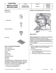
INSTALLATION
INSTRUCTIONS
PARTS LIST
Accessory
Application
RUNNING BOARDS
P/N 08L33-T0A-100B
2015 CR-V
Publications No.
VERSION 1
Issue Date
SEP 2014
16 Flange nuts
Left running board
Left front template
Right running board
Left rear template
Left trim
Right front template
Right trim
Right rear template
Wire tie
4
Brackets A
4
Brackets B
40 Flange bolts, 8 x 20 mm
© 2014 American Honda Motor Co., Inc. – All Rights Reserved.
22 Hole seals
2
AII 52391 (1409)
Sponge
08L33-T0A-1B00-90
1 of 14
TOOL AND SUPPLIES REQUIRED
INSTALLATION
Phillips screwdriver
Ratchet
10 mm and 13 mm Sockets
Torque wrench
Drill
3 mm, 6 mm, 8 mm, and 10 mm Drill bits
Blanket
Eye protection (safety goggles, face shield, etc.)
Utility knife
Pushpin
File
Ruler
Diagonal cutter
Isopropyl alcohol
Shop towel
The following tools are available through the Honda Tool
and Equipment Program. On the iN, click on: Service >
Service Bay > Tool and Equipment Program, then enter
the number under “Search”. Or, call 888-424-6857.
• Air Saw (T/N AT192A)
• Plastic Trim Tool (T/N SILTRIMTL10)
Customer Information: The information in this
installation instruction is intended for use only by skilled
technicians who have the proper tools, equipment, and
training to correctly and safely add equipment to your
vehicle. These procedures should not be attempted by
“do-it-yourselfers.”
NOTE:
• These instructions show the left running board being
installed. The same procedure applies to installing the
right running board.
• Do not damage the body paint finish.
• This kit should be installed only if the ambient air
temperature is 15°C (60°F) or above.
• To allow the adhesive to cure, do not wash the vehicle
for 24 hours. Please advise the customer.
1. Remove the self-tapping screws and clip from the left
front wheel arch protector.
LEFT FRONT WHEEL
ARCH PROTECTOR
Illustration of the Running Boards Installed on the
Vehicle
RIGHT RUNNING
BOARD
CLIP
FRONT
2 SELF-TAPPING
SCREWS
QCD0502AA
LEFT RUNNING
BOARD
QCD0501AA
2 of 14
AII 52391 (1409)
© 2014 American Honda Motor Co., Inc. – All Rights Reserved.
2.
Release the left front wheel arch protector.
2 CLIPS
5.
Release the left rear wheel arch protector.
LEFT REAR WHEEL
ARCH PROTECTOR
CLIP
LEFT FRONT WHEEL
ARCH PROTECTOR
2 RETAINING
TABS
FRONT
RETAINING
TAB
QCD0505AA
FRONT
6.
CLIP
LEFT SIDE
SILL TRIM
QCD0503AA
3.
Remove the clip from the left side sill trim.
4.
Remove the two self-tapping screws from the left
rear wheel arch protector.
Remove and discard the three clips from the left side
sill trim.
LEFT SIDE SILL
TRIM
FRONT
LEFT REAR WHEEL
ARCH PROTECTOR
3 CLIPS
(Discard.)
QCD0506AA
FRONT
2 SELF-TAPPING
SCREWS
QCD0504AA
© 2014 American Honda Motor Co., Inc. – All Rights Reserved.
AII 52391 (1409)
3 of 14
7.
Remove the left side sill trim.
12. Remove the canister pipe guard.
FRONT
8 CLIPS
(One clip is reused, and
seven clips are discard.)
LEFT SIDE SILL
TRIM
FRONT
3 BOLTS
QCD0507AA
8.
9.
CLIP
Remove the eight clips from the vehicle panel.
Repeat steps 1 through 8 on the right side of the
vehicle.
CANISTER
PIPE GUARD
Q0D2703CB
13. Remove the right under cover.
10. Raise the vehicle off the ground and support it in the
proper locations as described in the Service Manual.
FRONT
FRONT
2 BOLTS
2 CLIPS
RIGHT UNDER
COVER
4 CLIPS
3 BOLTS
QA10601BB
5 CLIPS
2 CLIPS
LEFT UNDER
COVER
Q0D2702DB
11. Remove the left under cover.
4 of 14
AII 52391 (1409)
© 2014 American Honda Motor Co., Inc. – All Rights Reserved.
14. Align and attach the left front template and left rear
template to the under cover with the masking tape as
shown.
15. Using a pushpin, pierce all six marks in the
templates.
PUSHPIN
LEFT UNDER
COVER
LEFT REAR
TEMPLATE
CROSS SECTION
LEFT UNDER
COVER
LEFT REAR
TEMPLATE
LEFT UNDER
COVER
Align.
6 MARKS
LEFT REAR
TEMPLATE
Align.
LEFT UNDER
COVER
PUSHPIN
LEFT UNDER
COVER
MASKING
TAPES
LEFT UNDER
COVER
FRONT
LEFT FRONT
TEMPLATE
FRONT
CROSS SECTION
6 MARKS
LEFT FRONT
TEMPLATE
LEFT FRONT
TEMPLATE
QA40802BD
16. Remove the templates.
LEFT UNDER
COVER
Align.
Align.
LEFT UNDER
COVER
© 2014 American Honda Motor Co., Inc. – All Rights Reserved.
QA40801BD
AII 52391 (1409)
5 of 14
17. While wearing eye protection, drill the twelve holes to
10 mm. First drill with a 3 mm drill bit, and then with
a 6 mm drill bit, with an 8 mm drill bit, and finish with
a 10 mm drill bit.
NOTE: Do not damage the insulator when drilling the
left under cover.
DRILL
18. While wearing eye protection and using an air saw,
cut the left under cover as shown. Remove any burrs.
NOTE: Do not damage the insulator when cutting the
left under cover.
LEFT UNDER
COVER
LEFT UNDER
COVER
FRONT
Cut.
3 mm 6 mm
8 mm 10 mm
DRILL BITS
Cut.
AIR SAW
Cut.
6 HOLES
AIR SAW
Cut.
QA40804BD
19. Peel the insulator as shown.
DRILL
Do not peel.
VIEWED FROM TOP SIDE
LEFT UNDER
COVER
LEFT UNDER
COVER
3 mm
6 mm
8 mm
10 mm
DRILL
BITS
FRONT
6 HOLES
QA40803BD
Do not peel.
RIGHT UNDER
COVER
INSULATOR
INSULATOR
(Peel.)
FRONT
QA61503BB
6 of 14
AII 52391 (1409)
© 2014 American Honda Motor Co., Inc. – All Rights Reserved.
20. Using a pushpin, pierce the right under cover as
shown.
22. Roll up the insulator, and secure it to the right under
cover with one wire tie.
Do not peel.
FRONT
PUSHPIN
VIEWED FROM TOP SIDE
HOLE
Do not peel.
25 mm
(1.0 in.)
RIGHT UNDER
COVER
RIGHT UNDER
INSULATOR
COVER
WIRE TIE
INSULATOR
(Roll up.)
QA61501AB
21. While wearing eye protection, drill one mark to 10
mm. First drill with a 3 mm drill bit, and then with a 6
mm drill bit, with an 8 mm drill bit, and finish with a
10 mm drill bit. Remove any burrs.
FRONT
DRILL
FRONT
HOLE
(Made in
step 21.)
HOLE
QA61504BB
3 mm 6 mm
8 mm 10 mm
DRILL BITS
RIGHT UNDER
COVER
MARK
QA61502AB
© 2014 American Honda Motor Co., Inc. – All Rights Reserved.
AII 52391 (1409)
7 of 14
23. Align and attach the right front template and right
rear template to the right under cover with masking
tapes.
24. Using a pushpin, pierce six marks on the each
templates.
PUSHPIN
RIGHT FRONT RIGHT UNDER
COVER
TEMPLATE
CROSS SECTION
RIGHT UNDER
COVER
RIGHT FRONT
TEMPLATE
Align.
6 MARKS
RIGHT FRONT
TEMPLATE
Align.
RIGHT UNDER
COVER
PUSHPIN
RIGHT UNDER
COVER
FRONT
RIGHT REAR
TEMPLATE
RIGHT UNDER
COVER
MASKING
TAPES
CROSS SECTION
RIGHT REAR
TEMPLATE
FRONT
RIGHT REAR
TEMPLATE
6 MARKS
QA40806BD
25. Remove the templates.
Align.
RIGHT UNDER
COVER
8 of 14
RIGHT UNDER
COVER
Align.
QA40805BD
AII 52391 (1409)
© 2014 American Honda Motor Co., Inc. – All Rights Reserved.
26. While wearing eye protection, drill the twelve holes to
10 mm. First drill with a 3 mm drill bit, and then with
a 6 mm drill bit, with an 8 mm drill bit, and finish with
a 10 mm drill bit.
NOTE: Do not damage the insulator when drilling the
right under cover.
RIGHT UNDER
COVER
27. While wearing eye protection and using an air saw,
cut the right under cover as shown. Remove any
burrs.
NOTE: Do not damage the insulator when cutting the
right under cover.
FRONT
DRILL
Cut.
RIGHT UNDER
COVER
Cut.
3 mm 6 mm
8 mm 10 mm
DRILL BITS
6 HOLES
AIR SAW
Cut.
DRILL
Cut.
AIR SAW
QA40808BD
28. Using isopropyl alcohol, thoroughly clean the under
side where the hole seals will attach.
RIGHT UNDER
COVER
3 mm 6 mm
8 mm 10 mm
DRILL BITS
Clean with
isopropyl
alcohol.
FRONT
FRONT
RIGHT UNDER
COVER
6 HOLES
QA40807BD
ADHESIVE
3 HOLE SEALS BACKINGS
(Remove.)
QCD0615AA
29. Remove the adhesive backing from each hole seal,
and attach the seal over the holes as shown.
© 2014 American Honda Motor Co., Inc. – All Rights Reserved.
AII 52391 (1409)
9 of 14
30. Using isopropyl alcohol, thoroughly clean the body
where the hole seals will attach.
33. Install the spring nut removed in step 32 to the left
trim.
SPONGE
(Discard.)
CLIP
ADHESIVE
BACKINGS
(Remove.)
NEW
SPONGE
Clean with
isopropyl
alcohol.
LEFT
TRIM
CLIP
FRONT
7 HOLE SEALS
QCD0616AA
31. Remove the adhesive backing from each hole seal,
and attach the seal over the holes as shown.
32. Remove the spring nut from the left side sill trim.
SPRING NUT
LEFT SIDE SILL
TRIM
(Discard.)
QCD0617AA
34. Remove and discard the sponge from the clip
removed in step 8.
35. Install the new sponge to the clip, and attach the clip
to the left trim.
36. Install the left trim to the vehicle panel with one clip
removed in step 3.
LEFT FRONT WHEEL
ARCH PROTECTOR
SPRING NUT
QAD2017AB
LEFT
TRIM
FRONT
10 of 14
AII 52391 (1409)
CLIP
QCD0901AA
© 2014 American Honda Motor Co., Inc. – All Rights Reserved.
37. Reinstall the left front wheel arch protector.
42. Insert the two brackets B into the holes on the left
under cover as shown.
LEFT FRONT WHEEL
ARCH PROTECTOR
LEFT UNDER
COVER
HOLE
BRACKET B
FRONT
BRACKET B
VEHICLE
PANEL
CLIP
LEFT
TRIM
2 SELFTAPPING
SCREWS
FRONT
QCD0902AA
38. Secure the left trim to the vehicle panel with one
self-tapping screw removed in step1.
39. Secure the left front wheel arch protector to the left
front inner fender with one self-tapping screw and
clip removed in step1.
2 FLANGE
BOLTS,
8 x 20 mm
(Loosely
secure.)
2 FLANGE BOLTS,
8 x 20 mm
(Loosely secure.)
40. Loosely secure the bracket A to the bracket B using
the four 8 x 20 mm flange bolts and four flange nuts.
BRACKET A
BRACKET B
LEFT
UNDER QCD0904AA
COVER
43. With help from an assistant place the left under cover
close to the vehicle and loosely install the two
brackets B to the vehicle panel using four
8 x 20 mm flange bolts.
BRACKET B
4 FLANGE BOLTS,
8 x 20 mm
4 FLANGE NUTS
QCD0903AA
41. Repeat the same procedure for the other bracket A
and bracket B.
© 2014 American Honda Motor Co., Inc. – All Rights Reserved.
AII 52391 (1409)
11 of 14
44. Loosely secure the two brackets A to the vehicle
panel using four 8 x 20 mm flange bolts.
BRACKET A
VEHICLE
PANEL
45. With help from an assistant, loosely secure the left
running board to the two brackets A using four 8 x 20
mm flange bolts.
FRONT
FRONT
BRACKET A
LEFT RUNNING
BOARD
2 FLANGE BOLTS,
8 x 20 mm
(Loosely secure.)
2 FLANGE BOLTS,
8 x 20 mm
(Loosely secure.)
4 FLANGE
BOLTS,
8 x 20 mm
(Loosely
secure.)
QCD0905AA
CROSS
SECTION
LEFT RUNNING
LEFT RUNNING
BOARD
BOARD
QCD0906AA
BRACKET A
BRACKET A
12 of 14
AII 52391 (1409)
© 2014 American Honda Motor Co., Inc. – All Rights Reserved.
46. Secure the two brackets B to the vehicle panel.
Torque the flange bolts: 22 N·m (2.2 kgf·m, 16 lbf·ft).
2 FLANGE BOLTS,
8 x 20 mm,
22 N·m (2.2 kgf·m,
16 lbf·ft)
48. Secure the two brackets A to the two brackets B.
Torque the flange bolts: 22 N·m (2.2 kgf·m, 16 lbf·ft).
SIDE VIEW
VEHICLE
PANEL
BRACKET B
FRONT
FRONT
8 x 20 mm
FLANGE
BOLT
BRACKET A
Adjust to the parallel.
VEHICLE
PANEL
LEFT
UNDER
COVER
2 FLANGE BOLTS,
8 x 20 mm,
22 N·m (2.2 kgf·m,
16 lbf·ft)
QCD0907AA
4 FLANGE BOLTS,
8 x 20 mm,
22 N·m (2.2 kgf·m,
16 lbf·ft)
47. Secure the two brackets A to the vehicle panel.
Torque the flange bolts: 22 N·m (2.2 kgf·m, 16 lbf·ft).
2 FLANGE BOLTS,
8 x 20 mm,
22 N·m (2.2 kgf·m,
16 lbf·ft)
BRACKET A
VEHICLE
PANEL
FRONT
2 FLANGE BOLTS,
8 x 20 mm,
22 N·m (2.2 kgf·m,
16 lbf·ft)
© 2014 American Honda Motor Co., Inc. – All Rights Reserved.
4 FLANGE BOLTS,
8 x 20 mm,
QCD0909AA
22 N·m
(2.2 kgf·m, 16 lbf·ft)
49. Secure the left running board to the two
brackets A. Torque the flange bolts: 22 N·m
(2.2 kgf·m, 16 lbf·ft).
2 FLANGE BOLTS,
8 x 20 mm,
22 N·m (2.2 kgf·m,
16 lbf·ft)
LEFT
UNDER
COVER
LEFT
UNDER
COVER
VEHICLE
PANEL
FRONT
BRACKET A
QCD0908AA
LEFT
UNDER
COVER
AII 52391 (1409)
2 FLANGE BOLTS,
8 x 20 mm,
22 N·m (2.2 kgf·m,
16 lbf·ft)
QCD0910AA
13 of 14
50. Install the left rear wheel arch protector.
52. Visually check that the left running board is installed
parallel to the vehicle.
LEFT RUNNING
BOARD
LEFT RUNNING
BOARD
FRONT
FRONT
LEFT REAR WHEEL
ARCH PROTECTOR
QCD0911AA
51. Secure the left running board to the left rear wheel
arch protector with two self-tapping screw removed
in step 4.
Parallel.
LEFT RUNNING
BOARD
Parallel.
LEFT REAR WHEEL
ARCH PROTECTOR
LEFT RUNNING
BOARD
QCD0913AA
53. Repeat steps 28 through 52 on the right side of the
vehicle.
54. Reinstall all removed parts.
FRONT
2 SELF-TAPPING
SCREWS
QCD0912AA
14 of 14
AII 52391 (1409)
© 2014 American Honda Motor Co., Inc. – All Rights Reserved.