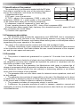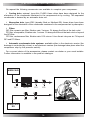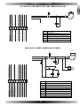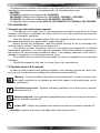
1
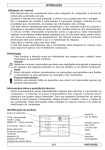
The Manufacturer declares under his/her own responsibility that the air electrocompressors
described in this manual are in compliance with the following safety rules:
98/37/EEC
72/23/EEC (modified and integrated by: 93/68/EEC)
89/336/EEC (modified and integrated by: 92/31/EEC - 93/68/EEC - 93/97/EEC)
87/404/EEC (modified and integrated by: 90/488/EEC - 93/68/EEC)
in compliance with the harmonized: EN1012-1/96, EN60204-1/97, EN50081-1/92, EN500822/95, EN50082-2/95.
1.1 How to use this instructions manual
• This manual is an integral part of your compressor and shall be kept with it for future
reference. Should your compressor be resold, entrust it to the new owner who will obviously
need the information contained.
• Keep this manual in a suitable place within the operator’s reach and be sure it is in a
safe place protected by any agents which might damage it.
• Before starting the compressor, read this manual carefully so as to understand the
contents clearly; consult it whenever any doubt arise.
• This manual contains information useful for your safety and instructions to facilitate
maintenance operations or to clarify special operations. Follow the indication contained in it
and perform the recommended procedures which, if not properly observed, could result in
damage to equipment or could cause personal injury.
• This manual does not include the spare parts list, which is available by our Authorized
Resellers.
• Should this manual be lost, ask for a new copy to the manufacturer.
1.2 Symbols used in this manual
In order to make evident some special information, the following symbols are used: however you are not relieved from reading the instructions manual carefully.
Warning- It refers to safety instructions to be complied with in order to ensure maximum safety conditions to the operator as well as to people in the working area, and to
the compressor.
Specialized personnel - Symbols indicating operations to be carried out by specialized personnel only.
Machine stopped - Every operation highlighted by this symbol must only be carried out
with the machine powered off.
Power OFF - Before any operation the machine should be necessarily powered off.
Important: symbols at the top of the page refer to the whole section.
65
ENGLISH
1. MAIN INFORMATION
1. MAIN INFORMATION
1.3 Identification of the product
The product that you purchased is marked with the EC plate.
1
2
Such plate is reported on the cover of this instruction manual
3
and on the compressor, and shows the following data:
1) Manufacturer’s data
4
5
2) EC mark - year of construction
6
7
3) TYPE = name of the compressor, CODE = code of the
compressor, SERIAL N. = serial number of the compressor
(to be quoted when asking for the Service Assistance)
4) compressor output air measured in (l/min) and (cfm)
5) max. operating pressure (bar and PSI) - noise of the compressor dB(A)
6) electric data: power supply (V/ph), frequency (Hz), absorbed current (A) - power (HP and
kW), revolutions per minute (Rpm).
7) Possible other approvals.
1.4 Compressor description
• Our OILLESS series includes the compressors mod. MEDICAIR, that is compressors
which do not need any lubricants to run. Such peculiarity ensures a very easy use and reduced ordinary service. Moreover, such feature allows working even on inclined plane without
jeopardizing the proper operation of the machine.
The range of the models includes versions with drier and soundproof cabin.
• The main components of your compressor are shown in the information table enclosed
to this instruction manual. Such table includes the max. overall dimensions of the compressor, and the main spare and wear parts.
1.5 Guarantee
• This product is tested and guaranteed for a period of 12 months from the date of
delivery.
• This guarantee is limited to all clients who have fulfilled all contractual and administrative obligations and who have installed and operated the product in compliance with the
instructions provided in this manual.
• Under the terms of this guarantee, the Manufacturer shall repair or replace free of
charge all components which are proved to be defective at source. The Manufacturer’s Technical Assistance Service shall be the sole authority in determining whether or not defects
come under the coverage of the guarantee.
• The guarantee does not cover labour costs for technical service operations, which will
be duly charged.
• The guarantee also excludes all responsibility on the part of the Manufacturer for direct
or indirect loss or damage to persons or things deriving from incorrect operation or servicing
of the product and is limited to defects in material or assembly.
• The guarantee excludes all components subject to normal wear.
• Furthermore, the guarantee excludes all costs for transport, inspection, removal and
reassembly incurred by the Manufacturer’s service personnel when faults are not imputable
to the Manufacturer.
66
2.1 Main features
Among the most important features, the following should be noted:
inner tank walls coated with rustproof paint,
inner rings made of special friction-free material,
aluminium piston coated with special friction-free material,
absorption drier with cleaning automatic cycle,
ergonomic guards with anti-shock handle,
pressure switch / remote pressure switch with integrated starter/stop switch,
non-return and safety valves,
overload cutout and cooling fan,
cock for condensate drainage,
single- and three-phase motors, 230 and 400 V.
2.2 Technical data
See data on EC plate, according to section 1.3.
2.3 Safety devices
•
•
Pressure switch (fig. 5): adjusts both STOP and START pressure.
Safety valve: after reaching the max. pressure value it releases the air off.
•
Compressors with single-phase electric motor are equipped with overload cutout (fig. 6) which operates as a safety device in case of motor overload. When the motor
overheats because of any fault arisen, the overload cutout automatically releases and
cuts off power, thus preventing the motor from being damaged. Wait a few minutes
(about 5) before resetting the device, then restart the motor.
If you restart the compressor and the overload cutout releases again, turn the main switch
to position (0) unplug the equipment and contact any Authorized Service Centre.
Compressors with three-phase electric motor are equipped with remote pressure switch
(Fig.5), i.e. the overload cutout into the remote pressure switch operates to protect the motor,
and stops the compressor in case of motor overload by turning automatically the starter
switch to position (0). In that case, cut off power and manually reset the thermal relay inside
the electric box (Fig.6A).
If you restart the compressor and the device releases again, turn the main switch to position “0” OFF, and contact any Authorized Service Centre for correct relay setting and, if necessary, for any adjustments.
• Exhaust solenoid valve: when the power is cut off, the solenoid valve opens and releases all the air in the head of the compressor unit and in the delivery hose.
2.4 Standard accessories supplied (Fig. 3)
The following accessories are supplied together with the compressor:
a. Operation and Service Manual + information table,
b. anti-vibrating feet,
67
ENGLISH
2. TECHNICAL FEATURES
3. SAFETY GENERAL WARNINGS
3.1 General information
•
Your compressor was thought, manufactured and arranged for being used as a
compressed air source solely, according to the safety instructions described hereunder.
•
Several pneumatic accessories can be connected to your compressor. For a
proper use, refer to their single user’s manual.
• Before operating your compressor or performing any operation read this Manual very
carefully.
• Any change, tampering or different use from what reported in the instruction manual is
forbidden. The Manufacturer assumes no responsibility for any damages resulting from
improper use or noncompliance with the instructions described in this manual.
• Before carrying out any service operation to your compressor, ensure the power has
been cut off by turning off the main switch and the wall switch (when supplied).
3.2 What YOU MUST DO:
Check that mains voltage is the same as voltage written on the EC plate.
Learn how to stop the compressor suddenly and how to use all controls.
Before carrying out any service operation the compressor tank must be emptied.
Unplug the compressor so as to prevent any sudden unexpected restart.
After any maintenance operation, make sure all components have been fitted correctly.
Keep out children or animals from the operating area so as to prevent damages or injuries
caused by any accessory connected to your compressor.
Read carefully the instructions on the fitted accessory.
Provide for protection against accidental contacts by automatic power cut off, taking into
consideration that the compressor is of class I and is equipped with connection to the earth.
3.3 What YOU MUST NOT DO:
Do not touch the cylinder heads, the cooling fins and the feed pipe. During operation,
because of the high temperature achieved, those parts keep hot for a certain time even
after switching off the compressor.
Do not leave inflammable, nylon objects or cloths near the compressor.
Do not move the compressor with the tank under pressure.
Do not use the compressor with the supply cord damaged or with precarious connection.
Do not use the compressor in potential explosive environment or near free flames.
Do not use the compressor in humid or dusty areas.
Do not direct the air jet towards people or animals.
Do not allow anybody to operate the compressor unless he/she has received correct instructions.
Do not hit fans with metal or blunt objects as they could break during operation.
Do not operate the compressor without air filter.
Do not tamper the safety and adjusting devices.
68
4.1 Compressor unpacking and handling (Fig. 1)
Make sure both the machine and all supplied accessories are perfectly safe and undamaged.
When delivered, the machine is on a wooden pallet and protected by a top cardboard
packing.
Wear safety gloves and cut the outer straps and withdraw the cardboard from the top, then
unscrew the nuts which lock the compressor.
Warning: compressors equipped with drier tend to bend because of the weight on the
rear side. Balance the unit before lifting it.
•
Compressor with 24-litre tank: size the compressor by the handles with the help
of another person, then lift it.
• Compressor with tank over 24 litres: Lift the compressor with a fork truck of suitable
capacity (see the information table), by fitting the forks through the tank supporting feet and
fitting a wooden bar perpendicular so as to prevent the compressor from shifting during
lifting.
Fit anti-vibrating elements (Fig. 2).
Packing disposal
Save the packing material in case you ever need to transport the compressor in the future.
We recommend that you store the packing in a safe location, at least within the period of the
guarantee. In case of need, it will be easier to send the compressor to the service centre.
Afterwards, put it into the care of the company or board in charge of elimination.
4.2 Positioning
As previously said all compressors can work properly even on an plane with a transversal
or longitudinal inclination over 15°.
In order to ensure proper air flow, position and fit the compressor so as to leave the
ventilation grill at least at 20 cm from any obstacles which may prevent air from flowing
out correctly, and so as to facilitate maintenance and cleaning operations.
When choosing the room of installation of your compressor, make sure that the installation
place meets all the safety standards in force in the country in which the compressor is used,
and that the following conditions are respected:
• low room dust percentage,
• the working room should be large enough to allow the room temperature to be kept
within 40° when the machine is running.
If the above requirement cannot be met, fit one or more exhausters for the hot air. Fit the
highest number possible for the working room.
4.3 Electric connection
All compressors are delivered only after a successful testing period at the factory and
are ready to use.
Before performing the electric connection, you must check that the mains power corresponds to the power data written on the EC label and that the main SWITCH is turned to (0).
SINGLE PHASE COMPRESSORS: the compressor is equipped with a Schuko plug (Fig.4).
If necessary, contact specialized personnel for plug replacement.
69
ENGLISH
4. INSTALLATION
4. INSTALLATION
THREE-PHASE COMPRESSORS: it is necessary to provide the supply line with a
magneto-thermal switch of suitable capacity respect to the installed power (Fig.4). To
such purpose, follow the indications written in the table.
Compressor power (see EC plate)
Absorbed power
Direct start relay adjustment
Power cable min. cross section
Wall switch capacity
CV
A
A
mm²
A
2.5
12
15
2.5
16
5 (2×2.5CV)
24
15+15
4
32
5. ADJUSTMENTS
5.1 Timing and operation modes
• All compressors, apart from TANDEM models can work in just one mode, i.e. the “classic” automatic mode controlled by the pressure switch/ remote pressure switch, which stops
the compressor when the max. pressure is reached, and starts the compressor again when
pressure decreases by 1.5 bar.
• For TANDEM models the operation mode must be set according to the quantity of
compressed air needed. We recommend that you contact your usual installer bearing in
mind the compressed air output necessary for your work, and the air output value written in
the EC plate.
These models can work either with both the units or with only one unit, and the operation
mode is controlled by an electronic board (Fig. 7).
You can select among the following operation modes:
• Cycle M1-M2: alternated operation of the two pumping units.
• Cycle M1: operation of the sole pumping unit M1.
• Cycle M2: operation of the sole pumping unit M2.
• Cycle M1+M2: simultaneous operation of the two pumping units.
5.2 Pressure adjustment
Have a pressure reducer installed on the delivery line of compressed air by a specialised technician.
For correct use, check pressure correct value. Refer to the user’s manual of the tool
concerned for the working pressure setting.
By the pressure reducer adjust output air pressure to the desired value.
After having used your compressor, set pressure to zero, so as to avoid damaging the
pressure reducer.
5.3 Controls and check devices
In order to identify the parts listed hereunder, see the product sheet enclosed to the instruction manual.
• Pressure switch/remote pressure switch: checks compressor start and stop.
• Tank pressure gauge: shows the pressure inside the air tank .
• Line cock: detecting and connecting device to detect and connect the line and/or the
pneumatic tools.
• Electronic controller (Tandem versions): checks start and stop of the compressor, and
allows selecting the operation mode (fig.7).
70
START
STOP
ON
OFF
AIR
ENGLISH
5. ADJUSTMENTS
M1
M2
ESS
Main switch
turn-off switch
green led =running machine
red led = stopped machine
system mode
led OFF=correct pressure
led ON=low pressure
M1 unit activated
M2 unit activated
drier outlet activated
M1-M2
M1
M2
M1+M2
alternated operation of the two pumping units M1 and M2
operation of the sole pumping unit M1
operation of the sole pumping unit M2
simultaneous operation of the two pumping units
5.4 Operation set-up (Tandem models only)
Before starting the compressor, it is necessary to set some parameters.
4 switches are located on the rear side of the control board (fig.7a), and have the
following functions:
SW1
SW2
SW3
SW4
ON position - it enables the automatic re-start of the compressor in case of
power failure
OFF position - the compressor re-starts only by pressing the START key
ON position - the compressor re-starts after 3 minutes of low pressure
OFF position - the compressor re-starts after 1 minute of low pressure
ON position - delayed stop. Press the STOP key: the compressor stops when
the line pressure value is reached. The stop cycle is signalled by the flashing red
led OFF. This function is useful to avoid the risk of the compressor re-start with
the head under pressure. In such case, when reaching the line pressure value is
achieved, the exceeding air is blown off.
OFF position - Immediate stop after pressing the STOP key.
Recommended only when the compressor head is equipped with blowing off
valve.
SW4 switch is in position OFF at the delivery of the compressor.
DO NOT CHANGE THIS SETTING, IN ANY CASE, but, if necessary contact an
Authorized Service Centre.
71
6. OPERATION AND USE
6.1 Mode of Operation (Tandem models) (Fig. 7)
In order to select the operation cycle, press the STOP button for at least 4 seconds to
activate the different programmes (the corresponding green led will light up) at an interval of
½ second. After selecting the desired programme, release the STOP button. The selected
programme will be kept stored in the memory even in case of power failure.
• Cycle M1-M2: alternated operation of the two pumping units.
SW2 function is active only when this mode is selected, so, depending on your air consumption, adjust the switch in position ON (low consumption) or OFF (high consumption).
When the line pressure value is reached, both the pumping units stop, then they start again
when the pressure value decreases.
• Cycle M1: operation of the sole pumping unit M1.
• Cycle M2: operation of the sole pumping unit M2.
NOTE: If just one unit is used, as usually happens, do not use always the same unit but let
the work be shared fairly by both of them.
• Cycle M1+M2: simultaneous operation of the two pumping units.
The first unit M1 starts and after about 10 seconds starts the unit M2; they both work
together and stop when the line pressure value is reached, then they start again when the
pressure value decreases.
NOTE: Please remember to start both units together only if a big amount of compressed air is needed because under these conditions, and especially at the start-up,
high electrical input peaks may occur.
For the most appropriate operation cycle, contact your usual installer, taking into account
your compressed air consumption and the data written on the EC label of the compressor.
6.2 Operation cycle
The compressor runs completely automatically by the pressure switch, which stops the
compressor when the max. pressure value is reached and restarts the compressor only
when this value has decreased to the minimum value accepted.
TANDEM compressors operate in automatic mode however, the operation depends on the
setting selected according to your requirements.
The air circuit follows the diagrams: compressor, heat exchanger with condensate separator and automatic drain, absorption drier, tank and filter.
• The two drier “chambers” work one at a time (Fig. 8):
compressed air from the tank comes to chamber (1) and it is forced through several
alumina layers which absorb the humidity in the air. Therefore, when coming out the air is
“dry”. A small amount of air is not used by sent to chamber (2) where it absorbs humidity, thus
regenerating the alumina layers. The small amount of air used comes off from the solenoid
valve at the base of the drier. An air blow of some minutes means that the compressor is
working properly.
72
6.3 First start-up
• Make sure the switch is in position "0”.
• Plug in the compressor (single-phase model) or power the unit by the wall-mounted
main switch (three-phase model).
Single models
Start up the compressor by turning the pressure switch / remote pressure switch to position (1) (fig.5).
Tandem models
Turn the switch to position (1) (fig.7).
Press the START button to start the compressor, the led ON will light up (steady light = the
selected operation cycle is activated, flashing light = system under pressure). The pressure
switch activates the AIR signal which shows the status of the system.
When the ESS led lights up, the drier starts operating.
• When starting your compressor for the first time, make the compressor run for about ten
minutes with the air cocks open. Then close the cocks and make sure that the compressor
is running until the max. pressure allowed and shown on the EC plate appears on the
pressure gauge.
In order to stop the compressor, turn the switch fitted on the machine.
73
ENGLISH
6. OPERATION AND USE
7. MAINTENANCE AND DISPOSAL
• In order to keep your compressor in good working conditions we recommend you to
perform periodical servicing operations. Before performing any maintenance operation, switch
off the compressor and make all air in the tank release.
• For the soundproof models, it is necessary to remove the upper case to access the
compressor unit. Use a 6-mm Allen spanner to unscrew the four screws which fasten the
case.
When removing compressor case, make sure “do not tear” the supply cable of the
cooling fan.
• After the first 50 working hours, check all screw tightening, and especially head and
base screws (Fig. 9).
7.1 Condensate drainage (weekly) (Fig. 10)
For models without drier and automatic condensate drain.
Place a container under the drain valve and open the cock by turning it anti-clockwise.
As our “Oilless” series compressors do not require lubricant, the condensate flowing
out the tank is not polluted and can be eliminated through the sewer system.
7.2 Cleaning the suction filter (monthly) (Fig. 11)
These models have one or two suction filters next to the compressor head. To open,
unscrew the middle screw.
Take out the filtering component and rinse with water and soap.
Dry completely and refit. Close the filter.
Do not operate the compressor without the suction filter fitted, as foreign bodies or dust
could seriously damage the inside components.
7.3 Further servicing
• Every 6 months or 500 working hours
It recommended to clean carefully all finned parts of the compressor. In this way the cooling
system is kept efficient and ensures a better performance of the compressor (Fig. 9).
• Every year or 1000 working hours
Change the filtering component (follow the instructions written in section § 7.2).
• Every 2 years or 2000 working hours
1) Check and clean the suction and delivery valves
2) Check the non-return valve and replace the seal D, if necessary (Fig.12).
When you perform the above operations, we recommend to replace the relevant seals.
• At least every 3 years, replace the alumina contained in the drier. Such time span has
been determined by supposing an average use of the compressor (i.e. 2 hours a day); in
case of a more intense activity, have the air humidity rate checked by a specialised technician
and, if necessary, replace alumina in advance.
USE ONLY FINI ORIGINAL SPARE PARTS, AVAILABLE AT ALL FINI AUTHORIZED SERVICE
CENTRES. IMITATION SPARE PARTS MAY DAMAGE YOUR COMPRESSOR IRREPARABLY.
74
Summary of the maintenance operations
Weekly
Monthly Every 6 months Every year Every 2 years Every 3 years
or 500 hours
Drain condensate
X
Clean suction filter
Clean finned parts
Replace the filtering component
Check and clean
suction and delivery valves
Check and clean non-return valve
Replace alumina
or 1000 h.
or 2000h.
X
X
X
X
X
X
7.4 Compressor disposal
In case you need to get rid of your compressor, it is compulsory to get rid of all the parts and
components according to the laws in force. In any case, contact the company or board in
charge of elimination.
8 . TROUBLESHOOTING
Fault
Cause
Remedy
The pressure switch valve
leaks when the compressor
is idle
Non-return valve seal Make air in the tank flow out (Fig.
defective
10), then remove the non-return
valve plug and clean the seat and
the seal (Fig. 12).
If necessary replace the seal.
The pressure switch valve
leaks when the compressor
is running
Failure of empty-start
valve
The compressor stops and
does not start
Overload cutout operated Cut off voltage and press the
because of motor overheating button to start (Fig.6/6a).
Replace the valve (Fig. 5)
Winding burnt out
Contact a specialized technician
The compressor stops after
reaching the max. pressure
and the safety valves operates
Wrong operation or
pressure switch broken
Contact a specialized technician
The compressor does not
reach the set pressure and
overheats too much
Compressor head gasket
broken or valve faulty
Stop the compressor immediately and contact a specialized
technician.
The compressor is noisy with
metallic clangs
Bearing seizure
Stop the compressor immediately and contact a specialized
technician.
75
ENGLISH
7. MAINTENANCE AND DISPOSAL
9. ACCESSORIES AVAILABLE ON REQUEST
On request the following accessories are available to complete your compressor:
• Cooling drier, external, type Artic 134/05: these driers have been designed for the
elimination of the condensate contained in the compressed air by cooling. The separated
condensate is drained by an automatic drain unit.
• Absorption drier type AF02 (already fitted on Medicair-ES): these driers have been
designed for the elimination of the condensate contained in the compressed air by absorption.
•
Filters
QFI filter, ceramic pre-filter, filtration rate: 3 micron. Fit always the filter at the tank oulet.
PFI filter, oil separator, filtration rate: 1micron. Fit always the filter at the tank oulet or beyond
the QFI filter.
CFI filter, coalescenze filter, filtration rate: 0.01 micron. It turs the air into pure air. Fit beyond
QFI and PFI filters.
• Automatic condensate drain systems: available either in the electronic version (the
drainage is controlled by a timer) or not electronic version (the drainage takes place when the
compressor stop by the pressure switch).
For a correct choice of the accessories, please contact our dealer or your usual installer.
Further information is available in the product catalogue.
MEDICAIR
QFI
ARTIC
PFI
PFI
CFI
CFI
MEDICAIR
ES
76
TService pressure switch earth
Drier electro-fan power
From service pressure switch
Drier electro-fan power
From service pressure switch
Drier electro-fan power
Power neutral
Drier electro-fan power
Head solenoid valve earth
To the head solenoid valve
To the compressor motor
To the head solenoid valve
To the compressor motor
To service pressure switch
To service pressure switch
Compressor motor earth
P
Power phase
Service pressure switch earth
From service pressure switch
From service pressure switch
Power neutral
Power phase
Power earth
Head solenoid valve earth
To the head solenoid valve
To the compressor motor
To the head solenoid valve
To the compressor motor
To service pressure switch
To service pressure switch
Compressor motor earth
OL 102-24F-0,75M / MK150-24F-1,5M / VKM300-50F-2,5M
S
Ref.
MC
S
Y
F
C
N
Ref.
MC
Mv
Mt
F
F1
S
Y
Y1-Y2
C
77
C
L
L1
N
N1
Y1
L1
N1
L
L1
N
N1
F
PE
S
N1
L1
L
Mt
1
Y2
N
PE L L N N L1 L1 N1N1
Description
Compressor motor
Drier fan motor
Drier timer motor
Compressor motor cut-out
Drier electro-fan cut-out
Service pressure switch
Head solenoid valve
Drier solenoid valves
Compressor motor condenser
F
PE
ENGLISH
P
Power earth
10. WIRING DIAGRAMS
MC
1
Y
PE L L N N L1 L1 N1N1
Description
Compressor motor
Service pressure switch
Head solenoid valve
Compressor motor cut-out
Compressor motor condenser
MK150-24F-1,5M ES / VKM300-50F-2,5M ES
C
MC
1
Y
F1
Mv
1
Service pressure switch earth
Drier electro-fan power
From service pressure switch
Drier electro-fan power
From service pressure switch
Drier electro-fan power
Power neutral
Drier electro-fan power
Head solenoid valve earth
To the head solenoid valve
To the compressor motor
To the head solenoid valve
To the compressor motor
To the inner fan motor
To service pressure switch
To inner room thermostat
To service pressure switch
Compressor motor earth
P
Power phase
Service pressure switch earth
From service pressure switch
From service pressure switch
Power neutral
Power phase
Power earth
Head solenoid valve earth
To the head solenoid valve
To the compressor motor
To the head solenoid valve
To the compressor motor
To the inner fan motor
To service pressure switch
To inner room thermostat
To service pressure switch
Compressor motor earth
P
Power earth
10. WIRING DIAGRAMS
Dr.Sonic OL 102-24F / Dr.Sonic MK150-24F / Dr.Sonic VKM300-50F
S
Ref.
MC
Mvi
F
F1
ST
S
Y
C
Y1
PE L L N N L1 L1N1N1
Ref.
MC
Mv
Mt
Mvi
F
F1
F2
ST
S
Y
Y1-Y2
C
78
C
L
L1
N
N1
L
L1
N
N1
F
PE
ST 40±5°C
S
N1
L1
L
N
ST
40±5°C
F
PE
Mt
1
MC
1
Y
F1
PE L L N N L1 L1N1N1
Mvi
1
Description
Compressor motor
Inner fan motor
Compressor motor cut-out
Inner fan cut-out
Inner room thermostat
Service pressure switch
Head solenoid valve
Compressor motor condenser
Dr.Sonic MK150-24F- ES / Dr.Sonic VKM300-50F-ES
C
MC
1
Y
F1
Mv
1
Y2
N
F2
Mvi
1
Description
Compressor motor
Drier fan motor
Drier timer motor
Inner fan motor
Compressor motor cut-out
Drier electro-fan cut-out
Inner fan cut-out
Inner room thermostat
Service pressure switch
Head solenoid valve
Drier solenoid valves
Compressor motor condenser
Control board Dr.Sonic 600 - V. 400 Hz. 50/60
Power earth (PE)
Serv. pres. switch earth(S)
M2 motor earth
M1 motor earth
Service pressure switch
Comp. 2 inner fan
Comp. 1 inner fan
Comp. 2 head drain sol. valve (Yt2)
Comp. 1 head drain sol. valve (Yt1)
FUSE
FUSE
FUSE
FUSE
2A
2A
4A
4A
(F6)
(F5)
(F4)
(F3)
Ref.
QS
F3-F4
F5-F6
F7-F8
ST1-ST2
Mv1-Mv2
M1-M2
K1
K2
F1+S1
F2+S2
S
D
H
Yt1+Yt2
Description
Door lock main switch
Ceramic fuse 5x20 4A
Ceramic fuse 5x20 2A
Inner fan cut-out
Inner room thermostats
Inner fan motors
Compressor motors
Compressor motor 1 contactor
Compressor motor 2 contactor
Thermal relay + compressor motor 1 reset
Thermal relay + compressor motor 2 reset
Service pressure switch
Electronic control board
Green, lum. signal for power ON
Compressor head drain sol. valves
Control board Med. 600 - V. 400 Hz. 50/60
Power earth (PE)
Serv. press. switch earth(S)
M2 motor earth
M1 motor earth
Service pressure switch
Comp. 2 head drain sol. valve (Yt2)
Comp. 1 head drain sol. valve (Yt1)
FUSE
FUSE
FUSE
FUSE
2A
2A
4A
4A
(F6)
(F5)
(F4)
(F3)
79
Ref.
Description
QS
Door lock main switch
F3-F4 Ceramic fuse 5x20 4A
F5-F6 Ceramic fuse 5x20 2A
M1-M2 Compressor motors
K1
Compressor motor 1 contactor
K2
Compressor motor 2 contactor
F1+S1 Thermal relay + compressor motor 1 reset
F2+S2 Thermal relay + compressor motor 2 reset
S
Service pressure switch
D
Electronic control board
H
Green, lum. signal for power ON
Yt1+Yt2 Compressor head drain sol. valves
ENGLISH
10. WIRING DIAGRAMS
10. WIRING DIAGRAMS
Control board Dr. Sonic 600 ES - V. 400 Hz. 50/60
Power earth
Serv. pressure switch earth
M2 motor earth
M1 motor earth
Ref.
QS
F3-F4
F5-F6
F7-F8
ST1-ST2
Mv1-Mv2
M1-M2
K1
K2
F1+S1
F2+S2
S
D
H
Yt1+Yt2
Y1A+Y2A
Y1B+Y2B
MV3-MV4
Comp. 2 drier
Comp. 1 drier
Service pressure switch (S)
Comp. 2 inner fan
Comp. 1 inner fan
FUSE
FUSE
FUSE
FUSE
2A
2A
4A
4A
(F6)
(F5)
(F4)
(F3)
Description
Door lock main switch
Ceramic fuse 5x20 4A
Ceramic fuse 5x20 2A
Inner fan cut-out
Inner room thermostats
Inner fan motors
Compressor motors
Compressor motor 1 contactor
Compressor motor 2 contactor
Thermal relay + compressor motor 1 reset
Thermal relay + compressor motor 2 reset
Service pressure switch
Electronic control board
Green, lum. signal for power ON
Compressor head drain sol. valves
Drier 1 column solenoid valves
Drier 2 column solenoid valves
Drier cooler fan motors
Control board Med. 600 ES - V. 400 Hz. 50/60
Power earth (PE)
Serv. pres. switch earth(S)
M2 motor earth
M1 motor earth
Ref.
QS
F3-F4
F5-F6
M1-M2
K1
K2
F1+S1
F2+S2
S
D
H
Yt1+Yt2
Y1A+Y2A
Y1B+Y2B
MV3-MV4
Comp. 2 drier
Comp. 1 drier
Service pressure switch (S)
FUSE
FUSE
FUSE
FUSE
2A
2A
4A
4A
(F6)
(F5)
(F4)
(F3)
80
Description
Door lock main switch
Ceramic fuse 5x20 4A
Ceramic fuse 5x20 2A
Compressor motors
Compressor motor 1 contactor
Compressor motor 2 contactor
Thermal relay + compressor motor 1 reset
Thermal relay + compressor motor 2 reset
Service pressure switch
Electronic control board
Green, lum. signal mm for power ON
Compressor head drain sol. valves
Drier 1 column solenoid valves
Drier 2 column solenoid valves
Drier cooler fan motors