1
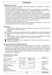
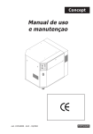
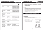
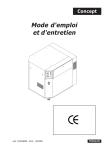
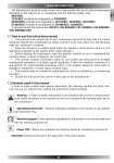
FOREWORD
Use of the Instruction manual
This manual is integral part of this compressor and should be kept for its whole working
life.
Keep this manual in a safe place so not to damage it.
If the compressor is sold to a third party, also give the Instruction Manual to the new Owner.
This manual should be carefully read before starting the compressor up and in case of any
doubt on its operation.
This manual contains important safety information on operation procedures, which should
be complied with, otherwise injuries to people or damages to the machine might occur.
Important use and maintenance instructions are also mentioned in this manual.
Should this manual be lost, please ask for a new copy
Spare parts list is not considered as integral part of this manual, since it is available at
authorized dealers’ offices only.
Symbols
The following symbols are used for especially important information:
Caution
Highlights precautions to be taken to ensure safety of the operator, people in the
compressor working area and the compressor.
Notes
Highlights recommended instructions or precautions to be taken to have an easier
maintenance procedure or to explain most important instructions.
Specialized personnel
Every intervention highlighted by this symbol is exclusively the job of a specialized
technician.
Technical Assistance
Use only genuine spare parts for servicing the compressor.
Non-genuine spare parts might cause injuries to people. For efficient Technical Assistance,
please always state model, type and part number of Your compressor. Those data are
specified both on compressor plate and label on manual cover page.
Product identification
Manufacturer’s data
TYPE = name
CODE = compressor code
SERIAL NO. = serial number
1
Air delivered (l/min) and (cfm)
4
Technical data:
voltage (V/ph/Hz)
absorption (A)
power (HP and kW)
rotations per minute (Rpm).
6
2
3
5
CE mark
year
of manufacture
max. pressure
(bar and PSI)
noise level
dB(A)
7
other
approvals
E/1
ENGLISH
1.GENERAL INFORMATION
This compressor was designed and manufactured to be used only to deliver compressed
air for handicraft and/or industrial applications in full compliance with the safety instructions
provided in the following paragraphs.
Compressor can be equipped with several accessories for blowing, washing and painting
as well as air tools. See the relevant manuals for correct use of accessories and tools.
Carefully read the User’s Manual before servicing the compressor.
Before performing maintenance work, switch off the compressor and cut off power supply
by switching off the wall-mounted switch (if any).
What SHOULD BE DONE:
• Understand how to stop the compressor at once and become familiar with the use of all
controls.• Before any operation the compressor tank should be emptied. Unplug the
compressor so to avoid any
accidental compressor start.
• After any maintenance operation make sure all the disassembled parts are properly
assembled.
• To have a safe operation, make all checks mentioned in chapter “Start-up” before starting
the compressor.
• Keep children and animals away from the working area, so as to avoid any injury
caused by devices
connected to the compressor.
• Carefully read the instructions of any tool you have installed, especially if a spray gun is
used, make sure the shop is well ventilated before you start painting.
• Always start and stop three-phase compressor through the wall switch.
• Should the compressor be working around the clock, the use of soundproof headset is
recommended.
What SHOULD NEVER BE DONE:
• Do not paint indoor or close to naked flames.
• Never touch cylinder head, cooling fins and delivery tube since they become very hot
while working. They are still very hot for some time after stopping the compressor.•
Never place inflammable nylon or cloth objects near or/and on the compressor.
• Never move the compressor when the tank is under pressure.
• Never use the compressor if the power cable is faulty or the connection is not safe.
• Never aim the air jet either at people or animals.•
Never allow anyone to operate
the compressor without giving him/her proper instructions
• Never hit flywheel and fans with metal or blunt objects. Compressor might break or be
seriously damaged.
• Never operate the compressor without an air filter.
• Never tamper with the safety valve or the tank.
• Never use the compressor in potentially explosive premises.
• Never connect the air outlet cock to a tube with a max. capacity which is lower than the
compressor capacity.
Never run the compressor when temperature is under 0°C (operating temperature
range: +5°C / +40°C).
E/2
1.GENERAL INFORMATION
Standard accessories
1
The compressor is supplied with the following accessories:
a) anti-vibrating element or pivoting wheel (50-100-lt tank)
b) 2 wheels + assembly pins (50-100-lt tank)
c) box key (50-100-lt tank)
d) 4 plastic pivoting wheels (20-lt tank)
e) user’s manual (all models)
f) oil dipstick (lubricated models)
Unpacking and Handling
This machine is supplied on a wooden pallet and protected
by a top paper cover.
1. Wear safety gloves and cut straps with scissors and withdraw the paper from the
machine top.
2. Hoist the compressor using a means with a suitable lifting power
3. Fit the wheels and/or the anti-vibrating elements.
Before accepting the delivery, check all machine parts and accessories are included
and for the perfect integrity of the machine. Possible objections will not be accepted
after delivery acceptance.
We recommend the package be kept so that it can be used again in case the compressor
is moved. Keep it for the warranty period at least. If needed, it will be easier and safer to
pack and send it to the service center. After this period, deliver the package to the authorized
organization for its disposal.
Compressor description
2
Compressor main components are
(fig.2):
1. Pressure switch
2. Line cock
3. Safety valve
4. Non-return valve
5. Compressor pump
6.Tank
E/3
ENGLISH
2. INSTALLATION
Placement
Upon installation, make sure that the chosen place is in compliance with all prevailing
national safety standards and meets the following requirements:
• low percentage of dust suspended in air,
• shop must be suitably sized and well ventilated so that room temperature never exceeds
40°C when the compressor is working. If this is not the case, install one or more exhaust
fans to extract hot air. Ideally, the fans should be installed close to the ceiling.
• Leave at least 20 cm between the machine and any object which might obstacle a
proper air flow and therefore reduce ventilation and cooling.
• Lubricated machines: to be never positioned on slopings over 15°C
Power connection
The compressor is delivered to the Customer after being
successfully tested by the Manufacturer. When purchased
is therefore ready for use.
Electrical hook-up is of major importance. Before
performing any operation is very important to make sure
that the voltage mentioned on the compressor label (or on
the label on the cover sheet of this manual) complies with
the mains voltage and the main switch is on OFF/0 ( fig.3)
• Single-phase models
Connect the plug to a proper socket. Call only specialized
personnel, in case of changes to be made for compliance
with the standards of the country in which the compressor
is used.
• Three-phase models
Call a specialized technician for installing a wall switch
equipped with fuses having values not under the values
indicated in the relevant table. Install the switch close to
the machine cable exitand at operator’s reach.
3
I
3
2
20
0
40
5
20
0
6
4
30
10
1
50
0
40
-
+
3
2
4
30
10
1
5
50
6
0
P
0
Power Absorption (A)
HP
V 230
V 400
1,5
5,2
3
2,5
8
4,6
3
8,6
5
3. START-UP
Controls and control instruments
1. Pressure switch (single phase model)
built-in pressure switch (three-phase model)
2. Line cock
3. Safety valve
6. Tank pressure gauge
7. Air outlet pressure gauge
8. Pressure reducing valve
9. ON/OFF switch
Operation
The compressor is operated by the pressure switch/builtin pressure switch and stops about a minute later after
reaching the allowed max. pressure. During this period
the compressor will run without compressing any air so
that the compressor-box assembly can be cooled down,
E/4
4
9
6
7
8
8
2
7
9
6
3
1
3. START-UP
whereas the solenoid valve will bleed the air off the final manifold and head, thus favoring
next compressor start.
A short air blow of some seconds when the compressor stops is therefore a sign of proper
compressor operation (this blow cannot be heard during regular use with door closed). As
soon as pressure reaches the min. allowed value, the compressor will automatically start.
Operating pressure adjustment
Check for optimal operating pressure value of the accessory to be used with the relevant
manual.
Adjust the air pressure at the outlet according to the required value through the pressure
reducing valve 8 (fig.4). Turn the knob clockwise to increase pressure and anti-clockwise to
decrease. The set value is indicated by the pressure gauge 7 (fig.4).It is recommended the
pressure value be zeroed after use so that the pressure reducing valve will not be subject
to earlier wear.
First start-up
Once the compressor has been carefully positioned and connected, it is ready for start-up.
It is recommended this operation - operational test - be performed by a specialized
technician.
Before continuing, make sure that
• mains voltage is the same as voltage mentioned in the machine plate;
• all connections have suitable cross-section cable (see table) and that cables are neither
damaged nor have bare wires;
• wall switch is equipped with suitable fuses (see table);
• oil level is over the minimum level.
After checking the above, proceed as follows:
• Power the wall switch on (Three-phase Pulsar).
Plug the machine (Single-phase Pulsar);
• Start the compressor powering on the control panel switch (20-lt tank) or through the
pressure switch/built-in pressure switch (50-100-lt tank) (fig. 3);
• Allow the motor to run for at least 5 minutes with the air valve open. After that time, close the
valve and make sure the compressor is loading the tank and stops after reaching the max.
pressure value indicated by the pressure gauge 6 (fig, 4).
Never unplug the compressor to stop it but always position either the switch on the pressure
switch body or the wall switch to Off. In this way the compressed air in the head will be bled,
thus favoring next compressor start.
Safety devices
Safety valve on the pressure switch/built-in pressure
switch: bleeds the air off once the max. safety value has
been reached.
Motor thermal cutout (fig.5): in case of motor overheating
due to some troubles, this device will trip, thus cutting the
machine out and avoiding any motor damage.
Allow some minutes (about 5) before manually resetting
the thermal cutout so that the motor can restart.
If the switch trips again on motor restarting, power the
machine off. Unplug the compressor and call an authorized
service center.
E/5
5
ENGLISH
4. MAINTENANCE
General information
The compressor should be serviced at regular intervals
for a proper operation. Switch the compressor off and
bleed all air off the tank before any servicing.
6
After first 100 working hours
• Check for proper tightening of all screws, in particular
the head screw.
• Check for the proper tightening of all pipe fittings.
• Check that no dust is inside the box and see whether
the installation place is really the right one. Compressor
should not be dusty.
• Change oil (fully) using one of the safety oil types
indicated on page 7.
close
open
7
Condensate drain (weekly)
Condensate is drained through the drain valve on the box
front side (20-lt tank model) or under the tank (50-100-lt
tank model):Just position a proper container for condensate collection and open the valve by turning counterclockwise.
Close the valve when only air starts coming out (fig.6).
If your compressor is of the lubricated type, condensate
should never be drained into the sewage system since it
may be polluant.
Clean air suction filter (monthly)
• 20-lt tank models:Remove the upper cover from the top.
• 50-100-lt tank models:Remove the cover from the top
or open the box door using the proper key.
Filter types:
A) MK 150-MK282-VKM300 (fig.7-A)These compressor
assemblies are equipped with one or two suction filters
fitted beside the compressor head. To open the filter,
unscrew the middle screw.
B) VKM402 (fig.7-B)These compressor assemblies are
equipped with one or two suction filters fitted beside the
compressor head. To pull out the filtering element just open
the bottom door.Wash the sponge element with water and
soap. Rinse and dry properly before re-fitting. Close the
filter.
Never run the compressor if suction filter is not fitted.
Should foreign bodies or dust go into the filter, its inner
parts might seriously damage.
NOTE: CHANGE THE FILTERING ELEMENT AFTER TWO
OIL CHANGES.
A
B
8
B
A
C
MAX
MIN
Check and top-up oil (monthly)
Remove the cover as indicated in the above paragraph.Withdraw the oil dipstick C and
make sure the oil level is within the min. and max. level. Top up through suitable filler B (fig.
8), if necessary.
Change oil (every six months)
Withdraw the oil dipstick C, unscrew the plug A and deliver the exhausted oil into a container
E/6
4.MAINTENANCE
with the help of the suitable detachable sheet fitted between the compressor unit and the
tank connection sheet. Screw the plug A and continue as indicated above.
Change the oil or top up always when the compressor is still warm.
Never mix different types of oil together.
Poor oils are not recommended,since they may have unsuitable lubrication properties.
Recommended oils
SHELL Rimula D Extra 15W-40
AGIP Dicrea 100
BP Energol CS100
ESSO Exxc Olub H150
MOBIL Rarus 427
FUCHX Renolin 104L VG100
API CM-8X
CASTROL Aircol PD100
IP Calatia Oil ISO 100
TOTAL Dacnis P100
OIL SHOULD ALWAYS BE DISPOSED OF IN COMPLIANCE WITH CURRENT LAWS.
CALL AUTHORIZED BODY FOR ITS DISPOSAL.
Later maintenance
• Every 6 months
It is recommended to clean all compressor finned parts for
an efficient cooling system and therefore a higher machine
performance.
• Each year
Change the filtering element.
• Each two years
1. Check and clean delivery and suction valves.
2. Check for proper conditions of the non-return valve and
change the gasket A, if necessary (fig. 9).
In these cases, it is recommended all seals be changed.
E/7
9
A
ENGLISH
TROUBLESHOOTING
Problem
Cause
Remedy
Air leaking off pressure
switch valve when the
compressor is stopped.
Check valve leaking.
Bleed air off the tank, remove the check
valve cap and clean valve seat and
sealing element. Replace the sealing
element, if necessary.
Air leaking off pressure
switch valve for a long time
when the compressor is
running.
Loadless start valve broken.
Replace the valve.
The compressor stops and
cannot be restarted.
Motor overheating, Thermal
cutout tripped.
Allow some minutes (about 5) before
manually resetting the thermal cutout.
Should the compressor stop once
again, call a specialized technician.
Winding burnt.
Call a specialized technician.
The compressor stops once Pressure switch defective or Call a specialized technician.
broken.
max. pressure has been
reached and the safety valve
starts working.
The compressor does not
charge and causes
overheating.
Heat gasket or valve broken.
Stop the compressor with no delay and
call a specialized technician.
The compressor is too noisy
and rattles.
Bearings seizure.
Stop the compressor with no delay and
call a specialized technician.
E/8