Download R&S®ESCI7 EMI Test Receiver Compliance measure
Transcript
Product Brochure | 01.00
Test & Measurement
R&S®ESCI7
EMI Test Receiver
Compliance measurements in line with
commercial standards
up to 7 GHz
R&S®ESCI7
EMI Test Receiver
At a glance
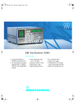
The R&S®ESCI7 EMI test receiver is a standard-compliant measuring receiver for EMC certification measurements in line with commercial standards in the
frequency range from 9 kHz to 7 GHz. The receiver
conforms to the latest version of the CISPR 16-1-1
basic standard. At the same time, it functions as a
full-featured and powerful spectrum analyzer for lab
applications.
In line with the latest version of commercial EMC stan‑
dards, the R&S®ESCI7 EMI test receiver measures and
analyzes electromagnetic disturbances produced by
devices, modules and components in the frequency range
from 9 kHz to 7 GHz. It fulfills the requirements of the cur‑
rent CISPR 16‑1‑1 basic standard, including the average
detector with meter time constant (CISPR-average) and
the RMS-average detector.
2
Time-saving, automatic test routines considerably reduce
the required effort. Effective analysis capabilities, clear pre‑
sentation of results and straightforward, intuitive operation
provide support to users in product development or type
approval testing, for example.
In addition, the R&S®ESCI7 can be used as a high-quality
spectrum analyzer. Diverse test functions for general mea‑
surements encountered in the lab extend the instrument's
range of applications beyond pure disturbance measure‑
ments to provide additional benefit.
Key facts
JJ Combination
of standard-compliant EMI test receiver and
high-quality spectrum analyzer
JJ Integrated preselection with selectable 20 dB preamplifier
JJ Frequency range from 9 kHz to 7 GHz; usable for all
commercial EMC standards
JJ Effective analysis of the disturbance spectrum through
simultaneous graphical presentation of the distur‑
bance level and emission spectrum around the receive
frequency
JJ Time-domain analysis for evaluation of timing behavior of
disturbances (e.g. click-rate analysis)
JJ Automatic consideration of coupling devices such as line
impedance stabilization networks, probes, cables and
antennas using transducer factors and sets
R&S®ESCI7
EMI Test Receiver
Benefits and
key features
Standard-compliant disturbance measurements
JJ Characteristics
Total measurement uncertainty 1.0 dB (< 3 GHz) and
1.5 dB (3 GHz to 7 GHz)
1 dB compression +5 dBm
Displayed average noise level with preamplifier
typ. –153 dBm (10 Hz)
Twelve preselection filters up to 7 GHz
Resolution bandwidths in line with CISPR 16-1-1
Detectors: max./min. peak, quasi-peak, average,
CISPR-average, RMS, RMS-average
▷▷ page 4
WW
WW
WW
WW
Intuitive operation and powerful EMI analysis
functions for fast, accurate results
JJ User-friendly operation as with all EMI test r eceivers from
Rohde & Schwarz
JJ SCAN settings in tabular format
JJ Simultaneous measurement of multiple traces for parallel
evaluation
JJ Fast, reliable measurements using automatic and
interactive test routines
JJ EMI test receiver and spectrum analyzer in a single box –
display in MIXED MODE operation
JJ Continuous bargraph display and marker functions for
precise measurements
JJ Time-domain analysis – oscilloscope function in receiver
mode
JJ Automatic disturbance voltage measurements using
remote-controllable line impedance stabilization networks
(LISN) from Rohde & Schwarz
JJ Predefined transducer factors
JJ Library of limit lines for commercial standards
▷▷ page 6
WW
WW
Integrates perfectly into the work environment
expansion or upgrading by means of options
Scalar network analysis
RF level measurement
Modulation measurement
JJ Extensive documentation and networking capabilities
like a PC
JJ Computer-controlled measurement of disturbancesand
automated EMI test routines using the R&S®ES‑SCAN
and R&S®EMC32 EMI measurement software
JJ Always up-to-date with free firmware updates
▷▷ page 12
JJ Easy
WW
WW
Spectrum analysis for lab applications
JJ High-quality spectrum analyzer included
JJ Extensive measurement functions and evaluation
capabilities for general lab applications
▷▷ page 5
WW
Rugged and environmentally friendly, suitable even
for field applications
JJ Housing option for outdoor use
Shock-absorbing corners, carrying handle, carrying bag
JJ AC-independent operation using DC power supply and
battery pack (option)
JJ Flash disk option for expanded environmental
specifications
JJ Environmentally friendly design
Small number of materials
Easy identification of materials through labeling
Recyclable housing
▷▷ page 13
WW
WW
WW
WW
Rohde & Schwarz R&S®ESCI7 EMI Test Receiver 3
Standard-compliant
disturbance
measurements
Characteristics
Full-compliance EMI test receivers are always used when
certifications must be performed in line with relevant stan‑
dards. CISPR 16-compliant measurements are extremely
demanding for the test equipment since the equipment
must be capable of handling a wide variety of disturbance
signals. This includes pulsed and sinusoidal signals as well
as modulated and intermittent signals, all of which must
be correctly weighted.
The R&S®ESCI7 EMI test receiver is designed for such ap‑
plications. With its integrated preselection with twelve
fixed and tunable filters, a 20 dB preamplifier and a highly
linear frontend, the instrument meets the requirements
of commercial standards such as CISPR, EN, ETS, ANSI,
FCC and VCCI. Other impressive characteristics include
1.0 dB total measurement uncertainty (up to 3 GHz) and a
1 dB compression point of +5 dBm. With its low displayed
average noise level (typ. –153 dBm for 10 Hz bandwidth
and preamplifier switched on), the R&S®ESCI7 can also be
used to precisely measure very low-amplitude signals with
a good signal-to-noise ratio.
The available weighting detectors including average with
meter time constant (CISPR-average) and RMS‑average
as well as the EMC resolution bandwidths (200 Hz, 9 kHz,
120 kHz as 6 dB bandwidths, 1 MHz as impulse band‑
width) fulfill the current version of the CISPR 16-1-1 basic
standard.
Measurement of radiated disturbances
in line with the product s tandard
CISPR 22:2005 Amend. 1: 2005/
EN 55022: 2006 Amend. 1: 2007 for information
technology equipment (ITE) in the range
from 1 GHz to 6 GHz using the R&S®ESCI7
EMI test receiver and the R&S®HF907 doubleridged waveguide horn antenna.
4
Spectrum analysis
for lab applications
High-quality spectrum analyzer included
Like all modern EMI test receivers from Rohde & Schwarz,
the R&S®ESCI7 is based on a powerful spectrum ana‑
lyzer platform. This relationship provides comprehensive
measurement capabilities from the standard repertoire of
a high-quality spectrum analyzer including disturbance
measurements required in development (with preselec‑
tion/preamplifier activated when required) and also many
customized analyzer functions that help to significantly
expand the range of possible applicationsbeyond EMC
measurements.
Extensive measurement functions and evaluation
capabilities for general lab applications
For many of the typical lab measurements, the R&S®ESCI7
provides fast test routines such as the following:
JJ Determination of the third order intercept point (TOI)
JJ Occupied bandwidth (OBW)
JJ Adjacent channel power (ACP) measurement
JJ Statistics functions (APD, CCDF)
JJ Burst power, peak, average and RMS display
JJ Phase noise
JJ Bandwidth marker
All IF bandwidths can be selected in both receiver and
spectrum analyzer mode:
JJ EMI bandwidths of 200 Hz, 9 kHz, 120 kHz and 1 MHz in
line with CISPR 16-1-1
JJ Resolution bandwidths (–3 dB) from 10 Hz to 3 MHz
(1/3/10 steps)
JJ 44 digital channel filters from 100 Hz to 5 MHz
Overview of preprogrammed ACP
standards for adjacent channel
power ratio (ACPR) measurement,
which is a power measurement
specified in many mobile radio
standards.
Statistical signal analysis using the complementary
cumulative distribution function (CCDF) provides the precise
CCDF trace, average and peak power as well as the crest
factor over one million measured values.
Rohde & Schwarz R&S®ESCI7 EMI Test Receiver 5
Intuitive operation
and powerful EMI
analysis functions
User-friendly operation as with all EMI test receivers
from Rohde & Schwarz
Operation of the R&S®ESCI7 is tailored to applications
in EMC labs. The receiver provides great ease of use
and a large number of additional functions for analyzing
disturbances.
All important parameters are easy to read off on the
8.4"/21 cm TFT color display. The current parameter set‑
tings are always clear at a glance. Vertical and horizontal
softkey bars help the user to perform complex measure‑
ment tasks. Dedicated hardkeys with unit keys are provid‑
ed for entering values such as frequency and amplitude.
SCAN settings in tabular format
In receiver mode, the SCAN table provides the basis for
disturbance measurements in the frequency domain. The
parameters are presented in a clear tabular format and can
be individually adapted to the measurement and the de‑
vice under test. The SCAN table can be saved and printed,
allowing the user to easily keep track of how the measure‑
ment results were produced.
Menu for selecting the main receiver settings (receiver
mode). In the upper window, the SPLIT SCREEN display
shows the continuously updated level values for the select‑
ed detectors (max. three simultaneously) and the set mea‑
surement frequency. The lower window shows the mea‑
sured emission spectrum using the SCAN table settings. Up
to three traces with a maximum of 1 million measurement
points each can be simultaneously active.
6
Simultaneous measurement of multiple traces for
parallel evaluation
The R&S®ESCI7 can weight up to three measurement
traces using different detectors and present them in a
diagram.
The benefits are as follows:
JJ Saving time through simultaneous measurement with
different detectors
JJ Clear identification of measurement traces in the diagram
JJ Quick overview of results through assignment of limit
lines
All measurement data (up to 1 million measurement
points per trace) is saved in the internal memory and can
be exported in ASCII format. The displayed frequency
range is traced back to "real" measured values even when
the display is highly zoomed (e.g. during subsequent de‑
tailed analysis work). Due to the large number of measure‑
ment points, the R&S®ESCI7 in receiver mode delivers
high frequency resolution and high accuracy for the distur‑
bance frequency even with scans covering wide frequency
ranges. This is a major benefit compared to the spectrum
analyzer which has a significantly lower number of sweep
points.
In receiver mode, the R&S®ESCI7 is tuned in fixed f requency
steps in line with the settings in the SCAN t able. The SCAN
table can be programmed for a maximum of ten frequency
subranges with independent parameter s ettings (e.g. start/
stop frequency, step size, measurement time, r esolution
bandwidth, input attenuation). Each time a scan is launched
by entering a START and STOP f requency, the parameters
that are preset in the SCAN table are loaded a
utomatically.
This always ensures reproducible and s tandard-compliant
measurements.
Menu for selecting the weighting detectors; the values for
a maximum of three different detectors are simultaneously
displayed numerically and as an analog bargraph.
Rohde & Schwarz R&S®ESCI7 EMI Test Receiver 7
Fast, reliable measurements using automatic and
interactive test routines
Disturbance measurements become faster and simpler by
combining a fast preview measurement with peak (and
average) detector and a final measurement exclusively on
the automatically determined critical frequencies ("data
reduction").
The R&S®ESCI7 provides common limits from commercial
product standards and compares them with the result of
the preview measurement. It then determines the critical
disturbance frequencies and lists them in a table (peak list)
which can be manually edited prior to performing the final
measurement with a standard-compliant measurement
time and CISPR detector(s). This is a way of interactively
adding additional frequencies or deleting existing ones.
For disturbance signals that drift in frequency, the
R&S®ESCI7 provides a specially modified automatic test
sequence called THRESHOLD SCAN. The receiver inter‑
rupts the preview measurement as soon as a selectable
limit value is exceeded and immediately performs a final
measurement using standard-compliant receiver settings.
The receiver then continues the preview measurement
with the next frequency step. As soon as the limit value
is e
xceeded again, the next final measurement is per‑
formed. This technique has a significant benefit: The final
measurement, e.g. with quasi-peak weighting, immediate‑
ly takes place when a critical disturbance level is detected
during the preview measurement. This eliminates the risk
of measurement errors due to frequency drift of the distur‑
bance signals. The receiver saves the final measurement
results in a separate table (peak list) for subsequent evalu‑
ation and documentation.
All parameters for the final measurement at the critical frequencies can be
configured in a submenu. The final measurement frequencies are deter‑
mined either for the absolute peaks or as subrange maxima. The relative
magnitude of a disturbance level, its offset from the limit value (margin)
and the maximum number (1 to 500) can all be set. The final measurement
is performed either fully automatically or interactively.
An automatic test sequence consists of preview measurement, data
reduction and final measurement. The maximum disturbances and their
offset from the set limit value are automatically determined. This speeds
up the measurement and simplifies data evaluation. The final measure‑
ment frequencies determined in this manner are saved by the R&S®ESCI7
in a separate, editable table (PEAK LIST) for subsequent disturbance
analysisand for documentation purposes.
8
EMI test receiver and spectrum analyzer in a
single box – display in MIXED MODE operation
The R&S®ESCI7 combines an EMI test receiver and a
spectrum analyzer in a single instrument. The benefits
of the analyzer mode are mostly related to disturbance
measurements performed in product development with
fast sweeps for overview and preview measurements and
evaluation using marker functions. The user can choose
between standard-compliant CISPR bandwidths (includ‑
ing 1 MHz impulse bandwidth) and 3 dB resolution band‑
widths (10 Hz to 3 MHz). For this purpose, preselection
filters and a preamplifier can be activated in the analyzer
mode. This is a significant a
dvantage compared to a
"pure" broadband spectrum analyzer. Operation as a clas‑
sic EMI test receiver, however, provides sophisticated data
reduction and standard-compliant final measurements.
In MIXED MODE, the R&S®ESCI7 offers both operating
modes in a split-screen presentation.
A large number of the operating parameters can be either
coupled or decoupled for the two operating modes. Set‑
ting the same center frequency for both screens, for ex‑
ample, automatically produces the same display as in IF
analysis. The object is to obtain a spectral display of the
RF input signal around the receive frequency within a se‑
lectable range. Ideally, this display is output in parallel to
a numeric measurement at the current receive frequency.
Since the center frequency of the displayed spectrum al‑
ways corresponds to this receive frequency, the measuring
receiver can be tuned very accurately and quickly to the
signal of interest.
In addition, the user obtains an exact overview of
spectrum occupancy around the measurement channel
and – if the IF bandwidth is sufficiently large – informa‑
tion about the spectral distribution of a modulated signal
in the measurement channel. Any signals received can be
quickly classified as disturbance signals or wanted signals,
including CW signals present in the form of unmodulated
carriers or impulsive disturbances that travel across the
screen in the form of narrow lines.
The benefits of this mixed-mode display are as follows:
accurate tuning of the EMI test receiver's frequency
to the local disturbance maximum
JJ Faster and simpler identification of signals
JJ Ideal tool for investigating the spectrum that surrounds
disturbance signals
JJ More
Mixed-mode display: bargraph measurement and spectrum. The standardcompliant measurement in the bargraph display and the fast sweep are
shown simultaneously.
Alternative mixed-mode display: receiver scan and spectrum with
MARKER TRACK function. The saved frequency scan and fast sweeps
around the current marker frequency are displayed simultaneously.
Rohde & Schwarz R&S®ESCI7 EMI Test Receiver 9
Continuous bargraph display and marker functions
for precise measurements
In parallel to the numeric display after weighting with up
to three different detectors, the R&S®ESCI7 presents the
measured values using a bargraph display. This allows the
user to rapidly recognize the influence of changes on the
device under test. Even in case of changes of the receive
frequency, the bargraph will track the signal without inter‑
ruption, making it easier to search for the highest signal
level. The receiver also records the highest level (MAX
HOLD) and the associated frequency, which provides use‑
ful support to the user when searching for the highest‑am‑
plitude disturbance with fluctuating or drifting signals. At
a keystroke (ADD TO PEAK LIST), the R&S®ESCI7 transfers
the measured frequency directly to a separate frequency
list and saves it for subsequent final measurements.
The R&S®ESCI7 supports the evaluation of the displayed
measurement trace(s) by means of marker functions, e.g.
for fast and reliable determination of frequencies and rela‑
tive levels. The CENTER = MARKER FREQUENCY and
MARKER TRACK functions are also useful. The first func‑
tion sets the receiver frequency at a keystroke such that
the signal to be measured is exactly at the center frequen‑
cy. When MARKER TRACK is activated, the receive fre‑
quency automatically follows the marker on the trace. This
allows the user to tune the R&S®ESCI7 quickly and pre‑
cisely to the individual disturbance maxima in sequence,
e.g. with a simple keystroke (NEXT PEAK).
Time-domain analysis – oscilloscope function in
receiver mode
The duration of the preview measurement is significantly
influenced by the measurement time per frequency step.
To reliably measure an impulsive disturbance, for example,
the dwell time per frequency step must be set at least as
large as the reciprocal of its pulse repetition frequency
(PRF). An impulsive disturbance with a PRF of 100 Hz, for
example, requires a measurement time of at least 10 ms.
The R&S®ESCI7 features a very useful tool for optimiz‑
ing this dwell time: time-domain analysis. The user can
perform a scan in the time domain on the set receive fre‑
quency (similar to the zero span provided by spectrum
analyzers) to assess the timing behavior of disturbances
– comparable to using an oscilloscope. In this manner, the
user can determine the pulse rate of a broadband intermit‑
tent disturbance so as to be able to set the optimum mea‑
surement time, i.e. as short as possible but as long as nec‑
essary. The user can also determine whether and to what
extent a narrowband disturbance signal is fluctuating, and
whether it is amplitude-modulated or pulsed.
Click-rate analysis is a special application: Thermostatic
or program-controlled electrical appliances such as wash‑
ing machines and air conditioners generate discontinu‑
ous disturbances. Due to the aperiodic timing, CISPR 14
and EN 55014 stipulate higher disturbance voltage limits
for such click-type disturbances than for continuous
The R&S®ESCI7 allows precise evaluation of all
measurement traces using marker and zoom
functions. The MARKER TRACK and TUNE TO
MARKER functions link the frequency tuning
and numeric level measurement to the marker
position on the trace. Final measurements at the
critical frequencies determined in this way can
be performed more quickly and easily.
10
isturbances. If the user wants to apply these limits, it is
d
necessary to measure the length in time of the clicks, their
repetition rate (click rate) and their levels in order to then
use these values to determine the applicable limits.
Clicks are normally measured using special click-rate
analyzers. The time-domain analysis capability integrated
into the R&S®ESCI7 can consecutively determine the pulse
height and duration at each of the frequencies stipulated
in the standard and thus reproduce the functionality of
an expensive click-rate analyzer. The R&S®ESCI7 fulfills
CISPR 16‑1‑1 in terms of the accuracy of the pulse dura‑
tion measurement for pulse durations equal to 10 ms.
With a capacity of 1.44 million measured values in the
time domain, it has sufficient memory to continuously
record the peak value and quasi-peak value for at least two
hours. A PC-based software is available for evaluation in
line with CISPR 14‑1/EN 55014‑1.
Predefined transducer factors
For disturbance measurements using test antennas for
example, the R&S®ESCI7 includes a selection of typical an‑
tenna factors (transducers). Users can also create and save
their own correction tables for antennas, cable losses,
preamplifiers, etc. The R&S®ESCI7 automatically takes into
account all activated correction factors in the measured
values and selects the appropriate unit.
Library of limit lines for commercial standards
In addition to the transducer factors, the R&S®ESCI7 also
includes a selection of important limits (LIMIT LINES) in
line with commercial standards. Users can enter and save
changes to the limit lines and create new limit lines using
a tabular format.
Automatic disturbance voltage measurements u
sing
remote-controllable line impedance stabilization
networks (LISN) from Rohde & Schwarz
Disturbance voltage measurements on power lines are
made using line impedance stabilization networks. For this
application, Rohde & Schwarz offers the R&S®ENV216 twoline V-network and the R&S®ESH2-Z5 and R&S®ENV4200
four-line V-networks. The R&S®ESCI7 automatically switch‑
es the different phases of this LISN using an optional con‑
trol cable. This ensures that the largest d
isturbance is actu‑
ally measured.
R&S®ENV216 two-line V-network (LISN).
Rohde & Schwarz R&S®ESCI7 EMI Test Receiver 11
Integrates perfectly
into the work
environment
Easy expansion or upgrading by means of options
Scalar network analysis
The optional R&S®FSP-B9 (internal tracking generator,
9 kHz to 3 GHz) and R&S®FSP-B10 (external generator con‑
trol) expand the R&S®ESCI7 to operate as a scalar network
analyzer. The selective measurement technique allows
gain, frequency response, insertion loss and return loss to
be measured with a wide dynamic range and without be‑
ing influenced by generator harmonics or spurious.
The R&S®FSP-B9 internal tracking generator covers the
frequency range from 9 kHz to 3 GHz. A frequency offset
of ±150 MHz can be set for testing frequency‑converting
modules. The tracking generator can be broadband-modu‑
lated using an external I/Q baseband signal.
The R&S®FSP-B10 option uses commercially available RF
signal generators as an external tracking source. They are
controlled via the IEC/IEEE bus or a TTL bus. The range
of functions corresponds to that of the internal tracking
generator.
RF level measurement
The R&S®FSP-B6 option provides a selectable RF level
trigger for measurements on pulsed RF signals used in
TDMA communications systems.
Modulation measurement
Using the R&S®FS-K7 measurement demodulator option,
the R&S®ESCI7 can measure synthesizer settling or fre‑
quency deviation, for example. This option also enables
Fourier analysis of the RF signal or the demodulated AF
signal.
Display choices:
JJ Frequency, amplitude or phase modulation
versus time
JJ Carrier power versus time
JJ RF spectrum (FFT)
JJ AF spectrum (FFT of demodulated signal) with measured
SINAD and THD values
12
Extensive documentation and networking
capabilities like a PC
The R&S®FSP-B16 LAN interface option configures the
R&S®ESCI7 like a network workstation:
JJ File logging on network drives
JJ Network printer
JJ Remote desktop function
JJ Remote control via LAN
The Windows XP Embedded operating system and the
diverse data interfaces allow smooth integration of the
instrument into a PC environment.
For further processing, the R&S®ESCI7 saves the mea‑
sured values as ASCII files to document the trace data as
well as the most important instrument settings.
Documentation of measurement results, graphics, scan
tables and transducer/limit value tables can be conve‑
niently handled by connecting a printer to one of the USB
interfaces on the front or rear panel. This ensures the com‑
plete, reproducible evaluation of tests also as a hard copy.
For software integration, instrument drivers are available
free of charge for LabView, LabWindows/CVI and VXI
Plug & Play.
Computer-controlled measurement of disturbances and automated EMI test routines using
R&S®ES‑SCAN and R&S®EMC32
The R&S®ES-SCAN and the R&S®EMC32 EMI measure‑
ment software products complement the R&S®ESCI7.
R&S®ES‑SCAN is a cost-effective and user-friendly
Windows software that was specially created for distur‑
bance measurements during development. R&S®EMC32
is a modular test software that supports manual as well
as partially or fully automated EMC measurements in line
with commercial and military standards. It ensures reliable
recording, evaluation, documentation and traceability of
measurement results.
Always up-to-date with free firmware updates
The R&S®ESCI7 firmware is easy to update using a USB
memory stick or the LAN interface. Firmware updates
are available free of charge from the Rohde & Schwarz
website.
Rugged and
environmentally
friendly, suitable
even for field
applications
Housing option for outdoor use
The R&S®ESCI7 is also available in a rugged housing with
shock-absorbing corners and a carrying handle for outdoor
use (R&S®FSP-B1 option).
AC-independent operation using DC power supply
and b
attery pack (option)
The R&S®FSP-B30 DC power supply option allows
operation from DC sources between 12 V and 28 V.
Using the R&S®FSP-B31 battery pack, the receiver can
record measurement sequences continuously for several
hours during applications in the field. The time can be ex‑
tended as required using additional battery packs.
Flash disk option for expanded environmental
specifications
A hard drive is normally used to save data in the
R&S®ESCI7. For applications with above-average fluctua‑
tions of the operating temperature (0 °C to +55 °C) or when
the instrument is subjected to strong shocks and vibrations
(e.g. in a vehicle), the user can order an internal flash disk
(R&S®ESCI-B20 option) instead of the internal hard disk.
Rear panel of the R&S®ESCI7.
Rohde & Schwarz R&S®ESCI7 EMI Test Receiver 13
Specifications in brief
Base unit
Frequency range
9 kHz to 7 GHz
Frequency resolution
Frequency accuracy
0.01 Hz
standard
1 × 10⁻⁶
with R&S®FSP-B4 (OCXO) option
1 × 10⁻⁷
External reference frequency
Measurement time
Resolution bandwidth
10 MHz
receiver mode/scan (per frequency step)
selectable from 33 µs to 100 s
analyzer mode/sweep time
selectable from 2.5 ms to 16000 s,
zero span from 1 μs to 16000 s
10 Hz to 3 MHz in steps of 1/3/10
analyzer mode (–3 dB)
receiver mode (EMI)
Video bandwidth
analyzer mode
200 Hz, 9 kHz, 120 kHz (–6 dB),
1 MHz (impulse bandwidth)
1 Hz to 10 MHz in steps of 1/3/10
Preselection
can be turned off in analyzer mode
12 fixed/continuously tunable filters
Preamplifier
can be switched on/off
20 dB gain
Max. RF level (CW)
input attenuation ≥ 10 dB
30 dBm (= 1 W)
Max. pulse energy
input attenuation ≥ 10 dB, 10 µs
1 mWs
Max. pulse voltage
input attenuation ≥ 10 dB, 10 µs
150 V
Third-order intercept (IP3)
without preselection/preamplifier,
from 200 MHz to 3 GHz
with preselection/without preamplifier,
from 200 MHz to 3 GHz
f > 200 MHz, input attenuation 0 dB,
without preselection/preamplifier
95 % confidence level
> 7 dBm, typ. 10 dBm
Level
1 dB compression
Total measurement uncertainty
> 2 dBm, typ. 5 dBm
5 dBm, nominal
< 3 GHz
without preselection/preamplifier
0.5 dB
with preselection/preamplifier
1.0 dB
3 GHz to 7 GHz
Displayed average noise level (DANL)
without preselection/preamplifier
1.5 dB
with preselection/preamplifier
1.5 dB
receiver mode, nominal,
input attenuation 0 dB, termination 50 Ω
without preamplifier, 1 MHz, BW = 9 kHz
without preamplifier, 30 MHz to 1 GHz,
BW = 120 kHz
with preamplifier, 1 MHz, BW = 9 kHz
Detectors
with preamplifier, 30 MHz to 1 GHz,
BW = 120 kHz
receiver mode
Number of measurement points
analyzer mode
receiver mode
< –4 dBµV
< 6 dBµV
< –14 dBµV
< –4 dBµV
max./min. peak, quasi-peak, RMS, average, aver‑
age with meter time constant (CISPR-average),
RMS‑average (CISPR-RMS)
125 to 8001 (default 501)
max. 1 million (frequency domain)
max. 1.44 million (time domain)
The data sheet with complete technical specifications is available at PD 0758.1558.22 and www.rohde-schwarz.com.
14
Ordering information
Designation
Type
Order No.
R&S®ESCI7
1166.5950.07
Base unit
EMI Test Receiver, 9 kHz to 7 GHz
Accessories supplied
Power cable, Tuchel adapter for probe connector, operating manual, service manual
Options
Rugged Case, with carrying handle
R&S®FSP-B1
1129.7998.02
OCXO Reference Frequency
R&S®FSP-B4
1129.6740.02
TV Trigger/RF Power Trigger
R&S®FSP-B6
1129.8594.02
Tracking Generator, I/Q Modulator
R&S®FSP-B9
1129.6991.02
External Generator Control
R&S®FSP-B10
1129.7246.03
LAN Interface 100BaseT
R&S®FSP-B16
1129.8042.03
Expanded Environmental Specifications (flash disk)
R&S®ESCI-B20
1155.1606.14
DC Power Supply 1)
R&S®FSP-B30
1155.1158.02
Battery Pack, with charging unit R&S®FSP-B31
1155.1258.02
Spare Battery Pack (NiMH) 3)
R&S®FSP-B32
1155.1506.02
Noise Measurement Software
R&S®FS-K3
1057.3028.02
FM Measurement Demodulator
R&S®FS-K7
1141.1796.02
2)
Recommended extras
19" Rack Adapter (not with R&S®FSP-B1)
R&S®ZZA478
1096.3248.00
Carrying Case, gray
R&S®ZZT473
1109.5048.00
Pulse Limiter, 0 Hz to 30 MHz
R&S®ESH3-Z2
0357.8810.54
Control Cable for R&S®ESH2-Z5 V-network (length 2 m)
R&S®EZ-13
1026.5293.02
Control Cable for R&S®ESH3-Z5 V-network (length 2 m)
R&S®EZ-14
1026.5341.02
Control Cable for R&S®ENV216, R&S®ENV4200
V-network (length 3 m)
IEC/IEEE Bus Cable, length 1 m
R&S®EZ-21
1107.2087.03
R&S®PCK
0292.2013.10
IEC/IEEE Bus Cable, length 2 m
R&S®PCK
0292.2013.20
R&S®ES-SCAN
1308.9270.02
EMC measurement software
EMI Precompliance Software for R&S®ESPI, R&S®ESCI, R&S®ESL EMI test
receivers and R&S®FSP, R&S®FSL analyzers;
VISA software interface from National Instruments required
EMI Measurement Software; basic version for commercial and military
standards; with hardlock copy protection
EMI Auto Test Option for R&S®EMC32-EB
R&S®EMC32-EB
1300.7010.02
R&S®EMC32-K10
1117.6840.02
Sequencer for EMC measurements
R&S®EMC32-K11
1117.6862.02
Service options
One-Year Repair Service following the warranty period
R&S®RO2ESCI7
1166.5950.S26
Two-Year Repair Service following the warranty period
R&S®RO3ESCI7
1166.5950.S22
Four-Year Repair Service following the warranty period
R&S®RO5ESCI7
1166.5950.S24
Two-Year Calibration Service
R&S®CO2ESCI7
1166.5950.S25
Three-Year Calibration Service
R&S®CO3ESCI7
1166.5950.S21
Five-Year Calibration Service
R&S®CO5ESCI7
1166.5950.S23
Documentation of Calibration Values of the R&S®ESCI7
R&S®DCV-2
0240.2193.09
R&S®ESCI7 DKD (ISO 17025) Calibration incl. ISO 9000 calibration
R&S®ESCI7DKD
1161.2646.07
R&S®FSP-B1 option required.
R&S®FSP-B1 and R&S®FSP-B30 options required.
3)
R&S®FSP-B31 option required.
1)
2)
Rohde & Schwarz R&S®ESCI7 EMI Test Receiver 15
Service you can rely on
J Worldwide
J Local
and personalized
and flexible
J Uncompromising quality
J Long-term dependability
J Customized
About Rohde & Schwarz
Rohde & Schwarz is an independent group of companies
specializing in electronics. It is a leading supplier of solu‑
tions in the fields of test and measurement, broadcasting,
radiomonitoring and radiolocation, as well as secure com‑
munications. Established 75 years ago, Rohde & Schwarz
has a global presence and a dedicated service network in
over 70 countries. Company headquarters are in Munich,
Germany.
Environmental commitment
JJ Energy-efficient products
JJ Continuous improvement in environmental sustainability
JJ ISO 14001-certified environmental management system
Certified Quality System
ISO 9001
Rohde & Schwarz GmbH & Co. KG
www.rohde-schwarz.com
Regional contact
Africa, Middle East
+49 1805 12 42 42* or +49 89 4129 137 74
[email protected]
JJ North America
1 888 TEST RSA (1 888 837 87 72)
[email protected]
JJ Latin America
+1 410 910 79 88
[email protected]
JJ Asia/Pacific
+65 65 13 04 88
[email protected]
JJ Europe,
R&S® is a registered trademark of Rohde & Schwarz GmbH & Co. KG
Trade names are trademarks of the owners | Printed in Germany (ch)
PD 5214.2762.12 | Version 01.00 | August 2009 | R&S®ESCI7
Data without tolerance limits is not binding | Subject to change
*0.14 €/min within German wireline network; rates may vary in other networks
(wireline and mobile) and countries.


