1
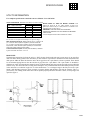
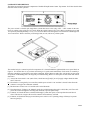
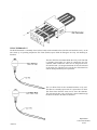
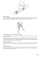
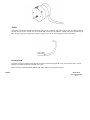
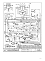
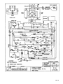
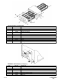
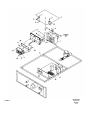
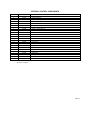
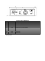
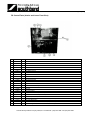
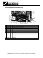
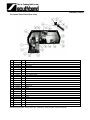
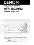
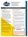
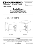
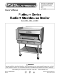
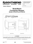
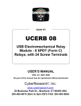
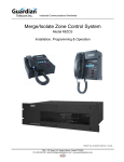
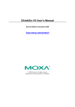
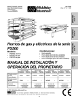
A MIDDLEBY COMPANY
TECHNICAL MANUAL
RAPID STEAM COUNTERTOP
CONVECTION STEAMER
MODEL RS-4E
This manual is intended for the use of Southbend Authorized Service Agencies and their
associates.
Service work should be performed only by a qualified technician who is experienced in,
and knowledgeable with the operation of commercial gas, electric, steam cooking
equipment.
WARNING:
Improper installation, service, or maintenance can cause
property damage, injury or death.
1100 Old Honeycutt Road • Fuquay, NC 27526 • (919) 552-9161 • FAX (919) 552-9798 • (800) 348-2558
Middleby Corp. Service Hot Line (800) 238-8444
RAPID STEAM
CONVECTION STEAME
(Manual Section ST)
NOTICE
Warranty will be void if
(A) Service work is performed by other than a Southbend Authorized Service Agency,
or
(B) Other than Genuine Southbend replacement parts are installed.
TABLE OF CONTENTS:
FOR INSTALLATION AND USERS GUIDE - CONSULT OWNER'S MANUAL - Part #1176560
Safety Precautions
Utility Information
Service
Operating Sequence
Component Description
Troubleshooting Guide
Performance Standard
Performance Check
Instructions - Removal and Replacement
Electrical Schematic Drawings
Parts List
2
3
3
4
5
11
15
15
16
17
20
LOCATION OF SERIAL AND IDENTIFICATION PLATES:
The serial plate with all voltage information is located on the exterior right body side at the upper rear comer. There is
also a product identification plate located on the front of the unit at the upper left top comer of the door showing the
model number and serial number only.
SAFETY PRECAUTIONS
The following words and symbols, found in this manual, alert you to hazards to the operator, service personnel or the
equipment. The words are defined as follows:
DANGER
This symbol warns of imminent hazards which will result in serious injury or death.
WARNING
This symbol refers to a potential hazard or unsafe practice which could result in
serious injury or death.
CAUTION
This symbol refers to a potential hazard or unsafe practice which may result in minor
or moderate injury or product or property damage.
This symbol refers to information that needs special attention or must be fully
understood even though not dangerous.
NOTICE
WARNING
BURN HAZARD
• Stand back when opening doors - hot steam or hot water may escape
from steamer.
• Unit, especially drain, must be cleaned daily and properly
maintained. Clogged drain can create burn hazard when door is
opened.
1100 Old Honeycutt
Road Fuquay, NC
27526 (919)552-9161
FAX (919) 552-9798
(800) 348-2558
SPECIFICATIONS
UTILITY INFORMATION
For complete specifications consult the Owner's Manual - Part #1176560.
UTILITY INFORMATION: ELECTRIC: One electric connection required.
WATER USAGE AT TIMED OR MANUAL COOKING: 0.08
MAX. AMPS PER LINE
gallons per minute at 45 p.s.i. water pressure in cavity. 0.16
TOTAL CONNECTED AMPS
1 PHASE
3 PHASE
gallons per minute at 45 p.s.i. water pressure in condenser. 0.24
208 V 60 Hz
47
28
total gallons per minute at 45 p.s.i.
220 V 50/60 Hz
44
27
IMPORTANT: UNIT MUST BE LEVEL FOR PROPER
240 V 60 Hz
40
24
OPERATION. WARRANTY WILL BE VOIDED FOR IMPROPER
380/220 V 50 Hz
26
15
INSTALLATION.
415/240 V 50 Hz
24
14
"All units shipped 3 Phase. Field convertible to 1 Phase.
480 V 60 Hz
20
12
Circuit must tie wired for maximum amps at required voltage.
Water Quality Specifications: Water Pressure, 60 p.s.i. maximum 30
p.s.i. minimum. Install a pressure regulator if pressure exceeds 60
p.s.i. In order to minimize service problems and to meet the warranty
requirements, a water treatment system (softener) is recommended
when water quality exceeds the limits stated.
Total Dissolved Solids (TDS»: 60 PPM (Parts Per Million). Hardness:
2 grains or 35 PPM. Ph Factor: 7.0 to 7.5.
DRAIN LINE:
The drain line connection size from the unit is 1" NPT (32 mm). Position the unit near, but not on top of, an open floor
drain. DO NOT directly plumb to the unit unless you also install an "open funnel" downstream of this connection in the
drain system. Make the drain line from the unit to the air gap above the "open funnel" as short as possible. There should
be no horizontal piping between the unit and the air gap above the "open funnel." The "open funnel" is intended to
eliminate any water from entering the steamer because of a blocked drain and it also prevents any back pressure within the
steamer cavity. The unit must be free-venting to the atmosphere. Any connection that allows the build-up of back pressure
in the unit such as a reduction in pipe size to a line smaller than 1" or a 90 degree angle in the line prior to the "open
funnel" drain discharge point may cause personal or property damage and therefore will void the warranty. This is a
pressureless, free-venting steam cooker and will not operate properly unless the drain line is short, at a steep angle, and
open! See figure 3.
PAGE 3
SERVICE
OPERATING SEQUENCE RS-4E
The RS-4E is a counter top pressureless steamer. When the power switch is turned on, the drain solenoid is energized
directly and it closes. The fast fill float is in the down position and the fast fill solenoid is energized through the "NC"
contact in Relay 1. This fills the cavity well with water. This is automatic regardless of timer position, as the water rises
to cover the elements it raises the low water float which energizes the Rl relay. The Rl relay when energized de-energizes
the fast fill solenoid and energizes the slow fill solenoid. (Refer to Figure 1 for fast and slow fill float locations.)
The R-1 Relay then sends power to the Limit Switch. Passing through the normally closed contacts and energizing the
contactor and condenser spray solenoid. The contactor when energized sends power to the elements and the elements
begin to heat the water.
All functions to this point are automatic when the unit is started up as long as the power switch is turned on and the door
is closed.
The temperature in the cavity well will continue to rise until it is up to boiling at which time a thermostat senses the well
temperature and opens up. This de-energizes the R-2 relay and turns the ready light on.
The control of the steamer is now governed by the timer. The timer has three positions. The first is Manual in which the
unit runs on full power continuously.
The second position is the Timed position. In this position a cook time is dialed in and after the timer counts down to zero
the timed out light will flash and the buzzer will sound and the unit will go into idle mode automatically.
The third position is the Idle position. In this position the unit will remain just below boiling temperature and ready for
use. The 500 watt heating element is energized. The unit can be brought up to full power by turning timer knob to manual
or setting a time.
PAGE 4
Rapid Steam
Convection Steamer
10/94
COMPONENT DESCRIPTIONS
The following section lists the main components of the RS-4E Rapid Steam Counter Top Steamer. It will also describe these
functions in the steamer operation.
The power switch is a double-pole single-throw switch that serves as the (only) "ON" - "OFF" control for the unit.
Power is coming to the switch in wires 7 and 8. When the switch is turned "ON," power then is switched to wires 9 and
10 respectively and independently (7 to 9), (8 to 10). Power then travels through wire 9 to term block 1 and through wire
10 to term block 6. With a volt meter you should get 208 (or 240) volts at any of these points:
The terminal strip is a connection point for components. It is located behind the right hand side access panel. Refer to
Figure 2. It is divided into six (6) sections each having 6 1/4" spade male terminations. Each section is essentially a
function, controlling or controlled by some other component. Each of them are made "Hot" (electrically) at some point
in operation. Understanding these can aid greatly in troubleshooting. Below is a description of each section and what its
function is.
[1] Always hot when switch is "On" (main "Hot"). Check between [l] and [6] to verify supply voltages should be either
208 or 240 volts.
[2] Hot when R-1 is energized by low water float, and the power switch is "On" and door is closed. It also allows the
contactor to energize the condensate solenoid.
[3] Hot when timer "Times Out" to "0" and the unit is in the Idle mode.
[4] Hot when timer is "Timing" or in "Manual" mode, also on initial startup when unit is cold (in idle), well T-stat will
power this section through R-2 activating main elements to provide quick heatup.
[5] "Common" or Neutral side that is switched off through [3] when door opens, to interrupt functions until door is
closed. This also de-energizes the slow fill contactors and condensory solenoid.
[6] "Common" or Neutral side always powered when power switch is "On." Operating voltage will always be present
between Q and [6].
PAGE 5
WELL THERMOSTAT
The Well Thermostat is a normally closed (Closed cold) switch mounted on the side of the well under the cavity. As the
unit comes up to operating temperature this T-stat (Switch) opens which De-Energizes R-1 relay coil initiating its
functions.
The Slow Fill Float is mounted inside the cavity well. This float
is normally closed when it is down. It controls the slow fill
solenoid, which controls the water level. It energizes the slow
fill solenoid as R-1 is energized and shuts off slow fill solenoid
as the water rises. This flow will cycle the slow fill solenoid on
and off during normal full power operations.
The Low Water Float is also mounted inside the cavity well.
This float is a normally open switch. It is open when it is down.
This float closes when the water level is above the elements.
This activates the R-1 relay coil. Power is then routed through
the Slow Fill Float to the Slow Fill Solenoid.
PAGE 6
Rapid Steam
Convection Steamer
10/94
DRAIN SOLENOID
The Drain Solenoid is a normally open solenoid valve that closes when energized. (Whenever power switch is "On,"
power goes to term stripe [3] and[6]. Valve remains dosed always when power switch is on, allowing water to fill and
remain in cavity well. It is located under cavity near rear. Turning unit off opens valve and drains well.
CONDENSOR, SLOW FILL, AND FAST FILL SOLENOIDS.
The condenser, Slow Fill and Fast Fill solenoids are all identical solenoids. All three solenoids are located immediately
behind the control panel.
The condenser solenoid valve is a normally closed (closed when NOT energized) solenoid valve which is activated
(simultaneously with main contactor coil) when ready R-1 is energized by the low water float. It is energized whenever
"Full Power" running is active, "Manual" or "Timed," NOT idle mode. (Controls water flow to condenser spray nozzle),
located in lower area behind control panel, in solenoid assembly.
SLOW FULL SOLENOID
The Slow Full Solenoid is a normally closed (closed when NOT energized) solenoid valve that is activated by slow fill
float when R-1 is energized (sufficient water). It cycles off and on as float rises and falls, maintaining water level in
well.
FAST FILL SOLENOID
The Fast Fill Solenoid is a normally closed (closed when not energized) solenoid valve providing a high volume quick
fill action energized when power switch is turned on. Remaining on only when R-1 is not yet activated. When water
level trips R-1 fast fill ceases, slow fill begins.
PAGE 7
TIMER
The Timer is essentially a motorized time switch, but also has a "Manual" and "Idle" position. It is the function selector,
allowing the user to set a "Timed" run, leave unit in "Idle" or leave unit in "Manual," running full-power continuously. In
Idle, the unit is kept up to temperature ready for full power use, while conserving both water and electricity.
DOOR SWITCH
The Door Switch is a normally open magnetic activated switch energizing the R-3 relay coil when the door is closed.
Magnet is mounted inside door at bottom near center.
Door Switch is located immediately behind front frame under cavity, mounted on panel.
PAGE 8
Rapid Steam
Convection Steamer
10/94
R-1RELAY
The R-1 Relay is a double pole double throw relay energized by the low water float when the water level in the well
rises above the elements.
BELOW this trip point the fast fill solenoid is energized (door must be closed). ABOVE this trip point, TWO
SEPARATE actions are initiated.
1. Power now travels to term block [2] on to limit thermostat, then onward to contactor coil and condensate solenoid
simultaneously.
2. Power now travels to the idle element (which will now run continuously) and the slow fill float which will then
cycle slow fill solenoid off and on to maintain water level.
Once R-1 relay is activated on startup, it remains energized continuously as long as unit is running.
R-2RELAY
The R-2 Relay is the well-thermostat controlled relay. It is identical to R-1, R-3 and R-4 (DPDT). When the unit is
started cold the well thermostat is in a "Closed" state, which energizes R-2 Ready Coil. In this "Cold" condition R-2
provides "Full Power" (Main Elements) startup when in the "Idle" position on the timer.
When unit comes up to operating temperature, the well thermostat opens, de-energizing R-2 Relay Coil. This transfers
power to the other set of R-2 contacts and activates two (2) separate actions.
1 The "Ready" light is illuminated (and will remain so as long as unit is on).
2 The Buzzer and "Timed Out" light will now BE ALLOWED to activate IF and WHEN a time is set on timer and
ALLOWED TO TIME OUT.
R-3 RELAY
R-3 Relay is the door-switch controlled relay. It is identical to R-1, R-2 and R-4, (DPDT). Its function is to allow
certain activities to take place ONLY when the door is closed. They are:
1. Fast fill
2. Timer count down
3. Slow fill
4. Main contactor coil
5. Condenser spray
6. Buzzer
7. Timed out light
The R-3 also ACTIVATES R-4 relay when the door is opened after timing down to "O." R-4 then "latches" itself
energized which leaves "Timed Out" light and buzzer de-activated in idle mode. Re-settine a new timmer oneration
releases the "Latch" of R-4.
PAGE 9
R-4 RELAY
R-4 Relay is the "Latching" relay. It is identical to R-1, R-2 and R-3 (DPDT). Its purpose is to allow the operator to
respond to the continuous buzzer after timing down to "0" by simply opening the door. R-3 energizes R-4 when the door
is opened. R-4 then "Latches," holding itself energized. Closing the door again leaves the unit in timed out idle without
the buzzer or timed out light staying on. When a new time is selected on the timer or the "Manual" mode is chosen, the
"Latch" on R-4 is released allowing the buzzer and timed out light to again operate when the timer times down to "0."
LIMIT SWITCHES A & B
The Limit Switch is a bulb and capillary type limiting device which has two SPDT switches (independent) which "trip"
at two different temperatures which are factory set and not adjustable. Switch "A" is normally open and under normal
operation will not be activated.
A capillary bulb is attached to the side of one element tube. Sensing the operating temperature of the element. As lime
or calcium deposits begin coating the exterior of the elements, the heat energy is NOT transmitted into the water,
thereby causing the elements to operate at a higher temperature. When limit Switch "A" senses this temperature rise and
trips, it powers the "De-Lime" light, signaling the operator to perform cleaning and de-scaling maintenance. The unit
will continue to run, although not as efficiently.
Switch "B" is normally closed and set to trip at a higher temperature than Switch "A." Switch "B" is the final "Dry-Fire"
or "Hi-Limit" protection. It shuts off the Main Contactor coil in the event of significant temperature rise.
If scale conditions are extremely bad and element temperature rises significantly, this switch (B) will now trip. It will
also trip in the event the Low Water Float should happen to stick "Up" and a "Dry-Fire" condition takes place.
PAGE 10
Rapid Steam
Convention Steamer
10/94
SERVICE
TROUBLESHOOTING GUIDE
The following Troubleshooting Guide is designed to aid in troubleshooting components on the RS-4E RapidSteam
Steamer. Before starting service on the RS-4E verify the steamer has the proper power supply, water supply and drain
connections. The access column below tells you the access area that allows the easiest access to components. The
abbreviations used are as follows.
RR - Rear of steamer
RT - Right access panel
CAV. - Interior cavity LT - Left access panel
CP - Control Panel
Symptom
Power Switch is turned
on but unit does not
operate.
1.
Cause
Check Access
Breaker tripped or no power into unit.
1.1 Check to see that Breaker is on.
1.2 Check for proper supply RR voltage at terminal block
-rear of unit. Voltage should match rated voltage on
unit Serial Plate.
Unit is on but does not
fill on startup.
2.
Defective Power Switch
2.1 Verify voltage into and out of CP switch in "On"
position. Verify voltage between term strip [1] and
[6].
3.
Loose wire connection
3.1 Disconnect power to unit. CP Remove control panel
and RT right side panel and inspect for wire terminals
loose or wires disconnected.
1.
Faulty or mis-adjusted Door Switch or
faulty R-3 Relay. (R-3 not being
energized)
1.1 Remove Right Side Panel. RT Verify R-3 activates
when door closes.
1.2 If R-3 does not activate check RT
voltage across coil.
• Voltage across coil - door switch OK, relay is bad.
• No voltage across coil -door switch is not being
activated by door or door switch is bad.
2.
Faulty Fast-Fill solenoid. (R-3 is being
energized.)
2.1 Check for voltage across RT solenoid coil. (TB [5]
and "NC" contact on R-1 Relay)
• Voltage across coil - no action, solenoid is bad.
• No voltage — re-trace circuit and R-3 related
items.
3.
Faulty Drain solenoid. (Well will not
hold water)
3.1 Listen for water filling, unit RT may fill partially,
even if drain solenoid has failed.
3.2 Check voltage across drain solenoid coil. (TB [j] and
[6]) RT
PAGE 11
Symptom
Does not fill in
"Timed Out"/Idle
Cause
4.
Faulty R-2 Relay or Well TStat
Ckeck
4.1 Remove Right Side Panel.
R-2 should activate imme-
position at startup
(R-2 energized cold by well
"Ready" light is on
T-start powers fast fill in
immediately at cold
"Idle" startup.)
startup
[R-2 is only energized when
voltage across coil.
unit is cold.]
• Voltage across coil - Relay
is bad.
Access
RT
diately when power switch is
turned on. (Door closed)
4.2 If R-2 does not activate check
RT
• No voltage across coil —
well T-stat is bad.
Unit runs but slow
fills continuous.
1.
Slow Fill Float stuck in
"Down" position.
1.1
Check Slow Fill Float for
free movement on stem and
CAV
inside baffle tube.
Cooking compartment is flooding.
Too much water in
well
Normal running
should hear water
fill cycling off and
on.
Fast filling and
contactor cycles
1.
Faulty "Slow Fill" float
1.1
on/off.
Remove right side panel.
Shut power off. Disconnect
RT
Slow Fill Float leads (red).
Check continuity of switch
Slow fill water is
as you raise and lower float.
not maintaining
(Higher and to the left,
sufficient level.
INSIDE protective tube
baffle) Do this test while the
float is still HOT from
operation of unit. Sometimes
a float switch will test "OK"
COLD.
2.0 Faulty slow fill solenoid
2.1
If float switch tests good
RT
check voltage across slow fill
solenoid coil (TB [5] and float
switch) • No voltage - check R-3
related functions as it can
affect slow fill circuit.
• Voltage present - no filling
action: solenoid is bad or
plugged. Replace.
3.0 Low water pressure
PAGE 12
3.1
Check for minimum 30 p.s.i.
Rapid Steam
Convection Steamer
10/94
Symptom
"De-Lime" light
1.
comes on.
Cause
Check
Access
Elements are coated with
1.1 Check elements.
CAV
deposits buildup, or limit
T-stat out of calibration.
• Clean elements - limit
thermostat bulb damaged
Unit still runs ok.
or T-stat needs calibration.
If T-stat bulb (on element)
is not crushed or damaged,
see limit thermostat cali
bration procedure.
• Coated/covered elements clean elements following
Southbend recommended
cleaning procedure.
"De-Lime" light
comes on.
1.
Elements severely coated
with deposits buildup.
1.1 Clean elements following
Southbend recommended
CAV
cleaning procedure. Repeat if
Unit has shut down.
necessary until elements,
well, and floats are entirely
Elements not on.
Unit operates
normally, heats up
clean.
1.
T-stat loose (not sensing well
temp).
OK, but "Ready"
1.1 Check that bracket securing
T-stat is tight and that
RT
CP
bottom of
light does not come
(T-stat opens to de-energize
T-stat is flat against side of
on.
R-2, no contact then powers
well.
ready light.)
2.
Loose or broken wires on T-
2.1 Check wires that go from
RT
stat or R-2 relay.
terminal block to T-stat and
CP
R-2 relay.
3.
Light burned out.
3.1 Check voltage across Ready
CP
Light after unit is heated to
operating temperature (5
minutes).
Unit operates but is
slow.
1.
Incorrect (low) voltage.
1.1 Check voltage at rear
terminal block to see if it
RR
matches that on unit serial
plate.
2.
Faulty contactor.
2.1 Check that each power input
RR
lead has amperage draw
comparable to rating on
serial plate
Unit will not operate
in idle mode.
1.
Timer switch contacts
failure.
1.1 Check for (208-240) voltage
between terminal strip
RT
sections [3] and [6].
PAGE 13
Symptom
Unit will not operate
in Manual Mode or
Cause
1. Timer Switch contacts.
Timing Mode
Unit operates in
"Timing" mode but
Check
Access
1.1 Check for operating voltage
(208-240) between TB[4] and
RT
[6].
1. Timer Motor faulty.
1.1 Check for voltage across
Timer Motor leads when dial
timer does not count
is set to a time anywhere in
down.
the "0" to "55" scale.
CP
Unit "Fast Fills"
continuous, contactor
never energizes
1. "Low Water" float stuck
down.
1.1 Check that Float (lower and
to the right) moves freely up
and down on stem.
CAV
elements.
2. Faulty Low Water Float
2.1 Remove Right side panel.
RT
(switch contacts never
Check to see that R-1
"Close"). .
energizes when water level
raises float.
or
2.2 If R-1 does NOT energize
Faulty R-1 Relay.
RT
check voltage across coil.
• No voltage - Float switch
is bad.
• Voltage present/no action
- R-1 relay is bad. Replace.
Unit operates
normally. Then
1. Supply breaker tripped.
1.1 If Breaker is tripped, leave
power off, remove control
shuts off. No lights
panel and Right and Left
illuminated on
side panels and check for
panel.
loose wires or connections or
pinched/damaged wires.
2. Loss of water supply.
2.1 Check that water supply has
not been shut off or that
facility water supply is still
OK.
PAGE 14
Rapid Steam
Convection Steamer
10/94
PERFORMANCE STANDARD:
The RS-4E should come up to operating temperature and the Ready Light will come on after approximately 4 minutes,
from cold start.
PERFORMANCE CHECK:
The following items should be checked before or within the first 30 days of operation by a Southbend Authorized
Service Agency, and on a routine maintenance schedule thereafter.
1. Verify equipment is level.
2. Verify proper electrical characteristics — Voltage, cycle, phase.
3. Check ventilation.
4. Check electrical connections — external and internal.
5. Check door for proper alignment, seal, and adjustment.
6. Check timers and switches for proper installation and operation.
7. Verify proper water pressure and line size.
8. Verify proper drain set up. Must be free venting9. Explain importance of keeping elements and floats free of scale. Cover maintenance as explained in Owners Manual.
PAGE 15
REMOVAL AND REPLACEMENT INSTRUCTIONS
FLOATS
1. Remove control panel, left and right side panels.
2. Disconnect wire leads of faulty float (or cut wires off).
3. Using 1/2" open end wrench, remove float from inside well. Wires or terminals will have to be cut off to remove.
Terminals will NOT fit through float mounting.
4. Install new float by feeding wires through mounting, pulling through from below. Tighten float with 1/2" open end
wrench.
5. Attach new terminals to wire ends. Plug into original locations.
SOLENOID VALVES/FLOW CONTROL
Positively identify and prove that a solenoid is defective before attempting replacement.
1.
2.
3.
4.
5.
6.
7.
Remove control panel and left side panel.
Temporarily remove the limit thermostat and bracket from its location on the element retainer stops.
Disconnect the three (3) copper tubing connections from the solenoid assembly.
Remove the securing screw holding the solenoids in place (small bracket in front of solenoid assembly).
Solenoid assembly can be pushed back, turned and then pulled forward/sideways to remove.
Leads will need to be disconnected from origins, to remove assembly.
Remove and replace defective solenoid or flow control. Note arrangement, some care is required to re-assembly.
Note direction arrow on flow regulator (points towards rear of unit). TIGHTEN CONNECTIONS.
8. Re-install assembly into brackets.
9. Re-attach leads carefully. Refer to wiring diagram.
10. Re-attach copper tubing connections.
11. Install limit thermostat and bracket.
12. Install control panel and left side panel.
RELAYS
1. Remove control panel and right side panel.
2. Remove defective relay. Note wire/terminal locations.
3. Install new relay.
4. Replace control panel and right side panel.
CONTACTOR
1.
2.
3.
4.
PAGE 16
Remove control panel and right side panel.
Disconnect wires and leads from contactor.
Remove contactor ((2) screws, diagonal).
Re-install control panel and right side panel.
Rapid Steam
Convection Steamer
10/94
PAGE 17
PAGE 18
Rapid Steam
Convection Steamer
10/94
PAGE 19
PARTS
NOTICE:
INSTALLATION OF OTHER THAN GENUINE SOUTHBEND PARTS WILL VOID THE
WARRANTY OF THIS EQUIPMENT.
The serial plate is located on the right upper rear comer. There is also an Identification Plate mounted to the front of the
door the left top comer that will supply model and serial number.
Replacement parts may be ordered either through a Southbend Authorized Parts Distributor or a Southbend Authorized
Service Agency.
When ordering parts, please supply the Model Number, Serial Number, Part Number, Description, plus Finish, Type of
Electrical Characteristics as applicable.
For parts not listed, consult a Southbend Authorized Parts Distributor or Southbend Authorized Service Agency. If
necessary, please consult Southbend Parts Department for assistance.
FOR MODEL NUMBER - RS-4E Rapid Steam
REPLACEMENT PARTS INDEX
see pages
Legs and Outer Body Parts
Door Panel Assembly
21
22
Steamer Cavity Interior Parts
23
Heating Element and Thermostat
24
Terminal Block (Rear of Steamer)
24
Water Solenoid Assembly
25
Internal Control Components
26
Control Panel Components
28
MISCELLANEOUS PARTS NOT SHOWN IN DRAWINGS
PART NO.
1176561
1176560
4460002
PM-162
4450020
4450021
PAGE 20
DESCRIPTION
Cleaning Instructions RS-4E
Owners Manual
Technical Service Manual
Cleaning Pad
SteamMaster Descaler - 24 Pack
SteamMaster Descaler - Master Pack (Contains 8 of the 4450020)
Rapid Steam
Convection
Steamer
10/94
ITEM
1
2
3
4
5
6
7+
8+
9
9A*
10
11*
12
13
14
15
16
17
18
PART NO.
1176405
1176401
1176391
1176376
1176311
1176407
1332048-1
1332048-2
PH-423
PH-292
1173198
1172964
1163561
1146390
1332076
1332003
1176403
1176404
DESCRIPTION
Door Assembly (complete)
Drip Tray
Shield
Side Panel
Rear Cover
Insulation
Door Hinge - LH
Door Hinge-RH
Bronze Bushing (for Door Hinge)
Nylon Washer (Fits Between Door and Hinge)
Door Striker
10-241/2 Stainless Steel Hex Screw (Hold door striker on)
Leg
10-24x1
Blank For Door Hinge
Door Shim
Front Panel Bracket
Rear Panel Bracket
Serial Plate Location
* Not shown on drawing.
+ If door is hinged on right hand side of steamer the hinges would switch position top to bottom.
PAGE 21
DOOR PANEL ASSEMBLY
ITEM
PART NO.
1
1176402
Door Weld Assembly
2
1173223
Insulation Block (Foam)
3
1173195
Retainer Panel Assembly
4
1172994
Molded Silicone Gasket
5
1173200
Inner Panel Assembly
6
1173188
Door Latch
7
1173199
Door Latch Retainer
8
1176255
Door Magnet
9
1176337
Magnet Support Block
10
1173224
1/4-20x5/8 Slotted Screw
11
1146321
8 - 32 x 3/8 Round Head Screw
12
6600334
6 - 32 x 3/8 Self Tapping Screw
13
PM-141
Plug Button 1/4 Nylon
PAGE 22
DESCRIPTION
Rapid Steam
Convection
Steamer
10/94
STEAMER CAVITY INTERIOR PARTS
ITEM
PART NO.
DESCRIPTION
1
1176318
Well Cover Deflector
2
1174587
Cavity Side Rack
3
1174924
Float Switch, Water Rll (Red Leads) Normally Open
4
PE-193
Float Switch, Low Water (Black Leads) Normally Closed
5
1176312
Float Baffle Tube (Slow Fill)
6
1176419
Chain, Steamer (Three Links)
7
1176313
Bracket, Baffle Tube Chain
8
1333041
Rack Mounting Studs 1/4 - 20 SPC
9
PH-238
Lock Nut For 1333041
PAGE 23
HEATING ELEMENT & THERMOSTAT
ITEM
PART NO.
1
1176485
DESCRIPTION
208V Element Assembly
1176486
220V Element Assembly
1176487
240V Element Assembly
1176488
380V Element Assembly
1176489
415V Element Assembly
1176490
480V element Assembly
2
1176492
Element Gasket
3
1146402
Nut 1/4-20 Hex
4
PE-182
Thermostat
5
6600430
Lock Nut
6
1176315
Hold Down Bracket (T-Stat)
7
1176589
Brass Plug
TERMINAL BLOCK (Rear of Steamer)
PAGE 24
ITEM
PART NO.
1
PE-023
DESCRIPTION
Terminal Block (1 Section) Assembly 1174700
2
1176324
Water Inlet Plate Weld Assembly
3
1173428
In Line "Y" Strainer
4
P-4119
5
1176409
Condenser Tube
6
1174620
Spray Nozzle 1/8 NPT .34 GPM
1160031
Ground Lug
Brass Elbow 1/4 x 1/8 NPT
Rapid Steam
Convection Steamer
10/94
WATER SOLENOID ASSEMBLY
ITEM
PART NO.
1
1174948
DESCRIPTION
3/8 CC-1/8 NPT Female
2
PP-269
1/8 NPT Male Tee
3
1161541
1/8 NPT Male/Female
4
P-4119
1/4CC-1/8 NPT Male Elbow
5
PP-501
1/8 NPT Coupling
6
1176384
1/8 NPT Nipple
7
1176254
1/8 NPT Female Tee
8
PP-636
Flow Regulator
9
PP-275
3/8 NPT M-1/8 NPT M Elbow
10
PP-286
3/8 NPT M-1/4CC
11
1176372
1/4 Diameter Copper Tubing
12
1176385
3/8 CC-1/8 NPT Male
13
P5552
1/4CC-1/8 NPT Male
14
1174933
Solenoid Water Valve 240 (VAC)
15
1174921
Drain Solenoid
16
1-3195
17
1176386
Brass Fitting 68C-8-8
(RS-4E) Solenoid Assembly
PAGE 25
PAGE 26
Rapid Steam
Convection
Steamer
10/94
INTERNAL CONTROL COMPONENTS
ITEM
PART NO.
1
1173448
Contactor
2
1176316
Contactor Bracket
3
1176493
High Limit
*
PM-019
5/8 Clamp For High Limit Bulb
4
1176363
Mount, Insulation Shield Door Switch
5
1176375
Component Slide Pan Weld Assembly
6
6600334
Screw, 6 - 32 x 3/8 Stainless Steel TC
7
1146388
Screw, 4 -40x1/2 Slot, 2I\I
8
1172327
Nut #4-40 Hex
9
PE-185
Door Switch
10
1109900
Buzzer, 240V (Used on units before 95B93610)
1175712
Buzzer, 220V (Used on units after 95B93609)
11
1146402
Nut 1/4-20 Hex Head
12
1146358
Screw, #8 - 32 x 5/8 Round Head
13
1146406
Nut 8-32 Hex
14
1146501
Washer 3/16 Lock
15
1176520
High Limit Switch Bracket
16
1146304
Screw #10 x 1/2 Truss Head
17
PE-179
Relay (Clear) 10Amp, 240V
18
1170335
Terminal Strip
*
1170336
Marker Strip
19
1161664
Bushing, SNAP, 7/8
*
1176388
Transformer (480V to 240V, 75VA)
*
1176509
Fuse, 3/4A, 600V
*
DESCRIPTION
Not shown on diagram.
PAGE 27
CONTROL PANEL COMPONENTS
ITEM
PART NO.
1
1176399
Light Assembly Amber (Light only 6600030)
2
1176417
Light Flashing G Amber (Light only 117-6413)
3
1176416
Timer 208 - 240V - 60Hz/60 Minute
1176436
Timer 208 - 240V - 50Hz/60 Minute
4
1174935
Switch Lighted, Water Proof
5
1176360
Control Panel (Used on all units before 95B93610)
1176877
Control Panel Weld Asm. (Used on all units after 95B93610)
6
1170337
Knob (For Timer.)
7
1174926
Poly Panel
…
1176394
Control Panel 60 Hz
…
1176437
Control Panel 50 HZ
* Not shown on drawing.
… Complete assembly.
DESCRIPTION
RAPID STEAM - COUNTERTOP
CONVECTION STEAMER
Litho U.S.A.
PART NUMBER 4460002
5-95
1100 Old Honeycutt Road
Fuquay, NC 27526
(919)552-9161
FAX (919) 552-9798
(800) 348-2558
A Middleby Company
R2 Control Parts (Interior and Lower Front View)
Key
Part Number
Qty
1
PE-193
1
2
Description
Low Water Float
1178007
1
208V Middle Element
1178008
1
220V Middle Element
1178009
1
240V Middle Element
1178010
1
380V Middle Element
1178011
1
415V Middle Element
1178012
1
480V Middle Element
1174561
2
208V Outer Elements
1174616
2
220V Outer Elements
1174562
2
240V Outer Elements
1174563
2
380V Outer Elements
1174617
2
415V Outer Elements
1174564
2
480V Outer Elements
4
1178677
1
Valve Rod Weld Assembly
5
1177440
1
Well Thermostat
6
1177996
1
High Limit
7
1178019
1
High Limit Bracket
N/S
1176315
1
Well Thermostat Bracket (Not Shown)
N/S
1166801
1
Brass Elbow to Drain Valve (Not Shown)
N/S
1176667
1
Drain Valve (Not Shown)
N/S
1166170
1
Brass Connector from Drain Valve to Drain Tube (Not Shown)
N/S
1177775
1
Drain Tube (Not Shown)
N/S
1-3195
1
Brass Connector from Drain Tube to Drain Pipe (Not Shown)
8
1333041
4
Rack Mounting Studs, 1/4-20 w/ PH-238 Nuts (Not Shown)
3
1100 Old Honeycutt Road * Fuquay-Varina, N.C. 27526-9312 * (919) 762-1000 * Fax (919) 552-9798
A Middleby Company
R2 Control Parts (Bottom Interior and Rear View)
Key
Part Number
Qty
Description
1
1177653
1
Terminal Strip
2
1178511
1
Wiring Harness (Includes front control panel section)
3
1177878
1
Element Leads (Assembly of 6 Wires - White)
4
1173448
1
Contactor
5
1174933
1
Water Fill Solenoid
6
1178514
1
Water Supply Tube
7
1178515
1
Condensate Supply Tube
8
1178513
1
Cavity Fill Tube
9
PP-636
1
Flow Regulator
10
1177418
3
Main Power Leads (Black)
11
1175547
1
Grounding Lug
12
1177361
1
(3) Pole Terminal Block
13
1177877
1
Vent Hose
14
1173428
1
In-Line Strainer
15
1174620
1
Condensate Spray Nozzle
1100 Old Honeycutt Road * Fuquay-Varina, N.C. 27526-9312 * (919) 762-1000 * Fax (919) 552-9798
A Middleby Company
R2 Control Panel Parts (Rear View)
Key
Part Number
Qty
1
1161664
1
7/8" Snap Bushing
2
1177653
1
Terminal Strip
3
1177360
1
Relay Socket
4
1177363
1
Gasket, Relay
5
1177359
1
Relay, 240V, Sealed
6
1146397
4
8-32X5/8, SS, Phil, Pan Head Screw
7
1177377
1
Wire Tie, 6"
8
1146319
1
Screw, 6-32X1/2, Screw
9
1175712
1
Buzzer assembly
10
1178341
1
Timer
A
1178270
1
Switch, actuator rod
B
1178347
2
Seal, shaft (1) Behind Timer Knob
C
1178338
1
Retaining ring
D
1178339
1
Washer
E
1179932
1
Spring
12
1177865
1
Nut, Bronze 5/8-18
13
1178339
1
Washer
14
1178642
1
Gasket
15
6600430
5
Locknut
16
1146320
2
Screw, 6-32X1, Roundhead
17
1178430
1
Door Switch
18
1177864
1
E-Clip, SS, .375 Dia. Shaft
19
1177396
2
Locknut, 6-32 SS
11
Description
Door Switch Actuator
1100 Old Honeycutt Road * Fuquay-Varina, N.C. 27526-9312 * (919) 762-1000 * Fax (919) 552-9798
A Middleby Company
R2 Control Panel Parts (Front View)
NOTE: The entire Control Panel Assembly can be ordered as part number 1178507.
Key
Part Number
1
1178403
Qty Description
1
Panel, control, weld assembly
2
1181616
1
Polypanel
3
1178700
1
Power Switch (was 1174935)
4
1177773
1
Valve lever weld assembly
5
1177770
1
Valve lever bushing
6
1170337
1
Timer Knob
7
1178330
1
Red "De-Lime' Light
8
1178329
1
Amber "Ready" Light
110 Old Honeycutt Road * Fuquay-Varina, N.C> 27526-9312 * (919) 762-1000 * Fax (919) 552-9798
R-2 Part's List
1174935
PE-193
1177359
1177360
1177363
1177361
1177362
1174933
1177440
1177996
PE-185
1146388
6600030
1173448
1177441
PP-636
1174587
4440451
1178647
1176667
1178341
1170337
1174620
1177080
1176328
1177775
1332048-1
1332048-2
1333041
6600430
PH-238
PH-292
PH-423
PM-019
PM-141
PP-439
1178268
1177400
1178143
1177836
1179551
1179553
PP-275
POWER SWITCH
LOWER WATER FLOAT
240V SEALED RELAY
RELAY SOCKET
RELAY GASKET
TERMINAL BLOCK 3 POLE AT REAR
TERMINAL BLOCK 4 POLE AT REAR
WATER FILL SOLENOID
WELL THERMOSTAT
HIGH LIMIT BEGINNING SER# 97A 19594
DOOR SWITCH
SCREW FOR DOOR SWITCH
READY LIGHT DE-LIME LIGHT
CONTACTOR
POLYPANEL.
FLOW CONTROL
SIDE RACK GUIDES
DOOR ASSEMBLY PRIOR 8/14/98
DOOR ASSEMBLY BEGINNING 8/14/98
DRAIN VALVE
TIMER
TIMER KNOB
SPRAY NOZZLE
DOOR STRIKER (CAST)
EXTERIOR COVER
DRAIN TUBE
LEFT DOOR HINGE
RIGHT DOOR HINGE
RACK MOUNTING STUD
LOCKNUT
LOCKNUT ¼ -20
NYLON WASHER
BRONZE BUSHING
HOSE CLAMP
NYLON PLUG BUTTON
'T FEMALE
WELL COVER DEFLECTOR COVER ELEMENTS
AMBER LIGHT 240V
LIGHT ASM. 250V (6600028 LIGHT ONLY)
HOSE FITTING
90 DEGREE ELBOW
FITTING 3/8 X ¼ HOSE
90 DEGREE ELBOW
1174561 208V ELEMENT
(2 IN UNIT)
1178001 208V ELEMENT
1174616 220V ELEMENT
(2 IN UNIT)
1178008 220V ELEMENT
1174562 240V ELEMENT
(2 IN UNIT)
1178009 240V ELEMENT
1174563 380V ELEMENT
(2 IN UNIT)
1178010 380V ELEMENT
1174617 415V ELEMENT
(2 IN UNIT)
1178011 415V ELEMENT
1174564 480V ELEMENT
( 2 IN UNIT)
1178012 480V ELEMENT
WHEN CHANGING ELEMENT FOR SERIAL NUMBERS PRIOR 97A19594
MIDDLE ELEMENT ORDER HIGH LIMT KIT 4440462 ALSO
1177361 208V TERMINAL BLOCK
1177361 220V TERMINAL BLOCK
1177361 240V TERMINAL BLOCK
1177362 380V TERMINAL BLOCK
1177362 415V TERMINAL BLOCK
1177361 480V TERMINAL BLOCK
PART NUMBER
PH-422
1332076
1178266
1178651
1178534
1178525
1178411
1177770
1178389
1178494
1175708
1178276
1178370
1178299
1178256
1176561
1161525
1173448
1178397
1178311
1178442
1178524
1178552
1178265
1178527
1178255
1179962
1176797
1178167
1178171
1178522
1178410
1333045
1178353
1178359
1178526
1178354
1178360
1178355
1178361
1178358
1178364
1178332
1178423
1178422
PI-M23
1178318
1178317
1178545
DESCRIPTION
BELLEVILLE WASHER, 1/4 ID
BLANK, DOOR HINGE
BOX WELD ASM., REAR
BRACKET, COMPONENT SIMPLE
BRACKET, ON/OFF SWITCH
BRACKET, VENT TUBE, EZ-3
BRACKET.WIRE HANGER
BUSHING, VALVE LEVER MOUN
BUSSMAN FUSE BLOCK.30A
BUSSMAN FUSE BLOCK,60A 48
BUZZER, ADJUSTABLE, 220V,
CAM ACTUATOR, STEAMER
CAVITY INSULATION
CAVITY WELD ASM, EZ-3
CLAMP, HEATER
CLEANING INSTRUCTIONS,RSCONTACTOR, 2-POLE,240V,30
CONTACTOR, 63A.240V COIL
CONTROL PANEL S/A, EZ-3
CONTROL PANEL W/A, EZ-3
COVER ASM.,POOL
COVER W/A, DRAIN BOX, EZCOVER W/A, DRAIN, EZ-3
COVER, BOTTOM
COVER, REAR STEAMER, EZ-3
COVER,EXTERIOR,SIMPLE STE
COVER.REMOVABLE BUSS
DESCALER, 3.50Z PKG (100G
DOOR ASSEMBLY COMPLETE, EZ
DOOR INSUL. BLOCK
DRAIN BOX WELD ASM., EZ-3
DRAIN PAN WELD ASM.
DRAIN VENT TUBE ( AIR VEN
DUAL HEATING ELEMENT
DUAL HEATING ELEMENT
ELBOW, 90 DEG. 1-NPT FEM,
ELEMENT BLOCK, 220V,CENTE
ELEMENT BLOCK, 220V,OUTER
ELEMENT BLOCK, 240V.CENTE
ELEMENT BLOCK, 240V.OUTER
ELEMENT BLOCK, 480V.CENTE
ELEMENT BLOCK, 480V,OUTER
FITTING,3/4 HOSE ID X 1/2
FITTING,3/4" KYNAR HOSE.E
FITTING, FLOAT SWITCH
FLANGE BUSHING, 1/4ID BRO
FRONT FRAME WELD ASM
FRONT TOP CROSSMEMBER W/A
FUSE, 10AMP
UNITS
EA
EA
EA
EA
EA
EA
EA
EA
EA
EA
EA
EA
EA
EA
EA
EA
EA
EA
EA
EA
EA
EA
EA
EA
EA
EA
EA
EA
EA
EA
EA
EA
EA
EA
EA
EA
EA
EA
EA
EA
EA
EA
EA
EA
EA
EA
EA
EA
EA
QTY
16
2
1
1
1
2
2
1
1
1
1
1
1
1
4
1
1
1
1
1
1
2
2
1
1
1
1
2
1
1
2
1
1
1
2
2
1
2
1
2
1
2
2
2
1
2
1
1
2
1178392
1178390
1178495
1178391
1178096
1178227
1178325
1180953
1332048-1
1332048-2
1178483
1178386
1178369
1178371
1178418
4440478
1170337
1177079
1177317
1177078
1178485
1178486
1178329
1178330
1175547
1178374
1178387
1178367
1178643
1178351
PH-292
1178342
1178344
1178345
1178169
1178105
1178106
1177081
1172949
PM-141
1178319
1178684
1178352
1333041
1178337
1177086
1178338
6600402
1178343
1175712
FUSE, 2.5 AMP
FUSE, 30 AMP
FUSE, 50 AMP, CLASS G
FUSEBLOCK, CONTROLS
GASKET, DOOR
GASKET, SIDE PANEL
GASKET, CONTROL PANEL EZ-3
HANGER,HOSE,COMBI/EZ STEA
HINGE, LT DOOR
HINGE, RT DOOR
HOSE, 1 1/2"ID,SILCONE
HOSE.3/4" ID SILCONE
INSULATION, BACK PANEL
INSULATION, BOTTOM
INSULATION, FRONT CAVITY
KIT, DRAIN BOXES.STACK EZ
KNOB
LATCH ARM, CAST
LATCH ASSEMBLY, STEAMERS
LATCH COVER PLATE, CAST
LEG,4" S/S.EZ-3 (FRONT)
LEG,4" S/S,EZ-3 (REAR)
LIGHT, INDICATING.AMBER
LIGHT, INDICATING.RED
LUG, GROUNDING
MAIN POWER LEADS
MANUAL, EZ-3 STEAMER
METAL OXIDE VARISTOR
NIPPLE, CLOSE, 1/2" NPT
NYLON INSERT NUT
NYLON WASHER
O-RING, VALVE SHAFT
PAN Z-BRACKET.LEFT
PAN Z-BRACKET, RIGHT
PANEL ASM.,DOOR EZ-3
PANEL ASM., INNER DOOR
PANEL, GASKET RETAINER,EZ
PIN, .250 DIA, SS, CAST L
PIPE ALUM.1" SCHEDULE 40
PLUG BUTTON, 1/4 NYLON
POLYPANEL W/TIMER
POT FILLER
POTENTIOMETER.TDR
RACK MOUNTING STUDS, 1/4-2
RELAY, TIME DELAY, 120V
RETAINER, CAST LATCH
RETAINING RING
RING,RETAINING S.S.
ROLL PIN
S/A BUZZER, 220V
EA
EA
EA
EA
EA
EA
EA
EA
EA
EA
FT
FT
EA
EA
EA
EA
EA
EA
EA
EA
EA
EA
EA
EA
EA
EA
EA
EA
EA
EA
EA
EA
EA
EA
EA
EA
EA
EA
FT
EA
EA
EA
EA
EA
EA
EA
EA
EA
EA
EA
2
3
2
1
1
2
1
2
1
1
N/A
N/A
1
1
1
1
1
1
1
1
2
2
1
1
1
3
1
1
1
8
2
1
1
1
1
1
1
1
1
2
1
1
1
8
1
1
1
1
1
1
1178347
1178373
1177318
1178234
1172951
1178113
1178644
1179932
1177082
1178654
1178655
1178379
1177080
1178270
1178340
1178533
1178430
1174302
1178341
1176388
1178439
1178261
1178376
1178388
1178425
1178444
1176878
1180460
1178324
1178652
1178394
1178650
1178395
SEAL, SHAFT
SHIELD,HEAT TRANSFER
SHIM, CAST STRIKER
SIDE PANEL.SIMPLE STEAM
SLEEVE, RUBBER 1 1/4"1D X
SLIDE RACK, 3 PAN STEAMER
SLIDE RACK, 5 POS. 3 PAN
SPRING
SPRING, DOOR HANDLE
STAND W/DRAIN, EZ
STAND, EZ
STEAM TRAP
STRIKER, CAST
SWITCH ACTUATOR ROD
SWITCH, FLOAT
SWITCH, POWER S/A
SWITCH.DOOR S/A.SIMPLE ST
THERMOSTAT, ELEMENT, 2001
TIMER, MECHANICAL
TRANSFORMER, 480 TO 240,7
TROUGH SCREEN ASM.
TUBE & BOX TOP W/A
TUBE, VALVE ACTUATOR
VALVE LEVER WELD ASM
VALVE, 1/2" DRAIN.MODIFIE
VALVE, 3/8" BALL.NSF/FDA
VENT PIPE, 1" NIPPLE
WASHER, SEALING, #10
WATER TROUGH W/A
WIRE HARNESS SUPPL, 480V
WIRE HARNESS W/DISC TSTAT
WIRING, DIAGNOSTIC, 480V
WIRING, DIAGNOSTIC.208/22
EA
EA
EA
EA
EA
EA
EA
EA
EA
EA
EA
EA
EA
EA
EA
EA
EA
EA
EA
EA
EA
EA
EA
EA
EA
EA
EA
EA
EA
EA
EA
EA
EA
2
1
1
2
3
2
2
1
1
1
1
1
1
1
1
1
1
3
1
1
1
1
1
1
1
1
2
10
1
1
1
1
1
PART NUMBER
PH-422
1332076
1178266
1178651
1178534
1178525
1178411
1177770
1178494
1178276
1181019
1178256
1161525
1181032
1181042
1178311
1181038
1178442
1178524
1178552
1178265
1181000
1181009
1178657
1179962
1181015
1178522
1178410
1178670
1178332
1178422
PH^23
1181020
1178317
1178545
1181024
1181026
1178391
1181010
1178325
1180953
1181041
1178560
1178561
1178565
1178562
1178554
1178555
1178556
DESCRIPTION
BELLEVILLE WASHER, 1/4 ID
BLANK, DOOR HINGE
BOX WELD ASM., REAR
BRACKET, COMPONENT SIMPLE
BRACKET, ON/OFF SWITCH
BRACKET, VENT TUBE, EZ-3
BRACKET.WIRE HANGER
BUSHING, VALVE LEVER MOUN
BUSSMAN FUSE BLOCK,60A 48
CAM ACTUATOR, STEAMER
CAVITY WELD ASM, EZ-5
CLAMP, HEATER
CONTACTOR, 2-POLE,240V,30
CONTACTOR, DP, 60 FLA
CONTROL PANEL S/A, EZ-5
CONTROL PANEL W/A, EZ-3
CONTROLLER, EZ-5
COVER ASM..POOL
COVER W/A, DRAIN BOX, EZCOVER W/A, DRAIN, EZ-3
COVER, BOTTOM
COVER, REAR STEAMER, EZ-5
COVER,EXTERIOR, EZ-5
COVER,EXTERIOR,STACKED
COVER, REMOVABLE BUSS
DOOR ASSEMBLY COMPLETE.EZ
DRAIN BOX WELD ASM., EZ-3
DRAIN PAN WELD ASM.
ELBOW, 90 DEG, STR. 1/2"
FITTING,3/4 HOSE ID X 1/2
FITTING.FLOAT SWITCH
FLANGE BUSHING, 1/4ID BRO
FRONT FRAME WELD ASM, EZFRONT TOP CROSSMEMBER W/A
FUSE, 10AMP
FUSE, 35 AMP
FUSE, 60 AMP
FUSEBLOCK, CONTROLS
GASKET, DOOR
GASKET, CONTROL PANEL EZ-3
HANGER,HOSE,COMBI/EZ STEA
HARNESS, WIRE, EZ-5
HEAT ELEMENT,DUAL COIL.20
HEAT ELEMENT, DUAL COIL.22
HEAT ELEMENT, DUAL COIL.48
HEAT/ELEMENT,240V,DUAL CO
HEATING ELEMENT, 208V, EZ
HEATING ELEMENT, 220V, EZ
HEATING ELEMENT, 240V
UNITS
EA
EA
EA
EA
EA
EA
EA
EA
EA
EA
EA
EA
EA
EA
EA
EA
EA
EA
EA
EA
EA
EA
EA
EA
EA
EA
EA
EA
EA
EA
EA
EA
EA
EA
EA
EA
EA
EA
EA
EA
EA
EA
EA
EA
EA
EA
EA
EA
EA
QTY
16
2
1
1
1
1
2
1
1
1
1
4
1
1
1
1
1
1
1
1
1
1
1
1
1
1
1
1
1
2
1
2
1
1
2
3
2
1
1
1
2
1
1
1
1
1
2
2
2
1178559
1178685
1178386
1181021
1178371
1181018
1181022
1178418
4440480
1170337
1175168
1177079
1177317
1177078
1181039
1178485
1178486
1179930
1178329
1178330
1175547
1178374
1181046
1178367
1178643
1146402
1177865
PH-292
1178342
1178344
1178345
1181017
1181016
1181001
1177081
1178393
PM-141
1178319
1178684
1333041
1177086
1178338
6600402
1175712
1178347
1178275
1178373
1177318
1181045
1172951
HEATING ELEMENT, 480V, EZ
HOSE, OVERFLOW, 28"
HOSE,3/4" ID SILCONE
INSULATION, BACK PANEL, E
INSULATION, BOTTOM
INSULATION, DOOR, EZ-5
INSULATION,CAVITY,EZ-5
INSULATION,FRONT CAVITY
KIT, DRAIN BOXES, STACK EZ
KNOB
KNURLED INSERT, 3/8"
LATCH ARM, CAST
LATCH ASSEMBLY, STEAMERS
LATCH COVER PLATE, CAST
LEAD, ELEMENT EZ-5
LEG,4" S/S,EZ-3 (FRONT)
LEG,4" S/S,EZ-3 (REAR)
LEVER, VALVE
LIGHT, INDICATING.AMBER
LIGHT, INDICATING,RED
LUG, GROUNDING
MAIN POWER LEADS
MANUAL, EZ-5 STEAMER
METAL OXIDE VARISTOR
NIPPLE, CLOSE, 1/2" NPT
NUT 1/4-20, HEX HEAD
NUT, HEX, 5/8 -18, BRASS
NYLON WASHER
O-RING, VALVE SHAFT
PAN Z-BRACKET.LEFT
PAN Z-BRACKET, RIGHT
PANEL ASM., DOOR EZ-5
PANEL ASM., INNER DOOR, EZ
PANEL, GASKET RETAINER, EZ
PIN, .250 DIA, SS, CAST L
PIN,COTTER,SS,1/8"X 1 1/4
PLUG BUTTON, 1/4 NYLON
POLYPANEL W/TIMER
POT FILLER
RACK MOUNTING STUDS, 1/4-2
RETAINER, CAST LATCH
RETAINING RING
RING.RETAINING S.S.
S/A BUZZER, 220V
SEAL,SHAFT
SHAFT, VALVE LEVER
SHIELD.HEAT TRANSFER
SHIM, CAST STRIKER
SIDE, RACK W/A
SLEEVE, RUBBER 1 1/4"ID X
EA
EA
FT
EA
EA
EA
EA
EA
EA
EA
EA
EA
EA
EA
EA
EA
EA
EA
EA
EA
EA
EA
EA
EA
EA
EA
EA
EA
EA
EA
EA
EA
EA
EA
EA
EA
EA
EA
EA
EA
EA
EA
EA
EA
EA
EA
EA
EA
EA
EA
2
1
N/A
1
1
1
1
1
1
1
4
1
1
1
6
2
2
1
1
1
1
3
1
1
1
18
1
2
1
1
1
1
1
1
1
1
2
1
1
8
1
1
1
1
2
1
1
1
2
2
1179932
1177082
1178654
1178655
1178379
1177080
1178270
1178340
1178535"
1178430
1181013
1181012
1178341
1176388
1178439
1178261
1178376
1178388
1178425
1178444
1178683
1178324
1181043
1181040
1181037
SPRING
SPRING, DOOR HANDLE
STAND W/DRAIN, EZ
STAND, EZ
STEAM TRAP
STRIKER, CAST
SWITCH ACTUATOR ROD
SWITCH, FLOAT
SWITCH, POWER S/A
SWITCH,DOOR S/A.SIMPLE ST
THERMOSTAT ASSEMBLY, F/F
THERMOSTAT ASSEMBLY, M/M
TIMER, MECHANICAL
TRANSFORMER, 480 TO 240,7
TROUGH SCREEN ASM.
TUBE & BOX TOP W/A
TUBE, VALVE ACTUATOR
VALVE LEVER WELD ASM
VALVE, 1/2" DRAIN,MODIFIE
VALVE, 3/8" BALL,NSF/FDA
VENT PIPE, 1"X 24.375"
WATER TROUGH W/A
WIRE HARNESS SUPPL, 480V
WIRE, DIAGNOSTIC, EZ-5.480V
WIRING, DIAGNOSTIC,208/22
EA
EA
EA
EA
EA
EA
EA
EA
EA
EA
EA
EA
EA
EA
EA
EA
EA
EA
EA
EA
EA
EA
EA
EA
EA
1
1
1
1
1
1
1
1
1
1
1
2
1
1
1
1
1
1
1
1
1
1
1
1
1