1
southbend
A MIDDLEBY COMPANY
IMPORTANT
FOR FUTURE REFERENCE
Please complete this
information and retain this
manual for the life of the
equipment.
MODEL #__________________
SERIAL #__________________
DATE PURCHASED__________
OWNER'S MANUAL
INSTALLATION
USER'S GUIDE
SERVICE
PARTS
INFRA-RED BROILERS
MODELS: 171-40A, 171-40C, 171-40D
These instructions should be read thoroughly before attempting installation. Installation and
Start Up should be performed by a qualified service technician. The Manufacturer,
Southbend (Head Office: 1100 Old Honeycutt Rd., Fuquay-Varina, North Carolina 27526),
informs you that unless the installation instructions for the above described Southbend
product are followed and performed by a qualified service technician, (a person experienced
in and knowledgeable concerning the installation of commercial gas and/or electrical cooking
equipment) then the terms and conditions of the Manufacturer's Limited Warranty will be
rendered void and no warranty of any kind shall apply.
If the equipment has been changed, altered, modified or repaired by other than a qualified
service technician during or after the 12-month limited warranty period, then the
manufacturer shall not be liable for any incidental or consequential damages to any person
or to any property which may result from the use of the equipment thereafter. Some States
do not allow the exclusion or limitation of incidental or consequential damages, so the above
limitation or exclusion thereto may not apply to you.
In the event you have any questions concerning the installation, use, care, or service of the
product, write Customer Service Department, Southbend, 1100 Old Honeycutt Rd., FuquayVarina, North Carolina 27526.
WARNING: Improper installation, adjustment, alteration, service or maintenance can cause
property damage, injury or death. Read the installation, operating and maintenance instructions
thoroughly before installing or servicing this equipment.
INFRA-RED BROILERS
(Manual Section BR)
$4.00
Congratulations! You have just purchased one of the finest pieces of heavy-duty, commercial cooking equipment on the
market today.
You will find that your new equipment, like all Southbend equipment, has been designed and manufactured to some of the
toughest standards in the industry — those of Southbend. Each piece of Southbend equipment has been carefully engineered
and designs have been verified through laboratory tests and field installations in some of the more strenuous commercial
cooking applications. With proper care and field maintenance, you will experience years of reliable, trouble -free operation
from your Southbend equipment. To get the best results, it's important that you read this manual carefully.
TABLE OF CONTENTS:
SECTION ONE - INSTALLATION
Specifications...................................................................... ............... ……………………....
Installation.....................................................................................…………………... ...... ....
1
SECTION TWO - USER'S GUIDE
Warranty...............................................................................................……………................
Operation..................................................................................................................................
Cooking Hints............................................................... ............................…...........................
Maintenance....................................................................................................…......................
1
2
SECTION THREE - SERVICE
Adjustments..............................................................................................................................
Trouble Shooting......................................................................................................................
Schematic Drawings.................................................................................................................
SECTION FOUR - PARTS
Parts List..................................................................................................................................
3
5
6
1
4
6
1
Southbend Infra-Red Broilers are unique in design. They incorporate our exclusive Schwank ceramic tile burners, which
generate infra-red rays that provide better quality products in about one half the broiling time, with less gas input than ordinary
broilers. Very little energy is wasted in heating secondary surfaces, as is necessary in conventional-type broilers.
Since the surface of these tiles becomes red hot in less than one-half minute, the unit is ready to start broiling with a very short
preheat time, thereby saving time, labor and energy.
These glowing surfaces emit intense infra-red rays which are transmitted directly onto the product, thereby yielding better
tasting broiled food in less time.
Use of 100% clean primary air, which is constantly conveyed to these burners, insures efficient combustion and maintains full
production capacity and maximum recovery, even in the severest conditions of grease vapors and smoke atmospheres, which
are created during any broiling process.
The Southbend Infra-Red Broilers provide such speed and recovery that broiling techniques may require some modification in
order to take full advantage of its productive capabilities.
CAUTION: POST IN PROMINENT LOCATION INSTRUCTIONS TO BE FOLLOWED IN THE
EVENT THE SMELL OF GAS IS DETECTED. THIS INFORMATION CAN BE OBTAINED
FROM LOCAL GAS SUPPLIER.
RETAIN THIS MANUAL FOR FUTURE REFERENCE.
INTENDED FOR COMMERCIAL USE ONLY. NOT FOR HOUSEHOLD USE.
FOR YOUR SAFETY
DO NOT STORE OR USE GASOLINE OR OTHER FLAMMABLE VAPORS AND
LIQUIDS IN THE VICINITY OF THIS OR ANY OTHER APPLIANCE.
KEEP AREA AROUND APPLIANCES FREE AND CLEAR FROM COMBUSTIBLES.
IN THE EVENT A GAS ODOR IS DETECTED, SHUT DOWN EQUIPMENT AT THE
MAIN SHUTOFF VALVE AND CONTACT THE LOCAL GAS COMPANY OR GAS
SUPPLIER FOR SERVICE.
southbend
A MIDDLEBY COMPANY
1100 Old Honeycutt Road
Fuquay-Varina. NC 27526
(919) 552-9161
FAX (919) 552-9798
(800) 348-2558
INFRA-RED BROILERS
USER'S GUIDE
LIMITED WARRANTY
Southbend warrants that the equipment, as supplied by the factory to the original purchasers, is free from defects in materials
and workmanship. Should any part thereof become defective as a result of normal use within the period and limits defined
below, then at the option of Southbend such parts will be repaired or replaced by Southbend or its Authorized Service Agency.
This warranty is subject to the following conditions:
If upon inspection by Southbend or its Authorized Service Agency it is determined that this equipment has not been used in an
appropriate manner, has been modified, has not been properly maintained, or has been subject to misuse or misapplication,
neglect, abuse, accident, damage during transit or delivery, fire, "flood, riot or Act of God, then this warranty shall be void.
Specifically excluded under this warranty are claims relating to installation; examples are improper utility connections and
improper utilities supply. Claims relating to normal care and maintenance are also excluded; examples are calibration of
controls, and adjustments to pilots and burners.
Equipment failure caused by inadequate water quality is not covered under warranty. WATER QUALITY must not exceed the
following limits: Total Dissolved Solids (TDS) - 60 PPM (Parts Per Million). Hardness - 2 Grains or 35 PPM, PH Factor
- 7.0 to 7.5. Water pressure 30 PSI minimum, 60 PSI maximum. Boiler maintenance is the responsibility of the owner and is not
covered by warranty.
This equipment is intended for commercial use only. Warranty is void if equipment is installed in other than commercial
application.
Repairs under this warranty are to be performed only by a Southbend Authorized Service Agency. Southbend can not be
responsible for charges incurred from other than Authorized Southbend Agencies. THIS WARRANTY MUST BE SHOWN TO AN
AUTHORIZED SERVICE AGENCY WHEN REQUESTING IN-WARRANTY SERVICE WORK. THE AUTHORIZED SERVICE
AGENCY MAY AT HIS OPTION REQUIRE PROOF OF PURCHASE. This warranty does not cover services performed at
overtime or premium labor rates nor does Southbend assume any liability for extended delays in replacing or repairing any items
in the equipment beyond the control of Southbend. "Southbend shall not be liable for consequential or special damages of any
nature that may arise in connection with such product or part." Should service be required at times which normally involve
overtime or premium labor rates, the owner shall be charged for the difference between normal service rates and such premium
rates. In all circumstances, a maximum of one hundred miles in travel and two and one half hours (25) travel time shall be
allowable. In all cases the closest Southbend Authorized Agency must be used. The actual warranty time periods and exceptions
are as follows:
This warranty only covers product shipped into the 48 contiguous United States and Hawaii, one year labor, one year parts
effective from the date of original purchase. There will be no labor coverage for equipment located on any island not connected
by roadway to the mainland. Exceptions to standard warranty, effective within above limitations:
Glass Windows, Door Gaskets, Rubber Seals, Light Bulbs, Ceramic Bricks,
Sight Glasses, Cathodic Descalers or Anodes ..…......………………………………………...................... 90 days material and labor
Stainless Steel Fry Pot.....................…………….…………………... .4 years extended material warranty on fry pot only — no labor
Stainless Steel Open Top Burners..………….………………...........4 years extended material warranty on burners only — no labor
Pressure Steam Boiler Shell .......…………………………........ Prorated 4 years extended warranty on boiler shell only — no labor
Boiler shells which have not been properly maintained will not be covered by warranty.
In all cases parts covered by a five year warranty will be shipped FOB the factory after the first year. Our warranty on all
replacement parts which are replaced in the field by our Authorized Service Agencies will be limited to three months on labor, six
months on materials (parts) effective from the date of installation. See LIMITED WARRANTY
- REPLACEMENT PARTS for conditions and limitations.
If the equipment has been changed, altered, modified or repaired by other than a qualified service technician during
or after the one year limited warranty period, then the manufacturer shall not be liable for any damages to any person
or to any property which may result from the use of the equipment thereafter.
"THE FOREGOING WARRANTY IS IN LIEU OF ANY AND ALL OTHER WARRANTIES EXPRESSED OR IMPLIED
INCLUDING ANY IMPLIED WARRANTY OF MERCHANTABILITY OR FITNESS, AND CONSTITUTES THE ENTIRE
LIABILITY OF SOUTHBEND. IN NO EVENT DOES THE LIMITED WARRANTY EXTEND BEYOND THE DURATION
OF ONE YEAR FROM THE EFFECTIVE DATE OF SAID WARRANTY."
INFRA-RED BROILERS
SECTION TWO — USER'S GUIDE
PAGE 1
southbend
A MIDDLEBY COMPANY
Convection Ovens
Ranges
Steam Kettles
Under Fired Broilers
Cook & Hold Convection Ovens
Fryers
Tilting Braising Pans
Salamander Broilers
Bake & Roast Ovens
Special & Custom Equipment
Cooker/Mixer Kettles
Cheese Melters
Pizza Ovens
Convection Steamers
Floor Model Broilers
Counter Top Broilers & Griddles
INFRA-RED BROILERS
A product with the Southbend name incorporates the best in durability and low
maintenance. We all recognize however, that replacement parts and occasional
professional service may be necessary to extend the useful life of this unit. When
service is needed, contact a Southbend Authorized Service Agency, or your dealer.
To avoid confusion, always refer to the model number, serial number, and type of
your unit.
southbend
A MIDDLEBY COMPANY
PART NUMBER 1164426
1100 Old Honeycutt Road
Fuquay-Varina. NC 27526
(919)552-9161
FAX (919) 552-9798
(800) 348-2558
Fuq
Litho in U.S.A.
8-88
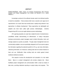
TO: ALL SOUTHBEND SERVICE REPRESENTATIVES AND PARTS DISTRIBUTORS
SUBJECT: INFRA RED BROILER - BROILER BURNER ORIFICE SIZING
Please insert m your master manual - BR Broiler- Cheese Melter Section.
Correct Infra Red Broiler Manual (170, 171D, 270) Part #1163089/1
Revised 5-89
Section 1 - Page 1
Orifice Size
Natural Gas
Rate
B.T.U.S. Hr 26.000
Propane Gas
26.000
#53
(.0595)
Section 4 - Page 1
Delete the following:
1163554
1163586
1164370
1166784
Add the following:
For Suffix "D”
1172601
1172602
1163653
For Suffix "A"
1117497
1117499
#41
(.0960)
Burner orifice assembly - Natural
Burner orifice assembly - Propane
Orifice spud - Natural No.36
Orifice spud - Propane No. 51
Burner orifice (Natural) #41
Burner orifice elbow
Burner orifice (Propane) #53
Orifice fitting (Natural)
Orifice fitting (Propane)
1100 Old Honeycutt Rd.
Fuquay-Varina, NC 27526
(919) 552-9161
FAX (919) 552-9798
AUTHORIZED PARTS DISTRIBUTORS & SERVICE AGENCIES
September 26, 1986
PILOT REPLACEMENT KIT FOR 170,171,270,171-40 INFRA RED BROILERS
Please insert in the BR-Broiler Section of your master Southbend Service Manual.
If one of the above models is experiencing pilot ignition problems, it is possible to
replace the Baso pilot with a Kinco 3 pilot system.
The kit you will need is:
Part No. A81-00008 Nat Gas - 3 pilot kit
Part No. A81-00009 LP Gas - 3 pilot kit
Current list price for each kit is $64.50.
These kits consist of: pilot support assy, pilot front panel, speed nut, and
installation instructions.
Patton G. Philotoff
Regional Service Manager
cc. Sales Directors
Sales Representatives
Internal Distribution
1100 Old Honeycutt Rd.
Fuquay-Varina, NC 27526
(919) 552-9161
FAX (919) 552-9798
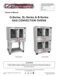
INFRA-RED BROILERS
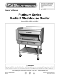
INSTALLATION
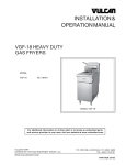
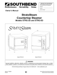
SPECIFICATIONS
Southbend Magic Ray Infra-Red Broiler
MODELS: 171-40A
171-40C
171-40D
Blower Switch
Warming
Oven
Broiler
Section
Rack Extends
18" Forward
When Pulled Out
1 ¼” NPT Manifold
For
Range Oven
Thermostatically
Controlled
ELECTRIC:
Supply, 115 VAC - 60 Hz - 15 AMP, by cord with 3-prong plug. Blower motor rated at 1.0 AMP for "A" suffix units,
and less than 1.0 AMP for "D" suffix units.
OPTIONAL:
Warming oven may be equipped with a 3000-watt element. This circuit has a separate 208/236 volt, single phase, 20
amp supply.
INFRA-RED BROILERS
SECTION ONE — INSTALLATION
PAGE 1
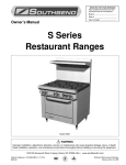
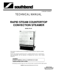
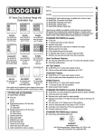
SPECIFICATIONS
MODELS 171-40A
171-40C
171-40D
TOP VIEW
FRONT VIEW
MODEL
BROILER
171-40A
171-40C
BROILER
171-400
OVEN
ALL
MODELS
GAS
TYPE
MANIFOLD
PRESSURE
Natural
BURNER
PILOT
RATE
BTUs/HR.
NO.
ORIFICE
SIZE
RATE
BTUs/HR.
NO.
ORIFICE
SIZE
4" W.C.
13,250
6
#51
(.067)
Approx.
800
3
Adjustable
Propane
10" W.C.
13,250
6
#59
(.041)
Approx.
800
3
Adjustable
Natural
4" W.C.
30,000
3
#36
(.1065)
Approx.
800
3
Adjustable
Propane
10" W.C.
30,000
3
#51
(.0670)
Approx.
800
3
Adjustable
Natural
6" W.C.
32,000
1
#42
(.0935)
Approx.
800
1
Adjustable
Propane
10" W.C.
32,000
1
#52
(.0635)
Approx.
800
1
Adjustable
INFRA-RED BROILERS
SECTION ONE — INSTALLATION
PAGE 2
Litho in U.S.A
8-88
INSTALLATION
GENERAL:
The installation must conform with local codes, or in the absence of local codes, with the National Fuel Gas Code, ANSI Z223.11984. In addition, units with Convection Oven Base must be electrically grounded and comply with local codes, or in the absence
of local codes, with the National Electrical Code ANSI NFPA 70-1984.
The appliance should be connected ONLY to the type of gas for which it is equipped. All Southbend equipment is adjusted at the
factory, however, burner air shutters and pilot heights should be checked at installation and adjusted if necessary. Check type of
gas on serial plate in the compartment below the oven.
For orifice sizes and pressure regulator settings, refer to the chart under "SPECIFICATIONS."
There are two (2) independent gas connections on this unit. A 3/4" NPT line supplies the broiler section and its connection is at
the rear, top left. The installer should use a 3/4" NPT service shutoff valve at this connection. The broiler section is equipped
with a pressure regulator which maintains a gas pressure of 4" W.C. for natural gas, and 10" W.C. for propane gas on the broiler
burner's manifold.
The 1 ¼” NPT manifold pipe running across the front of the unit supplies gas only to the lower thermostatically controlled oven.
Units can be batteried by joining the unions at the ends of the manifolds. This manifold is not equipped directly with a pressure
regulator. However, the manifold must be connected with an adequately-sized gas appliance pressure regulator adjusted to supply
a pressure to this manifold as marked on the serial plate; 6" W.C. for natural gas and 10" W.C. for propane gas. In addition, the
pressure regulator must meet the following requirements:
1. The pressure regulator installed should be certified by a recognized testing agency.
2. Unless the pilots are separately regulated, the regulator should be acceptable for total pilot load application.
3. The regulator must have a maximum regulation capacity for the total connected load.
4. The regulator must have a pressure adjustment range to allow adjustment to the manifold pressure on the appliance rating
plate.
5. Unless the manifold pressure of all connected appliances is the same, a separate regulator must be supplied for each unit(s)
to indicate unit or units having differing manifold pressures.
An adequate gas supply is imperative. Undersized or low pressure lines will restrict the volume of gas required for satisfactory
performance. A steady supply pressure, between 7" W.C. and 8" W.C. for natural gas and 11" W.C. and 12" W.C. for propane
gas, is recommended. With all units operating simultaneously, the manifold pressure on all units should not show any
appreciable drop. Fluctuations of more than 25% on natural gas and 10% on propane gas will create pilot problems and affect
burner operating characteristics. Contact your gas company for correct supply line sizes.
A 1/8" pressure tap for the oven is located on the 1 ¼” manifold.
A 1/8" pressure tap is located on each broiler manifold of the 171-40A and 171-40C,just behind the panel above the broiling
section. On 171-40D units, the 1/8" pressure tap is just after the pressure regulator at the right front, on top of the unit.
All pipe joints should be tested for leaks with a soap and water solution before operating the unit. The test pressure should not
exceed 14" W.C.
CAUTION: THIS APPLIANCE AND ITS INDIVIDUAL SHUTOFF VALVE MUST BE DISCONNECTED
FROM THE GAS SUPPLY PIPING SYSTEM DURING ANY PRESSURE TESTING OF THAT
SYSTEM AT TEST PRESSURES IN EXCESS OF 1/2 PSIG (3.45 kPa).
THIS APPLIANCE MUST BE ISOLATED FROM THE GAS SUPPIY PIPING SYSTEM BY
CLOSING ITS INDIVIDUAL MANUAL SHUTOFF VALVE DURING ANY PRESSURE TESTING
OF THE GAS SUPPLY PIPING SYSTEM AT TEST PRESSURES EQUAL TO OR LESS THAN
1/2 PSIG (3.45 kPa).
INFRA-RED BROILERS
SECTION ONE — INSTALLATION
PAGE 3
INSTALLATION
EXHAUST FANS AND CANOPIES:
Canopies are set over ranges, ovens, etc., for ventilation purposes. It is recommended that a canopy extend 6" past appliance
and be located 6' 6" from the floor. Filters should be installed at an angle of 45 degrees or more with the horizontal. This
prevents dripping grease and facilitates collecting the run-off grease in a drip pan, usually installed with a filter. A strong
exhaust fan tends to create a vacuum in the room and may interfere with burner performance or may extinguish pilot flames.
Fresh air openings approximately equal to the fan area will relieve such vacuum. In case of unsatisfactory performance on any
appliance, check with the exhaust fan in the "OFF" position.
WALL EXHAUST FAN: Should be installed at least 2 feet above the vent opening at the top of the shelf or backsplash.
All units must be installed in such a manner that the flow of combustion and ventilation air are not obstructed. Provisions for an
adequate air supply must also be provided. Do not obstruct the blower air intake duct at the lower rear of the unit, or the bottom
front just below the oven compartment, as combustion air enters through these areas.
NOTE: Due to the variety of problems encountered by outside weather conditions, venting by canopies or wall fans are
preferred over any type of direct venting.
Minimum clearances from combustible construction are:
6 INCHES FROM SIDES 6 INCHES FROM BACK 6 INCHES FROM FLOOR
No additional clearance from the sides and back is required for normal service, as the units are serviceable from the
front.
LEGS OR OPTIONAL CASTERS:
1. A set of legs or casters are packed in the unit. A threaded receptacle is fastened to the base frame at each
corner. Each leg or caster has a similar mating thread.
2. Raise unit sufficiently to allow legs or casters to be screwed into the receptacles. For safety, "shore up" and
support the unit with an adequate blocking arrangement strong enough to support the load.
3. Lower unit gently. Never drop or allow the unit to fall.
4. The legs or casters can be adjusted to overcome an uneven floor.
5. After the unit has been leveled, tighten the lock nuts.
WARNING:
FOR AN APPLIANCE EQUIPPED WITH CASTERS, THE INSTALLATION SHALL BE MADE
WITH A CONNECTOR THAT COMPLIES WITH THE STANDARD FOR CONNECTORS FOR
MOVABLE GAS APPLIANCES, ANSI Z21.69-1979, AND ADDENDA, Z21.69a.l983, AND A
QUICK-DISCONNECT DEVICE THAT COMPLIES WITH THE STANDARD FOR QUICKDISCONNECT DEVICES FOR USE WITH GAS FUEL, ANSI Z21.41-1978, AND ADDENDA,
Z21.41a-1981 AND Z21.41b.l983. ADEQUATE MEANS MUST BE PROVIDED TO LIMIT THE
MOVEMENT OF THE APPLIANCE WITHOUT DEPENDING ON THE CONNECTOR AND THE
QUICK-DISCONNECT DEVICE OR ITS ASSOCIATED PIPING TO LIMIT THE APPLIANCE
MOVEMENT.
WARNING:
IF DISCONNECTION OF THIS RESTRAINT IS NECESSARY TO MOVE THE APPLIANCE FOR
CLEANING, ETC., RECONNECT IT WHEN THE APPLIANCE IS MOVED TO ITS ORIGINALLY
INSTALLED POSITION.
INFRA-RED BROILERS
SECTION ONE — INSTALLATION
PAGE 4
Litho in US A
8-88
INSTALLATION
GAS CONNECTION:
A. BROILER SECTION:
1. Locate the 3/4" NPT threaded pipe nipple protruding from the upper left rear of the unit.
2. Connect gas supply to this nipple. Use pipe joint compound which is suitable for LP gas on all threaded connections.*
3. Check for gas leaks with a soapy water solution. NEVER USE AN OPEN FLAME.
*It is recommended that a main shutoff valve be provided outside the unit at the time of installation.
B. OVEN SECTION:
On all threaded connections the pipe joint compound must be approved for use with natural and LP gas.
I. INDIVIDUAL UNITS:
1. Remove valve panel.
2. Level the unit by adjusting the legs. Use a long spirit level on the racks and front top rail.
3. A. For units without a rear gas connection, connect the gas supply to the right or left side of the manifold. Be sure to cap
the unused side.
B. For units with a rear gas connection, the gas supply to the unit will be made at the right rear. Be certain both
ends of the manifold are capped.
4. Turn off all burner valves.
5. Turn on gas supply and immediately check all gas connections for leaks. Use soapy water only. Never use an open
flame.
6. Put valve panel back onto the unit.
II. ASSEMBLY OF BATTERY:
The units were aligned and fitted at the factory, from left to right as listed on the factory order, and must be installed in this
order to expect proper alignment and fit.
1. Position the center range of the battery and carefully level unit. Use a long spirit level four ways; across front top rail
and the rear collar plate, and along each edge.
2. Remove all valve panels. Mark, so they will be returned to their respective unit.
3. Bring up adjacent units, level by same method and by using the center unit as reference. Match front rails and rear
collar plates. When battery is set on a masonry base and legs are not used, shims may be used. Special attention
should be given to Fry Top ranges to allow proper drainage on griddles.
4. Where spreader plates are installed between units, the spreader plate should be secured to each adjacent unit at the
front by means of the 1 %" manifold and along the sides toward the rear, by bolts into top angles of the adjacent
units.
5. Connect units together by mating the unions. Make unions just HAND TIGHT at this time.
6. Starting at the center and working toward the ends, tighten each union gradually, going from one to another until all
are finally tight. A special thin wrench which fits the union nut is provided with each battery, or a chain wrench
can be used.
INFRA-RED BROILERS
SECTION ONE — INSTALLATION
PAGE 5
INSTALLATION
7. Connect gas supply at right, left, or both ends. When a Spreader Plate with a "Tee" connection is inserted in a
battery, the gas supply may be connected at this point. Ranges with rear connections may also be used in this
respect. If five or more units are batteried, more than one supply line should be used. Each supply line should
have a readily accessible, approved hand shutoff valve.
8. "Open" ends of the manifold must be capped.
9. Turn off all burner valves.
10. Turn on gas supply and immediately check all unions for leaks. USE SOAPY WATER ONLY FOR TESTING
ON ALL GASES. NEVER USE AN OPEN FLAME TO CHECK FOR GAS LEAKS.
11. When entire gas system has been proved, turn off gas supply during additional installation.
12. A filler to cover the "gap" between the range fronts is provided. They have been fitted, and holes were drilled
into the vertical members of the frames at the factory. They were marked and wrapped and are packed in the
ovens.
13. Place the filler over its respective "gap." Line up the predrilled holes and fasten with sheet metal screws.
14. Top filler strip — place over edge of side angle of adjacent range and secure to side of broiler to form a
sanitary seal between ranges.
WARNING:
TUBULAR GAS LINES ARE LOCATED ON THE LEFT SIDE OF THE STANDARD OVEN BASE
UNITS BEHIND THE FILLER SECURING SCREW AREA. IF HOLES NEED TO BE DRILLED,
CARE MUST BE TAKEN AND INSPECTION MADE TO INSURE GAS LINES ARE NOT
PUNCTURED.
ELECTRICAL CONNECTION:
The standard electrical equipment is for a 115 VAC, 60 cycle, 15 AMP single phase system and is supplied by a
cord set with a third wire ground and a three-prong plug which fits any standard 115V, three-prong grounded
receptacle. The blower is powered by a 1/40 HP motor, using 1 AMP, on "A" suffix models (see Diagram 3) and a
1/80 HP motor, using less than 1 AMP on "D" suffix models (see Diagram 2). Location of diagram will be attached
near the blower motor.
WARNING:
THE THREE-PRONG (GROUNDING) PLUG IS SUPPLIED FOR YOUR PROTECTION
AGAINST SHOCK HAZARD AND MUST BE ELECTRICALLY GROUNDED IN ACCORDANCE
WITH LOCAL CODES, OR IN THE ABSENCE OF LOCAL CODES, WITH THE NATIONAL
ELECTRICAL CODE, ANSI/NFPA 70-1984. DO NOT CUT OR REMOVE THE GROUNDING
PRONG FROM THIS PLUG.
An optional electric element rated at 3,000 watt, 208/236 volts, is available in the warming oven. This is indicated
on the serial plate by the prefix EW. A separate electric supply, 208/236V, single phase, 20 AMP, must be
connected to the leads in a terminal box at the rear, near the top of the broiler (see Diagram 1). Diagram will be on
rear of unit near the top of the broiler. This installation must conform with local codes, or in their absence, with the
National Electrical Code ANSI/NFPA 70-1984.
INFRA-RED BROILERS
SECTION ONE — INSTALLATION
PAGE 6
Litho in U.S.A.
8-88
OPERATION
INITIAL OPERATION CHECK: (Broiling Section)
The suffix "A" indicates that a centrifugal switch within the motor controls a gas solenoid. The unit cannot be operated without
power to the unit.
The suffix "D" indicates that there is no centrifugal switch or gas solenoid valve. These units employ the Southbend exclusive
burners which can operate with or without the blower. For optimum performance, however, the blower should be used:
I. When all gas and electrical connections have been checked out, proceed as follows to put the unit into operation:
A. Turn broiler burner valves to OFF.
B. Turn blower switch to OFF.
C. Turn on the main gas supply.
D. Turn on manual service valve located in inlet supply line in the blower compartment.
E. Suffix "A" models have a pair of burners and each has a pilot at its front. Light these 3 pilots. These pilots are
controlled by a small valve located behind the plug button, just below the left burner valve. The pilot flame should be
3/4" high; adjust if necessary.
F. For suffix "D" models, each burner has a pilot at its front. Light these 3 pilots. These pilots are controlled by a small
valve located behind the plug button. This button will be located in the very center at the top of the unit. The pilot
flame should be 3/4" high; adjust if necessary.
These pilots should burn continuously unless the broiler is to be completely shut down. When extinguished, the pilot gas
supply is NOT INTERRUPTED automatically. For complete shut down, the large manual service valve on the inlet gas
supply line, referred to in I-D above, must be turned to "OFF."
II. Press the blower switch to "ON."
A. For "A" suffix units:
1. The motor (blower) will start.
2. As it accelerates, its centrifugal switch will close.
3. This allows current to flow to the gas solenoid and the indicator light.
4. When the gas solenoid is energized, it opens, allowing gas to flow to the main burner valves.
5. When the red light glows, it indicates that the gas solenoid is "OPEN."
B. For "D" suffix units:
1. The motor (blower) and red indicator light will be energized immediately. The electrical circuitry does not
control the gas.
2. Gas is always available to the main valves, even with the motor off.
NOTE: Should an odor of gas be detected, check for leaks on all fittings within the blower compartment, using the
soapy water method. NEVER USE AN OPEN FLAME.
III. Turn the broiler burner valves to HIGH. As each valve is opened, immediately check ignition of burners.
When the burners ignite, a blue flame will cover the surface of the ceramics for 10-15 seconds. This haze will disappear
and within 30 seconds the ceramics will glow red. The flame on the surface of the ceramics should be barely visible, with
practically no blue haze. Should this condition not be obtained, ti may be necessary to regulate the air supply to the
manifold compartment. This air is supplied by a blower, with a shutter for regulation. There is NO primary air adjustment
on the burner itself (see ADJUSTMENTS).
INFRA-RED BROILERS
SECTION TWO — USER'S GUIDE
PAGE 2
Litho in U.S A.
8-88
OPERATION
IV. After the burners have operated properly on HIGH for several minutes, turn the valve to LO. The surface of the
ceramics on the burner should become a very dull red, with a slight blue haze. The burners should NOT flutter
or "POP" under these conditions. For regulation of the LO setting, refer to this item under ADJUSTMENTS.
V. UNIT WITH WARMING OVEN ABOVE THE BROILING SECTION:
As an option, an electric element can be installed in this oven at the factory.
To check element, turn switch above warming oven door to ON. Element should become dull red in a few
minutes.
DAILY OPERATION: (Broiling Section)
Put the broiler into operation by the following procedure:
1. The pilots should have remained ignited from the installation initial checkout, howe ver, it is good practice to
always check if they are burning before proceeding.
2. Press the blower switch to ON.
3. Turn the broiler burner valve on the section desired for use to HIGH.
CAUTION: FOR SAFETY REASONS, THE BROILER BURNERS SHOULD BE VISUALLY OBSERVED
FOR PROPER IGNITION EACH TIME UNIT IS PLACED IN OPERATION. THIS SAFETY
CONSIDERATION SHOULD BE OBSERVED FOR ALL OVER-FIRED BROILERS. SHOULD
IGNITION FAIL AFTER 5 SECONDS, TURN BROILER VALVE OFF AND WAITS MINUTES
BEFORE TRYING AGAIN.
4. When the burners ignite, a blue flame will cover the surface of the ceramics for 10-15 seconds. This haze will
disappear and within 30 seconds the ceramics will glow red. The flame on the surface of the ceramics should be
barely visible, with practically no blue haze.
5. Put the broiler rack at its highest position and allow the burners to operate for five minutes.
6. The broiler is now ready for use. For best results, follow techniques
under COOKING HINTS.
NOTE: The front 3" of the broiler rack may be used as a holding area.
This holding area is marked by a 1/8" dia. rod as shown — see
Fig. 9.
TO CONSERVE GAS ENERGY: The "LO" setting can be used to
advantage during slack periods between broiling operations; when
turned back to "HI," the ceramics will change to a bright red within
seconds and be ready for fast broiling. During this down period, bring
the broiling rack to its highest position. This method will keep it hot and
the rack will be "ready" to sear and "mark" the steaks without additional
preheating.
Each broiler section is controlled by two valves.
A. On "A" suffix units, the right valve controls the three burners on the right and the left valve the three on the
left.
B. On "D" suffix units, the right valve controls the two burners on the right and the left valve the extreme left
burner only.
Use only as many burners as required to conserve energy.
INFRA-RED BROILERS
SECTION TWO - USER'S GUIDE
PAGE 3
OPERATION
WARMING OVEN:
The oven is heated by the flue products from the broiler. To operate the broiler burners just to heat the oven, when
the broiler is not in operation, is inefficient and not recommended. When the optional electric element is installed in
this oven, it can be used when the broiler is not operating, or to increase the temperature of this oven when the
broiler burners are operating. There is no thermostat to regulate this oven temperature. The only control is the ON
and OFF switch.
POWER FAILURE:
In the event of an electric power failure, no attempt should be made to operate those units with an "A" suffix. Turn
off all gas and the blower switch until power is restored. Units with a "D" suffix will operate during power failures.
OVEN: (Ovens on all models are identical)
1. Open door, raise hold-down clips, and remove oven bottom so burner is visible.
2. Turn oven burner to OFF.
3. Remove panel from spring compartment below oven door.
4. Depress RED button on safety valve and light pilot. New installations may require time to bleed air from
system before pilot will become steady. The pilot flame should impinge on the bulb to cause it to glow red. If
flame is too long and soft, bulb may be in "hollow" part of flame and will not glow.
5. Hold RED button, allowing pilot to burn approximately 45 seconds, until tip of bulb glows red and then release
button.
If pilot does not remain ignited, wait 5 minutes and repeat procedure.
6. Once pilot holds when button is released, set thermostat dial to maximum and turn ON the oven valve at
manifold.
7. Burner flames should be 3/4" to 1" long. Adjust if necessary.
8. Reduce thermostat setting slowly until bypass seat in thermostat just snaps OFF.
Immediately reverse rotation and turn dial counterclockwise until bypass snaps open.
The bypass flame should be 1/8" minimum and 1/4" maximum on each port.
A small fluttering bypass flame may flash back into the burner and ignite on the orifice when the door is
quickly opened or closed. This will create a c arbon deposit inside the burners which impedes proper primary air
injection. See section on bypass flame adjustment.
9. Check entire oven gas system for leaks.
10. Replace oven bottom and be sure hold-down clips are lowered to keep bottom in place and prevent warping.
OVEN SHUT DOWN:
Daily:
Turn main oven gas valve to "OFF" position.
Complete Shut Down:
Turn main oven gas valve to "OFF" position and extinguish oven pilot.
INFRA-RED BROILERS
SECTION TWO — USER'S GUIDE
PAGE 4
Litho in U.S.A.
8-88
COOKING HINTS
Due to the speed of this infra-red broiler, broiling times will be reduced and techniques may require some modification.
For most broiling of steaks, chops, etc., the burners should be operated on "HI" and the degree of internal rareness and surface
condition can be controlled by raising and lowering the rack mechanism. For products such as fish or fowl, where the product
must be broiled thoroughly, the flame may be reduced and rack position lowered to prevent charring the skin surface.
INFRA-RED BROILING GUIDE
Broiling Time — Minutes
Namp No.
180
180
180
190
412
232
184
Type Product
Strip Loin Steak (Ctr. Cut)
Strip Loin Steak (Ctr. Cut)
Strip Loin Steak (Ctr. Cut)
Beef Tenderloin (Ctr. Cut)
Pork Chop
Lamb Chop
Butt Steak (End Cut)
Lobster Tail (Preboiled)
Ground Chuck Steak Patty
Ground Chuck Steak Patty
Meat Valve **Rack
Med. Mod.
Thickness
Weight Temp Setting Pos.
Rare Rare Med. Well Well
.
1 ½”
16 oz.
40°
High
2(d)
4
6½
9
10 ½ 11½
1 ½”
16 02.
40°
High
3(d)
4½
7
9½
11
12
3/4"
1202.
40°
High
3(d)
3
5
6¼
7
—
2"
8 oz.
40°
High
3(d)
5½
8
10
12
14
1"
8 oz.
70°
High
3(d)
—
—
—
—
9
1 ¼”
7oz.
70°
High
3(d)
—
5½
—
8
1"
10 oz.
70°
High
3(d)
2½ 4½
6
7
7¾
—
10 oz.
70°
High
3(d)
—
—
—
—
2½
(Approx.1/2")
4 oz.
70°
High
2(d)
—
5
7
8
—
(Approx. 1")
8 oz.
70°
High
2(d)
—
6
8
10
—
**2(d) — 2nd down
3(d) — 3rd down
DONENESS OF STEAK WAS BASED AS FOLLOWS:
RARE — Deep Red Center MEDIUM RARE — Red Center MEDIUM — Deep Pink Center
MEDIUM WELL - Light Pink Center
WELL - Brown Center
FISH — Burners on low setting, grid in low position, place fish on a pan approximately 5 or more minutes,
according to kind and thickness of fish.
CHICKEN HALVES OR QUARTERS — Burners on low setting, grid in low position, approximately 12 to 14
minutes bone side up, approximately 5 minutes skin side up according to size.
THIS IS INTENDED AS A GUIDE. TEMPERATURE OF MEAT, SIZE OF PORTION, LOAD IN BROILER,
DEGREE OF DONENESS, OR OTHER VARIABLES WILL DETERMINE THE BROILING PROCEDURE.
INFRA-RED BROILERS SECTION
TWO — USER'S GUIDE
PAGE 5
MAINTENANCE
WARNING:
ALL ADJUSTING AND SERVICE SHOULD BE PERFORMED BY A PERSON KNOWLEDGEABLE IN
MAKING SUCH ADJUSTMENTS. IF IN DOUBT - CALL YOUR AUTHORIZED SERVICE AGENCY.
Southbend equipment is sturdily constructed of the best quality materials and is designed to provide durable service when
treated with ordinary care. To expect the best performance, your equipment must be maintained in good condition and cleaned
daily. Naturally, the periods for this care and cleaning depend on the amount and degree of usage.
Following daily and periodic maintenance procedures will enhance long-life for your equipment. Climatic conditions
— salt air — may require more thorough and frequent cleaning, or the life of the equipment could be adversely
affected.
MAINTENANCE:
1. Keep exposed, cleanable areas of unit clean at all times.
Daily:
A. Remove, empty and clean grease drawees).
B. Thoroughly wash grease hopper below rack.
C. Thoroughly wash rack.
D. Clean warming oven.
Monthly:
A. Clean around oven burner air mixer and orifice if lint has accumulated.
B. Visually assure proper pilot operation.
C. Lubricate valves.
Vent System:
At least twice a year the unit venting system should be examined and cleaned.
STAINLESS STEEL:
1. To remove normal dirt, grease and product residue from stainless steel that operates at LOW temperature, use ordinary soap
and water (with or without detergent) applied with a sponge or cloth. Dry thoroughly with a clean cloth.
2. To remove grease and food splatter or condensed vapors that have BAKED on the equipment, apply cleanser to a damp
cloth or sponge and rub cleanser on the metal in the direction of the polishing lines on the metal. Rubbing cleanser as
gently as possible in the direction of the polished lines will not mar the finish of the stainless steel. NEVER RUB WITH A
CIRCULAR MOTION. Soil and burnt deposits which do not respond to the above procedure can usually be removed by
rubbing the surface with SCOTCH-BRITE scouring pads or STAINLESS scouring pads. DO NOT USE ORDINARY
STEEL WOOL, as any particles left on the surface will rust and further spoil the appearance of the finish. NEVER USE A
WIRE BRUSH, STEEL SCOURING PADS (EXCEPT STAINLESS), SCRAPER, FILE OR OTHER STEEL TOOLS.
Surfaces which are marred collect dirt more rapidly and become more difficult to clean. Marring also increases the
possibility of corrosive attack. Refinishing may then be required.
3. To remove heat tint: Darkened areas sometimes appear on stainless steel surfaces where the area has been subjected to
excessive heat. These darkened areas are caused by thickening of the protective surface of the stainless steel and are not
harmful. Heat tint can normally be removed by the foregoing, but tint which does not respond to this procedure calls for
vigorous scouring in the direction of the polish lines using SCOTCH-BRITE scouring pads, or a STAINLESS scouring
pad, in combination with a powdered cleanser. Heat tint action may be lessened by not applying, or by reducing, heat to
unit during slack periods.
INFRA-RED BROILERS
SECTION TWO — USER'S GUIDE
PAGE 6
Litho in U.S.A.
8-88
MAINTENANCE
BLACK BAKED ENAMEL:
1. Allow unit to cool somewhat after use and wash exterior with a hot, mild detergent or soap solution; particularly clean off all
grease deposits. Dry thoroughly with a dry cloth.
BROILING SECTION:
To prevent excess smoking, the grids, rack drip pan and the other members must be kept clean of food remnants. Use wire brush
or similar scraping utensil. DO NOT use steel wool or similar scrub pad that will leave small metal particles which can get into
food.
TO CLEAN:
1. Put rack in lower position. Pull out rolling rack.
2. Lift out broiler grid and clean with wire brush or non-toxic solvent.
3. Remove rack pan and clean.
4. With rolling rack pulled out to its "stop," raise front with handle so its rollers will come through the notches in the raising and
lowering frame. Clean all parts where residue collects.
5. Clean all parts of the raising and lowering frame.
6. Clean entire hopper section of all caked grease and residue.
7. Lubricate bearings with cooking oil.
8. Reverse procedure to reassemble broiling rack mechanism.
MODEL WITH WARMING OVEN:
Any accumulation of grease allowed to remain in this oven area eventually becomes a fire hazard. As a preventative measure it must
be cleaned DAILY.
TO CLEAN:
1. Remove the perforated bottom and wash with a solution of hot water and a strong detergent or any other non-toxic grease cutting
solvent.
2. Wipe the side, rear and top linings with the same solution.
3. Rinse with clear hot water.
4. Take care that any grease which may have collected in the flue vent collar is also removed.
5. Put oven bottom back in position.
OVEN INTERIOR: Allow oven to cool. Remove oven racks and porcelain enameled oven bottom. Clean by rubbing with
strong detergent and BRILLO pad or similar scrubber. "Spill-over" should be cleaned from the bottom as soon as possible to
prevent carbonizing and a burnt-on condition. For stubborn accumulations, commercial oven cleaners are recommended.
The porcelain oven door lining can be cleaned in a similar manner.
The side, rear and top lining should be wiped only with a cloth dampened with a mild detergent and water. Avoid using
excessive amounts of water, as it may drip into burner compartment and deteriorate the metal in that area.
Do not use strong commercial cleansers or abrasive pads on these sides, back or top linings, as they may damage the finish or leave
gray residue.
INFRA-RED BROILERS
SECTION TWO — USER'S GUIDE
PAGE 7
INFRA-RED BROILERS
SERVICE
ADJUSTMENTS
AT LEAST TWICE A YEAR HAVE YOUR SOUTHBEND AUTHORIZED SERVICE AGENCY
CLEAN AND ADJUST THE UNIT FOR MAXIMUM PERFORMANCE.
In case of problems in operation at initial installation, check type of gas and manifold pressure and compare with
information listed on the serial plate, located at the left front corner of the body top.
BROILER:
PILOT VALVE LOCATIONS: There is a single adjustment behind the hole at the center of the perforated panel above
the warming oven.
Adjustment to pilots id made by turning the small slotted screw on the pilot valve. The flame on each pilot should be
approximately 3/4" high.
LOW SETTING: The LO adjustment of the broiler burner valves is by a set screw in the hollow stem of this valve.
Turn "IN," or clockwise, to reduce and "OUT," or counterclockwise, to increase. Burner flame on low setting should
not flutter or "POP," but should burn with a dull red and a blue haze.
AIR ADJUSTMENT: In the blower area, above the warming oven, the blower inlet is against a large air supply
duct. The blower is pulling air through a 5 ½” diameter hole in this duct. A sliding gate regulates the amount of air
pulled through this opening. By loosening a set screw, this gate can be moved to restrict the air supply to the
burners.
If the flame is blowing away from the burner there is an excess of air. Close the air shutter on the blower until the flame
stabilizes. Adjust for brightest glow without blue haze or blowing.
The screen on the blower intake may be clogged with lint. Use vacuum cleaner attachment to clean.
PRESSURE REGULATOR:
1. Locate 1/8" pressure tap.
A. For units with the "A" suffix, a 1/8" pressure tap is located on each of the two burner manifolds. These
manifolds are located behind the stainless steel panel above each broiling section. Remove the two screws
securing it. A second panel will be found behind the first. Remove the six screws securing it and remove the
second panel. The manifolds should now be visible.
B. For units with "D" suffix, the 1/8" pressure tap is located along the front top edge of the unit, just past the
pressure regulator.
2. Turn "OFF" main gas supply to unit and all valves.
3. Remove the 1/8" pipe plug and install a fitting appropriate for the connection of a manometer.
4. Connect the manometer.
5. Turn main gas "ON."
6. Light all pilots.
7. Turn all burners to full on.
8. Read manometer.
A. For all units Broiler Section, the manometer should read 4" W.C. for natural gas and 10" W.C. for propane
gas.
INFRA-RED BROILERS
SECTION THREE — SERVICE
PAGE 1
ADJUSTMENTS
9. If manometer reads correctly, go to Step 13.
10. If manometer shows incorrect reading, remove cap from top of regulator.
11. With a screwdriver, rotate regulator adjustment screw "clockwise" to increase or "counter-clockwise" to decrease pressure
until manometer shows correct reading.
12. Put cap on regulator.
13. Turn all burner valves "OFF."
14. Turn main gas "OFF."
15. Remove manometer fitting.
16. Replace plug in manifold.
17. Replace panels ("A" suffix units) or filter ("D" suffix units).
18. Turn main gas "ON."
19. Light all pilots.
OVEN:
PILOT: Take off lower front panel below oven by removing the two screws which secure it. Turn slotted screw adjacent to red
button on safety. Minimum pilot (approximately 3/4" long) should withstand a quick opening and closing of the oven door.
BURNER:
1. Obtain access to burner air shutter by removing the lower front panel below the oven. It is secured by two screws.
2. Turn valve or thermostat to FULL ON position.
3. Loosen the screw which holds the air shutter.
4. If flame is blowing or lifting off of the ports, close air shutter on front of burner until a stable flame is obtained.
5. If the flame is yellow tipping, open the air shutter until a stable flame is obtained.
6. Tighten the screw which holds the air shutter.
7. Replace the oven panel.
OVEN BYPASS FLAME (MINIMUM BURNER FLAME) ADJUSTMENT:
The pilot must be lit to make this adjustment.
1. Remove oven bottom so burner is visible.
2. Turn on oven valve.
3. Turn thermostat to 200 °F so main burner ignites.
4. With oven cool, turn dial clockwise slowly until bypass seat just snaps OFF.
5. Immediately reverse rotation and turn dial counterclockwise until bypass snaps open.
6. Remove dial.
7. With a screwdriver, turn "bypass flame adjuster" screw counterclockwise to increase the bypass flame or clockwise to
decrease the entire burner to a 1/8" minimum — 1/4" maximum stable flame. (See Fig. 1, Section 3, Page 3)
8. Replace dial.
NOTE: While making this adjustment, if the oven should become heated while the dial is set at a low range (below 350°F), the
bypass flame will shut off completely. If this occurs, turn dial counterclockwise slowly, until bypass gas snaps on. Then check
bypass adjustment as stated above.
INFRA-RED BROILERS
SECTION THREE — SERVICE
PAGE 2
Litho in U.S.A.
8-88
ADJUSTMENTS
RECALIBRATION:
Oven Thermostat
Field recalibration is seldom necessary and should not be resorted to unless experience with cooking results definitely
proves that the control is not maintaining the temperature to which the dial is set. To check oven temperatures when
recalibrating, use a thermocouple temperature test instrument, or a reliable mercury thermometer.
1. Place the thermocouple of test instrument or thermometer in the middle of an empty oven.
2. Remove knob. Use indicator mark as shown in Fig. 1 for all dial settings.
3. Turn thermostat so 400° F lines up with the indicator mark.
4. Allow the oven to heat until flame cuts down to bypass. After sufficient time, check temperature. If the temperature
does not read within 15 degrees of the dial setting, recalibrate as follows:
5. Hold calibration plate and loosen the two calibration lock screws until the plate can be moved independently of the
control.
6. Turn calibration plate so that the instrument or thermometer reading is in line with the indicator mark, as explained
above. Tighten the lock screws. Replace dial.
7. NOTE: If the above adjustment is prevented by the two loosened calibration lock screws being in contact with the
ends of the screw clearance slots in the calibration plate, remove the screws and after turning the calibration plate to
the proper location, reassemble screws in the other tapped holes designed for them.
Fig. 1
INFRA-RED BROILERS
SECTION THREE — SERVICE
PAGE 3
ADJUSTMENTS
TROUBLE SHOOTING: (Oven Section)
Problem
Look for —
All ranges in battery will
— Main gas supply to ranges is "OFF."
not turn on
All ranges produce excessive
— Incorrect gas type supplied to battery.
carbon deposits
— Incorrect supply pressure.
Only some ranges in a battery
— Incorrect orifices.
produce excessive carbon
— Primary air not adjusted properly.
deposits (burners)
Only some pilots produce
— Pilot gas not adjusted properly.
excessive carbon deposits
— Incorrect pilot orifice.
Oven will not come on
— Manual valve for oven in "OFF" position.
— Oven pilot is out.
Oven pilot will not stay ignited
— Pilot gas not adjusted properly.
— Bad thermocouple.
— Bad thermocouple connections at safety valve.
— Bad safety.
— Clogged orifice.
— Draft condition.
— Improper ventilation system.
— Air in gas line.
Top section pilot will not
stay ignited
— Pilot gas not adjusted properly.
— Clogged orifice.
— Draft condition.
— Improper ventilation system.
— Air in gas line.
INFRA-RED BROILERS
SECTION THREE — SERVICE
PAGE 4
Litho in U.S.A.
8-88
ADJUSTMENTS
TROUBLE SHOOTING: (Broiler Section)
Problem
Look for —
Not enough heat
— Restriction in valve.
— Restriction in gas supply.
— Misalignment of orifice tube.
— Clogged orifice.
— Incorrect orifice.
— Low pressure on gas supply.
— Incorrect gas.
Burner with blue haze
— Misalignment of orifice tube.
— Low gas pressure.
— Blocked primary air, exhaust gases blocked by objects
setting on top of broiler.
— Blower not functioning correctly.
Burner fluttering
— Adjust valve on low setting.
Burner popping
— Cracked or loose ceramic.
Too much heat
— Incorrect orifices.
— Defective or incorrectly set pressure regulator.
— Incorrect gas.
Slow burner ignition
— Check for proper pilot flame length.
— Check for proper pilot alignment.
— Clean pilot orifice.
Pilot outage
— Clogged orifice.
— Draft condition.
Incorrect orifice.
— Adjustment.
— Air in gas line.
No gas to burner
— Gas supply is turned off.
— Defective solenoid valve (suffix "A" units).
— Loose connection within wire nuts (suffix "A" units).
— Defective switch (suffix "A" units).
INFRA-RED BROILERS
SECTION THREE - SERVICE
PAGE 5
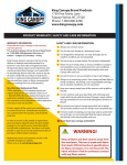
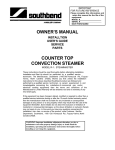
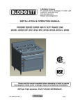
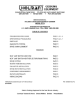
SERVICE
208/240 VAC
20 AMPS—1 PHASE SUPPLY
DPST SWITCH S-11
3000W WARMING ELEMENT
SOUTHBEND
WIRING DIAGRAM
WARMING OVEN ELEMENT - OPTIONAL
DWG. NO. SE-1353
INFRA-RED BROILERS
SECTION THREE – SERVICE
PAGE 6
Litho in U.S.A
8-88
SERVICE
INFRA-RED BROILERS
SECTION THREE – SERVICE
PAGE 7
SERVICE
INFRA-RED BROILERS
SECTION THREE – SERVICE
PAGE 8
Litho in U.S.A
8-88
INFRA-RED BROILERS
PARTS
PARTS
REPLACEMENT PARTS LIST
The serial plate is located inside the lower front panel on the right. When ordering parts from the Southbend Parts Distributor,
please supply them with the Model Number, Serial Number, Part Number, Description, plus Finish and/or Type of Gas if
applicable.
For parts not listed, consult a Southbend Parts Distributor or Authorized Service Agency. If necessary, please consult Southbend
Parts Department for assistance.
2
2
1
1
—
1
2
2
1
1
1
2
1
1
2
1
1
1
1
3
3
3
4
4
1
3
3
3
3
3
1
1
1
1
2
1
1
1
—
1
1
1
1
1
—
—
—
—
1062659
1117499
1163875
1069600
P7139
1146210
1111093
1110192
4275
4276
600 Lt.
600 Rt.
4258
4257
624
1010398
1010301
1114099
1164037
1161033
1046407
1161034
1046408
1163869
1163870
1163917
1141800
1164125
1099099
1163844
1021300
1160533
1008742
1008752
1000315
1118199
1024195
1024194
4440000
2537
P1089
1119099
1119000
1034900
1034901
1163868
1167004
171-40D
Roller Bearing (Front)
Inner Rack Frame Assy.
Index Plate
Outer Rack Frame Assy.
Broiler Grid Rack
Rack Pan
Grease Drain Assy. (420)
Plug Button
Pressure Regulator (Natural)
Pressure Regulator (Propane)
Roll. Rack or Oven Door Handle
Name Plate
Broiler Pilot (Natural)
Broiler Pilot (Propane)
Pilot Shield
Legs (Plated)
Legs (Black) (1034102)
Blower Motor (1164076)
Burner Assy.
Burner Orifice Assy. (Natural)
Burner Orifice Assy. (Propane)
Orifice Spud M3 (Natural)
Orifice Spud f53 (Propane)
Pilot Valve
Grease Drawer Assy.
Grease Drawer Front (S.S.)
Grease Drawer Front (Black)
Rack Tension Spring
Cabinet Pull Handles
Blower Switch
Solenoid Valve
Coil for
Indicator Light
Adhesive "ON" Label
Supply Cord
Blower-Motor
Blower Air Adjust. Disc.
Ray Head Burner Assy. (Natural)
Burner Orifice Spud #50 (Natural)
Orifice Ext. Fitting (Natural)
Ray Head Burner Assy. (Propane)
2
2
1
1
1
1
2
2
1
1
1
2
1
1
2
1
1
1
1
3
3
3
4
4
1
3
3
3
3
3
1
1
1
1
2
1
1
—
1
1
1
1
—
1
3
6
6
3
PART
NO.
171-40A
171-40C
1161450
1163054
1162951
1162955
1162956
1117199
1062650
1117497
1117198
Broiler Valve HI-LO
Valve Knob HI-LO
Mechanism Handle Knob
Mechanism Handle Assy.
Pilot Valve and Filter Assy.
Manual Service Valve
Roller Bearing (Rear)
QUANTITY
171-40D
1076799
1073498
15962
1061497
1099099
12864
4440005
4440006
427
1106814
432
1119598
1116699
1143099
12476
1160164
1160173
4440000
1017200
1160410
1161308
1162824
1034103
1034111
1164095
1163875
1164369
1163586
1164370
1163653
P2133
4277SS
1025901
1025900
1060500
4440009
1011815
1163503
DESCRIPTION
171-40C
PART
NO.
171-40A
QUANTITY
Burner Orifice Spud #59 (Propane)
Orifice Ext. Fitting (Propane)
Ray Head Burner (Nat. or LP)
Radiant Screens
Burner Support Bar (Rear)
Brns. Frt. Sup. Bolt
5/16 x 18 x 1 ½
Flue Deflector (S.S.)
6
6
—
—
—
—
3
33
6
—
1
6
1
Flue Deflector (Black)
Warming Oven Ooor Assy. (Black) (1164379)
Warming Oven Door Assy. (S.S.) (1164380)
Warming Oven Door Wt. Assy. Lt.
Warming Oven Door Wt. Assy. Rt.
Warming Oven Door Sprt. Assy. Lt.
Warming Oven Door Sprt. Assy. Rt.
Warming Oven Bottom
Thermostat & Dial
Dial for 1010398
Oven Safety
Oven Safety
Pilot Assy. (Natural)
Orifice for 1161033 (.017)
Pilot Assy. (Propane)
Orifice for 1161034 (.009)
Pilot Assy. (Natural)
Orifice for 1163869 ( )
Pilot Assy. (Propane)
Orifice for 1163870 (.010)
Oven Burner Assy.
Oven Burner
Pilot Filter & Valve
Oven Pilot Filter
Oven Valve
Oven Valve Knob
Oven Orifice 042 (Natural)
Oven Orifice H52 (Propane)
Oven Rack
Oven Bottom & Baffle Assy.
Oven Door Assy. (Black)
Oven Door Assy. (S.S.)
Oven Door Handle w/Screws
Door Hinge Assy.
Oven Door Spring
Quadrant Bracket Assy.
Quadrant Only
Lt. Spring Hook
Rt. Spring Hook
Thermocouple
Oven Fire Plate for Units produced after 7-84
1
1
1
1
1
1
1
1
1
1
1
—
1
1
1
1
—
—
—
—
1
—
1
—
1
1
1
1
1
1
1
1
1
2
2
2
2
1
1
—
—
1
1
1
1
1
1
1
1
1
1
—
1
—
—
—
—
1
1
1
1
—
1
—
1
1
1
1
1
1
1
1
1
1
2
2
2
2
1
1
1
1
DESCRIPTION
INFRA-RED BROILERS
SECTION FOUR — PARTS
PAGE 1