1
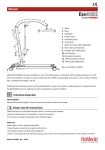
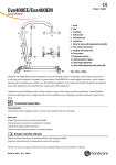
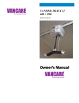
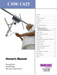
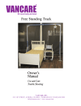
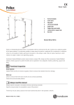
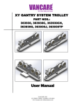
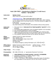
Manual - English
1
11
1. Boom
9
3
2. Mast
2
3. Handlebar
4. Battery pack
5. Emergency stop
6. Control box
7. Motor for base-width adjustment
4
8. Rear castors with brakes
12
9. SlingBar with safety latch
5
6
10. Front castors
11. Emergency lowering
12. Motor/actuator for boom
7
13. Mast height adjustment
13
Max. load: 205 kg / 450Ibs
10
8
Mobile lift Eva450EE has been developed to meet most lifting needs in combination with the right accessories. It is a lift
that can lift patients in a seated or supine position.The Eva450EE is made largely of aluminium, which makes it relatively
light,
considering
the weighthas
it can
lift. developed to meet most lifting needs in combination with the right
VanGo
VG400/VG450
been
accessories. It is a lift that can lift patients in a seated or supine position. The VanGo is made largely
Handicare’s
SystemRoMedic
product
series includes
a range of lifts,
anditother
SystemRoMedic
of aluminum,
which makes
it relatively
light, considering
theslings
weight
can accessories.
lift.
adopts a holistic approach to patient transfers and is organized in four categories: transfer, positioning, support and
lifting.
Functional inspection
Visual inspection
Inspect lift functions regularly. Check to ensure that material is free from damage.
Before use:
Ensure that the product is correctly assembled.
Check slingbar connection and safety latch function.
Check lift and base-width movement.
Check to ensure that the actuator is correctly installed.
Always read the manual
Always read the manuals for all assistive devices used during a transfer.
Keep the manual where it is accessible to users of the product.
The lift may only be used by persons who have received instruction in the operation of the lift.
Manual nr: 00789En Ver. 2 110203
Table of contents
Assembly. ......................................................................................... 3
- Final inspection...................................................................................... 4
Using the product.......................................................................... 5
- Important information ............................................................................ 5
- Safe working load.................................................................................. 5
- Charging batteries.................................................................................. 6
- Handset................................................................................................. 6
- Emergency stop..................................................................................... 7
- Emergency lowering............................................................................... 7
- Trouble shooting..................................................................................... 7
Accessories.....................................................................................
8
Maintenance.................................................................................... 9
Technical information.................................................................10
- Dimensions Eva450EE.......................................................................11-12
2
MANUAL
Assembly
Check to ensure that all components are included:
Mast with boom, lift motor, carry bar, control box and battery pack.
Base with motor and locking handle. Handset and cord.
Instructions, charging cable and power supply cord for charging.
Place the mast in the base. There are three alternatives for adjusting the height of the
mast. Secure the mast with the locking handle.
Place the battery in the mount in the control box.
Mount handlebar with two wrenches.
Connect the cables: The cable for the handset in outlet HS; the cable for the hoist motor
in outlet M1, and the cable for the base motor in outlet M2.
Release the emergency stop and perform a final inspection (see final inspection).
HS
M1
M2
MANUAL
3
Final inspection
Check to ensure that no parts have been left in the packaging.
Inspect the lift for signs of wear and damage.
Check all four castor wheels and castor wheel locks.
Check all connections and fixtures including screws and bolts.
Check the emergency stop function by depressing the emergency stop, and then
pressing either the up or down button. If nothing happens when the up or down
buttons are pressed, the emergency stop is functioning properly.
Grasp the handset, press the up button and run the lift arm all the way up. Then, press
the down button and run the lift arm all the way down.
Test base-width adjustment function. Press the button for base-width adjustment to
widen the base fully, and then press the other button to narrow the base again.
Test lift function by lifting a person (not a patient) using an approved sling. At the same
time, check the emergency lowering function with someone on the lift. See section on
Emergency lowering.
If the lift is functioning correctly, connect the charger and check to ensure that the
charging lamp on the control box lights up.
NOTE!
Before the lift is used for the first time, it must be charged for at least 4 hours. See
section on charging batteries.
Keep the manual where it is accessible to users of the product.
4
MANUAL
Using the product
Important Information
• The lift must be assembled according to the assembly instructions provided with the lift.
• The lift may only be used indoors and on a level floor.
• Lifting accessories must be properly trial fitted and tested in relation to the patient’s needs and functional ability.
• Do not leave the patient unattended during a transfer situation.
• Under no circumstances may max. load be exceeded. See section on Safe working load.
• Never move the lift by pulling on the actuator!
Do not push
• The lift must not come in direct contact with water.
• The lift must not be charged in a wet room.
• To ensure optimal function, the lift must be inspected regularly. See section on Maintenance.
• Warranty applies only if repairs or alterations are done by an authorized technician.
Safe working load
Different products on the same lift system (lift unit, slingbar, sling, scales and other lifting accessories) may have different
allowable safe working loads. The lowest allowable safe working load always determines the safe working load of the
assembled system. Always check the safe working loads for the lift and accessories before use. Contact your dealer if
you have any questions.
MANUAL
5
Charging batteries
A tone when using the lift indicating that the batteries need recharging.
Charge the lift after use to ensure that the battery is always fully charged.
Lock the castor wheels when charging the battery.
1. Connect the charging cable to a power outlet.
2. Check to ensure that the lamps on the control box light up. The green LED lamp
indicates that the charger is receiving power and the yellow LED lamp indicates that the
battery is charging.
3. Charging stops automatically when the battery is fully charged.
Wall-mounted charger.
1. Remove the battery pack from the hoist and place it in the wall-mounted charger.
2. Check to ensure that the LED lamp on the front of the charger lights up.
NOTE!
Before the lift is used for the first time, it must be charged for at least 4 hours.
For maximum battery life, charge batteries regularly. We recommend daily charging when
the lift is used daily.
The emergency stop button must be pulled out during charging.
Handset
Raising/lowering the lift arm
Symbol indicate direction of travel.
Motion stops as soon as the button is released.
Widening/narrowing the base
Markings on the buttons indicate function.
Motion stops as soon as the buttons are released.
6
MANUAL
Emergency stop
To activate emergency stop:
Depress the red emergency stop button on the control box.
Resetting:
Turn the button in the direction of the arrows until the button pops out.
Emergency lowering
Manual emergency lowering:
For manual emergency, turn the round plastic knob on the actuator clockwise.
Electrical emergency lowering:
For electrical emergency, use the down button on the control box.
Trouble-shooting
If the lift or base-width adjustment cannot be activated, check the following:
- That the emergency stop button is not pressed in.
- That all cables are properly and securely connected. Pull out the contact and plug it in again firmly.
- That battery charging is not in progress.
- That the battery is charged.
If the lift is not working properly, contact your dealer.
If the lift makes unusual noises:
- Try to determine the source of the sound. Take the lift out of operation and contact your dealer.
MANUAL
7
Accessories
Slings:
For slings and other lifting accessories, please contact your local Vancare distributor.
VanderScale for weighing patients
1
Positioning aids:
Vanderclips
2
3
4
5
6
A
A
B
B
C
C
DRAWN
NAME
DATE
hc-mabr
2010-10-14
APPROVED BY
STATUS:
D
-
COMMENTS:
Unless otherwise stated,
general tolerances
according to ISO 2768-m
TITLE
-
SIZE
A4
DWG. NO.
REV.
-
-
MATERIAL:
1023 Carbon Steel Sheet (SS)
SCALE:2:1
1
2
Ambulation Arm for gait training
8
MANUAL
3
WEIGHT:
158.68 g
SHEET 1 OF 1
Maintenance
The lift must undergo thorough inspection at least once per year. Inspection must be performed by
authorized personnel and in accordance with Vancare's service manual.
Repairs and maintenance may only be done by authorized personnel using original spare parts.
Spent batteries are to be left at the nearest recycling station.
Handicare or a Handicare dealer for recycling.
Cleaning/disinfection
Clean the lift with warm water or rubbing alcohol and ensure that the castor wheels are free of dirt and hair. Do not use
cleaning agents containing phenol or chlorine, as this may damage the material.
Storage
If the lift is not to be used for some time or e.g., during transport, we recommend that the emergency stop button be
pressed in. Store the lift at a temperature above freezing point and not exceeding normal relative humidity (about 60%).
Service agreements
Handicare offers the possibility of service agreements for maintenance and regular testing of your mobile lift. Contact
your local Handicare representative.
MANUAL
9
Technical information
Lifting speed: 34 mm/s without load.
Batteries: Two 12V, 2.9 Ah valve-regulated, sealed, lead accumulator (gel-type batteries)
Charger: Max. 400mA
Motor (mast): DC 24 V, 10 A. IP X4. Operationtime: 10% at maximum continous operation of 2 minutes,
maximum 5.5 cycles per minute. Push: 10 000N.
Motor (base): 24 V, 3 A, IP X4. Operationtime: 10% at maximum continous operation of 2 minutes,
maximum 5.5 cycles per minute. Push: 3000N.
Sound level:
With load: upwards: 74.7 dB(A) downwards: 52.6 dB(A).
Material: Aluminum
Emergency lowering:
Mechanical and electrical
Castors: Front 4”, 100 mm, back 4”, 100mm
Weight:
75 lbs, 34 kg
IP class: IP X4
Expected lifetime:
10 years
Operating forces
buttons on handset:
4N
The lift complies with the requirements of Council Directive 93/42/EEC of 14. June 1993 concerning medical devices.
The device is intended for indoor use.
Type B, according to the degree of protection against electric shock.
10
MANUAL
Dimensions Eva450EE
A
G
H
B
A
58-186
22.85-73.28
A2
63-191
24.82-75.25
A3
68-196
26.79-77.22
B1
50-169
19.70-66.59
B2
54-174
21.28-68.56
B3
59-179
23.25-70.53
C1
130
51,22
C2
121
47,67
D
8
E
11,5
F
F
C1
D
E
B
A1
6
34,67
4,53
2,36
G1
133-192
52.4-75.65
G2
138-197
54.37-77.62
G3
143-202
56.34-79.59
H
55
21.67
C2
Column A measurement is in cm and weight is in kg.
Column B measurement is in inches and weight is in lbs.
MANUAL
11
Dimensions Eva450EE
J
I
I
J
45
B
17.34
17.73
K
58,5-88
23.05-34.67
L
68.5-98
26.99-38.61
M
N
O
P
A
44
134
34
14,5
54
74.9
31.9
Q
27
10.64
S
41
16,1
T
22
8,7
U
45
17,7
Q
R
K
L
Column A measurement is in cm and weight is in kg.
Column B measurement is in inches and weight is in lbs.
12
M is turning diameter
N is total weight of lift
O is the weight of the heaviest component
P is movement in forward direction
R is referencemeasure 70 cm with max legspreading
S is minimum distance from wall to slingbar at maximum
height (legs spread).
T is minimum distance from wall to slingbar at maximum
reach (legs spread).
U is minimum distance from wall to slingbar at minimum
height (legs spread).
MANUAL
For more information on your VanGo lift and accessories, please call 1-800-694-4525 for your
nearest distributor. Or go to our website at www.vancare.com for more information.
Manufactured for:
Vancare, Inc.
1515 First St
Aurora, NE 68818
1-800-694-4525
www.vancare.com
[email protected]