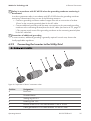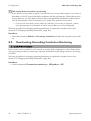
1
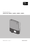
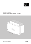
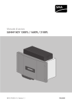
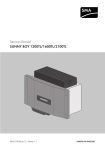
Operating Manual SUNNY BOY 1300TL / 1600TL / 2100TL SB13-21TL-BE-en-11 | 98-102300.01 | Version 1.1 AMERICAN ENGLISH Legal Provisions SMA Solar Technology AG Legal Provisions The information contained in these documents is property of SMA Solar Technology AG. Any publication, whether in whole or in part, requires prior written approval by SMA Solar Technology AG. Internal reproduction used solely for the purpose of product evaluation or other proper use is allowed and does not require prior approval. SMA Warranty You can download the current warranty conditions from the Internet at www.SMA-Solar.com. Trademarks All trademarks are recognized, even if not explicitly identified as such. A lack of identification does not mean that a product or symbol is not trademarked. The BLUETOOTH® word mark and logos are registered trademarks of Bluetooth SIG, Inc. and any use of these marks by SMA Solar Technology AG is under license. Modbus® is a registered trademark of Schneider Electric and is licensed by the Modbus Organization, Inc. QR Code is a registered trademark of DENSO WAVE INCORPORATED. Phillips® and Pozidriv® are registered trademarks of Phillips Screw Company. Torx® is a registered trademark of Acument Global Technologies, Inc. SMA Solar Technology AG Sonnenallee 1 34266 Niestetal Germany Tel. +49 561 9522-0 Fax +49 561 9522-100 www.SMA.de E-mail: [email protected] © 2004 to 2014 SMA Solar Technology AG. All rights reserved. 2 SB13-21TL-BE-en-11 Operating Manual SMA Solar Technology AG Table of Contents Table of Contents 1 2 Information on this Document ................................................. 5 1.1 1.2 1.3 1.4 1.5 Validity ................................................................................................ Target Group...................................................................................... Additional Information ....................................................................... Symbols .............................................................................................. Nomenclature..................................................................................... 5 5 5 6 6 Safety......................................................................................... 7 2.1 2.2 Intended Use ...................................................................................... 7 Safety Information.............................................................................. 7 3 Scope of Delivery...................................................................... 10 4 Product Description................................................................... 12 4.1 4.2 5 Mounting ................................................................................... 16 5.1 5.2 6 Sunny Boy........................................................................................... 12 Interfaces and Functions .................................................................... 14 Requirements for Mounting ............................................................... 16 Mounting the Inverter......................................................................... 19 Electrical Connection................................................................. 21 6.1 6.2 Safety during Electrical Connection.................................................. 21 Overview of the Connection Area .................................................... 22 6.2.1 6.2.2 6.3 AC Connection................................................................................... 23 6.3.1 6.3.2 6.3.3 6.4 6.5 Requirements for the AC Connection............................................ 23 Connecting the Inverter to the Utility Grid.................................... 25 Connecting Additional Grounding ............................................... 27 Connecting the Fault Indicator Relay................................................ 28 DC Connection................................................................................... 31 6.5.1 6.5.2 7 View from Below ............................................................................ 22 Interior View ................................................................................... 23 Requirements for the DC Connection............................................ 31 Connecting the PV Array ............................................................... 32 Commissioning.......................................................................... 35 Operating Manual SB13-21TL-BE-en-11 3 Table of Contents 7.1 7.2 7.3 7.4 Commissioning Procedure ................................................................. Changing the Display Language ...................................................... Commissioning the Inverter................................................................ Self-Test in Accordance with CEI 0-21 for PV Systems ≤6 kW ....... 7.4.1 7.4.2 8 35 35 36 37 Starting the Self-Test....................................................................... 37 Restarting the Self-Test ................................................................... 39 Configuration ............................................................................ 40 8.1 8.2 8.3 8.4 8.5 9 SMA Solar Technology AG Configuration Procedure.................................................................... Changing Operating Parameters...................................................... Integrating the Inverter into the Network.......................................... Configuring the Country Data Set..................................................... Deactivating Grounding Conductor Monitoring.............................. 40 40 41 41 42 Operation .................................................................................. 43 9.1 Display Messages.............................................................................. 43 9.1.1 9.1.2 9.2 9.3 9.4 Measuring Channels...................................................................... 43 Status Messages ............................................................................ 43 LED Signals ......................................................................................... 44 Activating and Operating the Display .............................................. 45 Calling Up Display Messages of the Start-Up Phase ...................... 45 10 Disconnecting the Inverter from Voltage Sources.................. 46 11 Technical Data........................................................................... 48 12 Accessories ................................................................................ 53 13 Contact....................................................................................... 54 14 EC Declaration of Conformity .................................................. 57 4 SB13-21TL-BE-en-11 Operating Manual 1 Information on this Document SMA Solar Technology AG 1 1.1 Information on this Document Validity This document is valid for the following device types from firmware version 4.50: • Sunny Boy 1300TL (SB 1300TL-10) • Sunny Boy 1600TL (SB 1600TL-10) • Sunny Boy 2100TL (SB 2100TL) 1.2 Target Group This document is intended for qualified persons and end users. Only qualified persons are allowed to perform the activities marked in this document with a warning symbol and the caption "Qualified person". Tasks that do not require any particular qualification are not marked and can also be performed by end users. Qualified persons must have the following skills: • Knowledge of how an inverter works and is operated • Training in how to deal with the dangers and risks associated with installing and using electrical devices and installations • Training in the installation and commissioning of electrical devices and installations • Knowledge of the applicable standards and directives • Knowledge of and compliance with this document and all safety information 1.3 Additional Information Links to additional information can be found at www.SMA-Solar.com: Document title and content Document type "Operating Parameters" Overview of All Inverter Operating Parameters and Their Configuration Options Technical Information "Order Form for the SMA Grid Guard Code" To apply for the SMA Grid Guard code to change grid-relevant operating parameters Certificate "Efficiency and Derating" Efficiency and Derating Behavior of the Sunny Boy, Sunny Tripower and Sunny Mini Central Inverters Technical Information "Circuit Breaker" Dimensioning and Selection of a Suitable AC Circuit Breaker for Inverters under PV-Specific Influences Technical Information "Module Technology" Use of Thin-Film and Back-Contact Modules Technical Information "Insulation Resistance (Riso) of Non-Galvanically Isolated PV Systems" Technical Information Operating Manual SB13-21TL-BE-en-11 5 1 Information on this Document SMA Solar Technology AG Document title and content Document type "Leading Leakage Currents" Information on the Design of Transformerless Inverters Technical Information "Temperature Derating" Technical Information "Criteria for Selecting a Residual-Current Device" Technical Information "Overvoltage protection" Technical Information 1.4 Symbols Symbol Explanation Indicates a hazardous situation which, if not avoided, will result in death or serious injury Indicates a hazardous situation which, if not avoided, can result in death or serious injury Indicates a hazardous situation which, if not avoided, can result in minor or moderate injury Indicates a situation which, if not avoided, can result in property damage Sections describing activities to be performed by qualified persons only Information that is important for a specific topic or goal, but is not safety-relevant Indicates a requirement for meeting a specific goal Desired result A problem that might occur 1.5 Nomenclature Complete designation Designation in this document Sunny Boy Inverter, product Electronic Solar Switch ESS SMA BLUETOOTH Wireless Technology BLUETOOTH 6 SB13-21TL-BE-en-11 Operating Manual 2 Safety SMA Solar Technology AG 2 2.1 Safety Intended Use The Sunny Boy is a transformerless PV inverter which converts the direct current of the PV array to grid-compliant alternating current and feeds it into the utility grid. The product is suitable for indoor and outdoor use. The product must only be operated with PV arrays of protection class II in accordance with IEC 61730, application class A. The PV modules must be compatible with this product. PV modules with a high capacity to ground must only be used if their coupling capacity does not exceed 1.4 μF (for information on how to calculate the coupling capacity, see the Technical Information "Leading Leakage Currents" at www.SMA-Solar.com). All components must remain within their permitted operating ranges at all times. The product must only be used in countries for which it is approved or released by SMA Solar Technology AG and the grid operator. Use this product only in accordance with the information provided in the enclosed documentation and with the locally applicable standards and directives. Any other application may cause personal injury or property damage. Alterations to the product, e.g. changes or modifications, are only permitted with the express written permission of SMA Solar Technology AG. Unauthorized alterations will void guarantee and warranty claims and usually void the operation permit. SMA Solar Technology AG shall not be held liable for any damage caused by such changes. Any use of the product other than that described in the Intended Use section does not qualify as appropriate. The enclosed documentation is an integral part of this product. Keep the documentation in a convenient place for future reference and observe all instructions contained therein. The type label must remain permanently attached to the product. 2.2 Safety Information This section contains safety information that must be observed at all times when working on or with the product. To prevent personal injury and property damage and to ensure long-term operation of the product, read this section carefully and observe all safety information at all times. Operating Manual SB13-21TL-BE-en-11 7 2 Safety SMA Solar Technology AG Danger to life due to high voltages of the PV array When exposed to sunlight, the PV array generates dangerous DC voltage which is present in the DC conductors and the live components of the inverter. Touching the DC conductors or the live components can lead to lethal electric shocks. If you disconnect the DC connectors from the inverter under load, an electric arc may occur leading to electric shock and burns. • Do not touch uninsulated cable ends. • Do not touch the DC conductors. • Do not touch any live components of the inverter. • Have the inverter mounted, installed and commissioned only by qualified persons with the appropriate skills. • If an error occurs, have it rectified by qualified persons only. • Prior to performing any work on the inverter, disconnect it from all voltage sources as described in this document (see Section 10 "Disconnecting the Inverter from Voltage Sources", page 46). Danger to life due to electric shock Touching an ungrounded PV module or array frame can cause a fatal electric shock. • Connect and ground the PV modules, array frame and electrically conductive surfaces so that there is continuous conduction. Observe the applicable local regulations. Risk of burns due to hot enclosure parts Some parts of the enclosure can get hot during operation. • During operation, do not touch any parts other than the enclosure lid of the inverter. Risk of burns from hot heat sink During operation, the heat sink at the top of the inverter can reach temperatures of over 70°C. • Do not touch the heat sink. • If the heat sink is soiled, clean it with a soft brush or a vacuum cleaner. 8 SB13-21TL-BE-en-11 Operating Manual 2 Safety SMA Solar Technology AG Dust and water intrusion can damage the inverter. If the inverter is equipped with an ESS, the inverter complies with degree of protection IP65 when the ESS is plugged in and the inverter is closed. If the ESS is not plugged in, moisture and dust can penetrate and damage the inverter. In order to sufficiently protect the inverter during decommissioning, the DC inputs must be closed. • Unlock and remove all DC connectors. • Open all DC connectors. • Close all DC inputs with the corresponding DC connectors and the supplied sealing plugs. • Securely plug the ESS back in. Damage to the display or the type label due to the use of cleaning agents • If the inverter is dirty, clean the enclosure, the enclosure lid, the type label, the display and the LEDs with a damp cloth only. Operating Manual SB13-21TL-BE-en-11 9 3 Scope of Delivery 3 SMA Solar Technology AG Scope of Delivery Check the scope of delivery for completeness and any externally visible damage. Contact your distributor if the scope of delivery is incomplete or damaged. Figure 1: Components included in the scope of delivery Position Quantity Designation A 1 Sunny Boy B 1 Wall mounting bracket C 1 Electronic Solar Switch (ESS)* D 1/2 Positive DC connector SB 1300TL-10 / 1600TL-10: 1 pc. SB 2100TL: 2 pcs. E 1/2 Negative DC connector SB 1300TL-10 / 1600TL-10: 1 pc. SB 2100TL: 2 pcs. F 2/4 Sealing plug SB 1300TL-10 / 1600TL-10: 2 pcs. SB 2100TL: 4 pcs. G 1 Protective cap for AC pin connector on inverter H 1 AC connection socket: bush insert, threaded sleeve, pressure screw PG13.5, sealing ring PG13.5, fastening case PG13.5, cable gland M20x1.5 I 1 M6x12 cylindrical screw K 1 Conical spring washer L 1 Jumper M 1 Cable gland PG16 with single-hole cable support sleeve 10 SB13-21TL-BE-en-11 Operating Manual 3 Scope of Delivery SMA Solar Technology AG Position Quantity Designation N 1 Operating manual, supplementary sheet with inverter default settings O 1 Speedwire/Webconnect interface * Optional Operating Manual SB13-21TL-BE-en-11 11 4 Product Description 4 SMA Solar Technology AG Product Description 4.1 Sunny Boy The Sunny Boy is a transformerless PV inverter which converts the direct current of the PV array to grid-compliant alternating current and feeds it into the utility grid. Figure 2: Design of the Sunny Boy Position Designation A Type label The type label uniquely identifies the inverter. You will require the information on the type label to use the product safely and when seeking customer support from the SMA Service Line. You will find the following information on the type label: • Device type (Model) • Serial number (Serial No.) • Date of manufacture • Device-specific characteristics B LEDs The LEDs indicate the operating state of the inverter (see Section 9.2 "LED Signals", page 44). C Electronic Solar Switch (ESS)* The ESS and the DC connectors together form a DC load-break switch. When plugged in, the ESS forms a conductive path between the PV array and the inverter. Removing the ESS interrupts the DC electric circuit and removing all DC connectors disconnects the PV array completely from the inverter. D Display The display shows the current operating data and errors. E Enclosure lid * Optional 12 SB13-21TL-BE-en-11 Operating Manual 4 Product Description SMA Solar Technology AG Symbols on the Inverter and on the Type Label Symbol Explanation By tapping on the enclosure lid, you can activate and operate the display (see Section 9.3, page 45). Inverter Together with the green LED, this symbol indicates the operating state of the inverter. Ground fault Together with the red LED, this symbol indicates the presence of a ground fault in the PV array or that at least one of the varistors in the inverter is defective (for troubleshooting, see service manual at www.SMA-Solar.com). Observe the documentation. Together with the yellow LED, this symbol indicates an error or a disturbance (for troubleshooting, see the service manual at www.SMA-Solar.com). Operating principle of the ESS*: • If the ESS is plugged in, the DC electric circuit is closed. • To interrupt the DC electric circuit, you must perform the following steps in the given order: – Remove the ESS. – Unlock and remove all DC connectors. Grounding conductor This symbol indicates the position for the grounding conductor terminal. Danger to life due to high voltages in the inverter; observe the waiting time of ten minutes. High voltages that can cause lethal electric shocks are present in the live components of the inverter. Prior to performing any work on the inverter always disconnect it from all voltage sources as described in this document (see Section 10 "Disconnecting the Inverter from Voltage Sources", page 46). Danger to life due to electric shock The product operates at high voltages. All work on the product must be carried out by qualified persons only. Operating Manual SB13-21TL-BE-en-11 13 4 Product Description Symbol SMA Solar Technology AG Explanation Risk of burns due to hot surfaces The product can get hot during operation. Avoid contact during operation. Allow the product to cool down sufficiently before carrying out any work. Observe the documentation. Observe all documentation supplied with the product. Direct current The product does not have a transformer. Alternating current WEEE designation Do not dispose of the product together with the household waste but in accordance with the locally applicable disposal regulations for electronic waste. CE marking The product complies with the requirements of the applicable EU directives. Degree of protection IP65 The product is protected against dust intrusion and water jets from any angle. The product is suitable for outdoor installation. RCM (Regulatory Compliance Mark) The product complies with the requirements of the applicable Australian standards. * Optional 4.2 Interfaces and Functions The inverter can be equipped or retrofitted with the following interfaces and functions: 14 SB13-21TL-BE-en-11 Operating Manual SMA Solar Technology AG 4 Product Description BLUETOOTH Via BLUETOOTH, the inverter can communicate with various BLUETOOTH devices (for information on supported SMA products, see www.SMA-Solar.com). The BLUETOOTH interface can be retrofitted. SMA Speedwire/Webconnect The inverter is equipped with SMA Speedwire/Webconnect as standard. SMA Speedwire/ Webconnect is a type of communication based on the Ethernet standard. This enables inverteroptimized 10/100 Mbit data transmission between Speedwire devices in PV systems and the software Sunny Explorer. The Webconnect function enables direct data transmission between the inverters of a small-scale system and the Internet portal Sunny Portal without any additional communication device and for a maximum of four inverters per Sunny Portal system. In large-scale PV power plants, data transmission to the Internet portal Sunny Portal is carried out via the SMA Cluster Controller. You can access your Sunny Portal system from any computer with an Internet connection. SMA Speedwire/Webconnect enables, for PV systems operated in Italy, the connection to or disconnection of the inverter from the utility grid and definition of the frequency limits to be used with IEC61850-GOOSE messages. RS485 interface The inverter can communicate via cables with special SMA communication products via the RS485 interface (information on supported SMA products at www.SMA-Solar.com). The RS485 interface can be retrofitted. Grid Management Services The inverter is equipped with service functions for grid management. Depending on the requirements of the grid operator, you can activate and configure the functions (e.g. active power limitation) via operating parameters. Fault indicator relay The inverter is equipped with a fault indicator relay which will signal faults depending on the type of output device connected. You can connect your own load to this relay (e.g. warning light, acoustic signal) (see Section 6.4 "Connecting the Fault Indicator Relay", page 28). All-pole sensitive residual-current monitoring unit The all-pole sensitive residual-current monitoring unit detects alternating and direct differential currents. In single-phase and three-phase inverters, the integrated differential current sensor detects the current difference between the neutral conductor and the line conductor(s). If the current difference increases suddenly, the inverter disconnects from the utility grid. Operating Manual SB13-21TL-BE-en-11 15 5 Mounting 5 5.1 SMA Solar Technology AG Mounting Requirements for Mounting Requirements for the mounting location: Danger to life due to fire or explosion Despite careful construction, electrical devices can cause fires. • Do not mount the inverter in areas containing highly flammable materials or gases. • Do not mount the inverter in a potentially explosive atmosphere. ☐ The mounting location must be inaccessible to children. ☐ A solid support surface must be available for mounting, e.g. concrete or masonry. When mounted on drywall or similar materials in the living area, the inverter emits audible vibrations during operation which could be perceived as annoying. ☐ The mounting location must be suitable for the weight and dimensions of the inverter (see Section 11 "Technical Data", page 48). ☐ To ensure optimum operation, the ambient temperature should be between -25°C and 40°C. ☐ The mounting location should not be exposed to direct solar irradiation. Direct solar irradiation can cause the inverter to overheat. As a result, the inverter reduces its power output. ☐ Climatic conditions must be met (see Section 11 "Technical Data", page 48). ☐ The mounting location should be freely and safely accessible at all times without the need for any auxiliary equipment (such as scaffolding or lifting platforms). Non-fulfillment of these criteria may restrict servicing. 16 SB13-21TL-BE-en-11 Operating Manual 5 Mounting SMA Solar Technology AG Dimensions for mounting: Figure 3: Position of the anchoring points Recommended clearances: If you maintain the recommended clearances, adequate heat dissipation will be ensured. Thus, you will prevent power reduction due to excessive temperature. ☐ Maintain the recommended clearances to walls as well as to other inverters or objects. ☐ If multiple inverters are mounted in areas with high ambient temperatures, increase the clearances between the inverters and ensure sufficient fresh-air supply. Operating Manual SB13-21TL-BE-en-11 17 5 Mounting SMA Solar Technology AG Figure 4: Recommended clearances Permitted and prohibited mounting positions: ☐ The inverter must be mounted in one of the permitted positions. This will ensure that no moisture can penetrate the inverter. ☐ The inverter should be mounted in such way that display messages and LED signals can be read without difficulty. Figure 5: Permitted and prohibited mounting positions 18 SB13-21TL-BE-en-11 Operating Manual 5 Mounting SMA Solar Technology AG 5.2 Mounting the Inverter Additionally required mounting material (not included in the scope of delivery): ☐ Two screws that are suitable for the support surface and the weight of the inverter ☐ Two washers suitable for the screws ☐ If necessary, two screw anchors suitable for the support surface and the screws Risk of injury when lifting the inverter, or if it is dropped The inverter weighs 16 kg. There is risk of injury if the inverter is lifted incorrectly or dropped while being transported or when attaching it to or removing it from the wall mounting bracket. • Transport and lift the inverter carefully. Procedure: 1. Risk of injury due to damaged cables There may be power lines or other supply lines (e.g. gas or water) routed in the wall. • Ensure that no lines are laid in the wall which could be damaged when drilling holes. 2. Align the wall mounting bracket horizontally on the wall and use it to mark the position of the drill holes. 3. Set the wall mounting bracket aside and drill the marked holes. 4. Insert screw anchors into the drill holes if the support surface requires them. 5. Secure the wall mounting bracket horizontally using screws and washers. 6. Hook the inverter into the wall mounting bracket, ensuring that it cannot slide sideways out of the bracket. 7. If local requirements stipulate the connection of additional grounding or equipotential bonding, you must connect additional grounding to the inverter (see Section 6.3.3, page 27). Operating Manual SB13-21TL-BE-en-11 19 5 Mounting SMA Solar Technology AG 8. If no additional grounding or equipotential bonding is required, secure the inverter to the wall mounting bracket with the M6x12 screw to prevent it from being lifted off. 9. Ensure that the inverter is securely in place. 20 SB13-21TL-BE-en-11 Operating Manual SMA Solar Technology AG 6 6.1 6 Electrical Connection Electrical Connection Safety during Electrical Connection Danger to life due to high voltages of the PV array When exposed to sunlight, the PV array generates dangerous DC voltage which is present in the DC conductors and the live components of the inverter. Touching the DC conductors or the live components can lead to lethal electric shocks. If you disconnect the DC connectors from the inverter under load, an electric arc may occur leading to electric shock and burns. • Do not touch uninsulated cable ends. • Do not touch the DC conductors. • Do not touch any live components of the inverter. • Have the inverter mounted, installed and commissioned only by qualified persons with the appropriate skills. • If an error occurs, have it rectified by qualified persons only. • Prior to performing any work on the inverter, disconnect it from all voltage sources as described in this document (see Section 10 "Disconnecting the Inverter from Voltage Sources", page 46). Damage to the inverter due to electrostatic discharge Touching electronic components can cause damage to or destroy the inverter through electrostatic discharge. • Ground yourself before touching any component. Operating Manual SB13-21TL-BE-en-11 21 6 Electrical Connection 6.2 6.2.1 SMA Solar Technology AG Overview of the Connection Area View from Below Figure 6: Connection areas and enclosure openings at the bottom of the inverter Position Designation A Positive DC connector* B Pin connector for the ESS** C Negative DC connector* D Enclosure opening with filler plug for the connection cable of the multifunction relay E Enclosure opening with filler plug for the data cables or network cables E Pin connector for the AC connection socket * As standard, SB 1300TL and SB 1600TL-10 are equipped with a positive and a negative DC connector ** Optional 22 SB13-21TL-BE-en-11 Operating Manual SMA Solar Technology AG 6.2.2 6 Electrical Connection Interior View Figure 7: Connection areas in the interior of the inverter Position Designation A Slot and connection area for an SMA communication interface B Flat male tab for grounding the cable shield when communication takes place via RS485 C Fuse for the ESS* * Optional 6.3 6.3.1 AC Connection Requirements for the AC Connection Cable requirements: ☐ External diameter: 5 mm to 13 mm ☐ Conductor cross-section: 1.5 mm² to 2.5 mm² Operating Manual SB13-21TL-BE-en-11 23 6 Electrical Connection SMA Solar Technology AG ☐ Insulation stripping length: 4 mm ☐ The cable must be dimensioned in accordance with the local and national directives for the dimensioning of cables. The requirements for the minimum wire size derive from these directives. Examples of factors influencing cable dimensioning are: nominal AC current, type of cable, routing method, cable bundling, ambient temperature and maximum desired line losses (for calculation of line losses, see the design software "Sunny Design" from software version 2.0 at www.SMA-Solar.com). Load-break switch and cable protection: Damage to the inverter due to the use of screw-type fuses as load-break switches Screw-type fuses (e.g. DIAZED fuse or NEOZED fuse) are not load-break switches. • Do not use screw-type fuses as load-break switches. • Use a load-break switch or circuit breaker as a load disconnection unit (for information and design examples, see the Technical Information "Circuit Breaker" at www.SMA-Solar.com). ☐ In PV systems with multiple inverters, protect each inverter with a separate circuit breaker. Make sure to observe the maximum permissible fuse protection (see Section 11 "Technical Data", page 48). This will prevent residual voltage being present at the corresponding cable after disconnection. ☐ Loads installed between the inverter and the circuit breaker must be fused separately. Residual-current monitoring unit: ☐ If an external residual-current device is required, install a residual-current device which trips at a residual current of 100 mA or higher (for details on selecting a residual-current device, see the Technical Information "Criteria for Selecting a Residual-Current Device" at www.SMASolar.com). Overvoltage category: The inverter can be used in grids of installation category III or lower in accordance with IEC 60664-1. That means that the inverter can be permanently connected to the grid-connection point of a building. In case of installations with long outdoor cabling routes, additional measures to reduce overvoltage category IV to overvoltage category III are required (see the Technical Information "Overvoltage protection" at www.SMA-Solar.com). Grounding conductor monitoring: The inverter is equipped with a grounding conductor monitoring device. This grounding conductor monitoring device detects when there is no grounding conductor connected and disconnects the inverter from the utility grid if this is the case. Depending on the installation site and grid configuration, it may be advisable to deactivate the grounding conductor monitoring. This is necessary, for example, in an IT system if there is no neutral conductor present and you intend to install the inverter between two line conductors. If you are uncertain about this, contact your grid operator or SMA Solar Technology AG. ☐ Grounding conductor monitoring must be deactivated after initial start-up depending on the grid configuration (see Section 8.5, page 42). 24 SB13-21TL-BE-en-11 Operating Manual 6 Electrical Connection SMA Solar Technology AG Safety in accordance with IEC 62109 when the grounding conductor monitoring is deactivated In order to guarantee safety in accordance with IEC 62109 when the grounding conductor monitoring is deactivated, carry out one of the following measures: • Connect a grounding conductor made of copper wire with a cross-section of at least 10 mm² to the connecting terminal plate for the AC cable. • Connect additional grounding with the same cross-section as the connected grounding conductor to the connecting terminal plate for the AC cable (see Section 6.3.3, page 27 ). This prevents touch current if the grounding conductor at the connecting terminal plate for the AC cable fails. Connection of additional grounding In some countries, additional grounding is generally required. In each case, observe the locally applicable regulations. 6.3.2 Connecting the Inverter to the Utility Grid Figure 8: Components of the AC connection socket Position Designation A Bush insert B Threaded sleeve C Sealing ring PG13.5 D Fastening case 13.5 E Pressure screw PG13.5 for cable diameter 7 mm to 10 mm F Cable gland M20x1.5 for cable diameter 10 mm to 14 mm Operating Manual SB13-21TL-BE-en-11 25 6 Electrical Connection SMA Solar Technology AG Requirements: ☐ The connection requirements of the grid operator must be met. ☐ The grid voltage must be in the permissible range. The exact operating range of the inverter is specified in the operating parameters (see the Technical Description "Operating Parameters" at www.SMA-Solar.com). Procedure: 1. Select a suitable cable gland for the AC cable. 2. Disconnect the circuit breaker and secure it against reconnection. 3. Dismantle the AC cable by 30 mm. 4. Shorten L and N by 5 mm each. 5. Strip the insulation of L, N and the grounding conductor by 4 mm. 6. If the cable diameter is between 7 mm and 10 mm, use sealing ring, fastening case and pressure screw as follows: • Push the sealing ring into the fastening case. • Thread the PG13.5 pressure screw and the fastening case with sealing ring onto the AC cable. 7. If the external cable diameter is between 10 mm and 14 mm, thread cable gland M20x1.5 onto the AC cable. 8. Slide the threaded sleeve over the AC cable. 9. Connect the grounding conductor, N and L to the bush insert as follows: • Insert the grounding conductor into the screw terminal with the ground symbol on the bush insert and tighten the screw. 26 SB13-21TL-BE-en-11 Operating Manual SMA Solar Technology AG 6 Electrical Connection • Insert N (or respectively L2 in case of split phase) into screw terminal 1 on the bush insert and tighten the screw. • Insert L (or respectively L1 in case of split phase) into screw terminal 2 on the bush insert and tighten the screw. 10. Ensure that all conductors are securely in place in the bush insert. 11. Screw the threaded sleeve tightly onto the bush insert. 12. When using pressure screw, fastening case and sealing ring, screw the pressure screw firmly onto the threaded sleeve. The fastening case will be pressed into the threaded sleeve and no longer be visible. 13. When using the cable gland, screw the cable gland firmly onto the threaded sleeve. ☑ The AC connection socket is mounted. 14. Insert the AC connection socket into the AC pin connector on the inverter. Remove the protective cap from the AC pin connector beforehand, if required. 15. If the AC connection socket is not to be connected to the inverter immediately, close the AC pin connector on the inverter with the protective cap provided. 6.3.3 Connecting Additional Grounding If additional grounding or equipotential bonding is required locally, you can connect additional grounding to the inverter. This prevents touch current if the grounding conductor at the connecting terminal plate for the AC cable fails. The required clamping bracket, the screw and the conical spring washer are part of the scope of delivery of the inverter. Operating Manual SB13-21TL-BE-en-11 27 6 Electrical Connection SMA Solar Technology AG Additionally required material (not included in the scope of delivery): ☐ Ring terminal lug M6 ☐ 1 grounding cable Cable requirement: ☐ Grounding cable cross-section: max. 16 mm² Procedure: 1. Strip the grounding cable insulation. 2. Thread the ring terminal lug onto the grounding cable. 3. Align washer, grounding cable with ring terminal lug and conical spring washer on the cylindrical screw M6x12. The teeth of the conical spring washer must be facing the metal shackle on the inverter. 4. Insert the cylindrical screw through the metal shackle on the inverter and screw it onto the wall mounting bracket (torque: 6 Nm). 6.4 Connecting the Fault Indicator Relay You can use the fault indicator relay to have inverter errors displayed or reported. This requires a parallel connection. Alternatively, you can choose to have fault-free operation displayed or reported. This requires a series connection. You can connect several inverters to one fault indicator or operation indicator. You must connect the fault indicator relay of several inverters in parallel. In case of critical disturbances, the fault indicator relay will close immediately and trip the warning signal through the connected load. In case of non-critical disturbances, the fault indicator relay will only close after several flashing cycles of the yellow LED. When the inverter reconnects to the utility grid, the fault indicator relay opens again. Error message required by standard In some countries, signaling of errors is required by standards, e.g. IEC 62109-2. In order to meet the standard requirement, take one of the following measures: • Connect a display device to the fault indicator relay which signals either an error or the undisturbed operation of the inverter. • Activate the error alarm in Sunny Portal (for information on receiving error alarms via Sunny Portal, see the Sunny Portal user manual at www.SunnyPortal.com). This requires the inverter to be registered in Sunny Portal. 28 SB13-21TL-BE-en-11 Operating Manual SMA Solar Technology AG 6 Electrical Connection Connection plan: Figure 9: Circuit diagram with multiple inverters for connection to an operation indicator and circuit diagram for connection to a fault indicator (example) Operating Manual SB13-21TL-BE-en-11 29 6 Electrical Connection SMA Solar Technology AG Overview of the connection area: Figure 10: Fault indicator relay inside the inverter Position Designation A Terminals of the fault indicator relay B Cable route C Enclosure opening with filler plug Requirement: ☐ The technical requirements of the fault indicator relay must be complied with (see Section 11 "Technical Data", page 48). Cable requirements: ☐ The cable must be double-insulated. ☐ External diameter: 5 mm to 12 mm ☐ Conductor cross-section: 0.08 mm² to 2.5 mm² ☐ The cable type and cable-laying method must be appropriate for the application and location. Destruction of the fault indicator relay as a result of contact overload • Observe the maximum switching voltage and maximum switching current (see Section 11 "Technical Data", page 48). • When connecting the fault indicator relay to the utility grid, protect it with an individual circuit breaker. 30 SB13-21TL-BE-en-11 Operating Manual SMA Solar Technology AG 6 Electrical Connection Procedure: 1. Danger to life due to electric shock • Ensure that the inverter is disconnected from all voltage sources (see Section 10 "Disconnecting the Inverter from Voltage Sources", page 46). 2. Remove all screws from the enclosure lid and pull the enclosure lid forward smoothly. 3. Remove the grounding conductor from the bottom of the enclosure lid. 4. Prepare the cable: • Dismantle the cable by no more than 15 mm. • Strip off the conductor insulation by max. 8 mm. 5. Prepare the cable gland PG16 for connection to the fault indicator relay as follows: • Remove the swivel nut from the cable gland and remove the filler plug. • Remove the one-hole cable support sleeve from the cable gland and insert the cable into the one-hole cable support sleeve. • Press the one-hole cable support sleeve with the cable into the cable gland and lead the cable into the inverter. • Slide the swivel nut over the cable. 6. Connect the cable to the fault indicator relay in accordance with the circuit diagram. 7. Tighten the swivel nut of the cable gland. 8. Establish the grounding conductor connection between the inverter and enclosure lid. 9. Position the enclosure lid on the enclosure and tighten it using the four screws (torque: 2 Nm). 6.5 6.5.1 DC Connection Requirements for the DC Connection Requirements for the PV modules: ☐ All PV modules must be of the same type. ☐ All PV modules must be aligned and tilted identically. ☐ On the coldest day based on statistical records, the open-circuit voltage of the PV array must never exceed the maximum input voltage of the inverter. ☐ The same number of series-connected PV modules must be connected to each string. ☐ The maximum input current per string must be maintained and must not exceed the throughfault current of the DC connectors (see Section 11 "Technical Data", page 48). Operating Manual SB13-21TL-BE-en-11 31 6 Electrical Connection SMA Solar Technology AG ☐ The thresholds for the input voltage and the input current of the inverter must be adhered to (see Section 11 "Technical Data", page 48). ☐ The positive connection cables of the PV modules must be fitted with the positive DC connectors (for information on assembling DC connectors, see the DC connector installation manual). ☐ The negative connection cables of the PV modules must be fitted with the negative DC connectors (for information on assembling DC connectors, see the DC connector installation manual). ☐ If the inverter is not equipped with an ESS and the regulations in the country of installation require an external DC load-break switch, you must install an external DC load-break switch. Use of Y adapters for parallel connection of strings The Y adapters must not be used to interrupt the DC circuit. • Do not use the Y adapters in the immediate vicinity of the inverter. The adapters must not be visible or freely accessible. • In order to interrupt the DC circuit, always disconnect the inverter as described in this document (see Section 10, page 46). 6.5.2 Connecting the PV Array Destruction of the inverter due to overvoltage If the open-circuit voltage of the PV modules exceeds the maximum input voltage of the inverter, the inverter can be destroyed due to overvoltage. • If the open-circuit voltage of the PV modules exceeds the maximum input voltage of the inverter, do not connect any strings to the inverter and check the design of the PV system. Damage to the DC connectors due the use of contact cleaner of other cleaning agents Some contact cleaners or other cleaning agents may contain substances that decompose the plastic of the DC connectors. • Do not use contact cleaners or other cleaning agents for cleaning the DC connectors. Procedure: 1. Ensure that the circuit breaker is switched off and that it cannot be reconnected. 2. If an external DC load-break switch is installed, disconnect it from all voltage sources. 3. If the ESS is installed and plugged in, carefully remove the ESS. 4. Ensure that there is no ground fault in the PV array (see service manual at www.SMASolar.com). 32 SB13-21TL-BE-en-11 Operating Manual SMA Solar Technology AG 6 Electrical Connection 5. Check whether the DC connectors have the correct polarity. If the DC connector is equipped with a DC cable of the wrong polarity, the DC connector must be assembled again. The DC cable must always have the same polarity as the DC connector. 6. Ensure that the open-circuit voltage of the PV array does not exceed the maximum input voltage. 7. Connect the assembled DC connectors to the inverter. ☑ The DC connectors snap into place. Operating Manual SB13-21TL-BE-en-11 33 6 Electrical Connection SMA Solar Technology AG 8. Damage to the inverter due to moisture ingress The inverter is only properly sealed when all unused DC inputs are closed with DC connectors and sealing plugs. • Do not insert the sealing plugs directly into the DC inputs on the inverter. • For unused DC connectors, push down the clamping bracket and push the swivel nut up to the thread. • Insert the sealing plug into the DC connector. • Tighten the DC connector (torque: 2 Nm). • Insert the DC connectors with sealing plugs into the corresponding DC inputs on the inverter. ☑ The DC connectors snap into place. 9. Ensure that all DC connectors are securely in place. 34 SB13-21TL-BE-en-11 Operating Manual 7 Commissioning SMA Solar Technology AG 7 Commissioning 7.1 Commissioning Procedure Procedure See 1. Connect to the communication interface. Installation manual of the communication interface 2. If the display language is not set correctly, adjust the settings. Section 7.2, page 35 3. Commission the inverter and start a self-test, if required. Section 7.3, page 36 and Section 7.4, page 37 7.2 Changing the Display Language Use the following figure to check whether the display language of the inverter is set correctly. If the display language is not correct, you can change the display language of the inverter as described in the following. Various languages are available depending on the country data set selected. Figure 11: Switch for setting the display language Language Switch S2 Switch S1 B B English / Italian* B A French A B Spanish / English** A A German * When country data set CEI 0-21 is selected, the language is Italian. ** When country data set CEI 0-21 is selected, the language is English. Procedure: 1. Danger to life due to electric shock • Ensure that the inverter is disconnected from all voltage sources (see Section 10 "Disconnecting the Inverter from Voltage Sources", page 46). Operating Manual SB13-21TL-BE-en-11 35 7 Commissioning 2. 3. 4. 5. 6. 7. SMA Solar Technology AG Remove all screws from the enclosure lid and pull the enclosure lid forward smoothly. Remove the grounding conductor from the bottom of the enclosure lid. Set the switches A and B in accordance with the desired language. Connect the grounding conductor of the inverter to the bottom side of the enclosure lid. Position the enclosure lid on the enclosure and tighten it using the four screws (torque: 2 Nm). Commission the inverter (see Section 7.3, page 36). 7.3 Commissioning the Inverter Requirements: ☐ The inverter must be correctly mounted. ☐ The circuit breaker must be correctly rated and mounted. ☐ All cables must be correctly connected. ☐ Unused DC inputs must be sealed using the corresponding DC connectors and sealing plugs. ☐ The country data set must be set correctly for the country or the purpose. ☐ If the inverter is equipped with a BLUETOOTH interface, the NetID must be set (see installation manual of the BLUETOOTH interface). ☐ The grounding conductor of the inverter must be connected to the bottom of the enclosure lid. ☐ The enclosure lid of the inverter must be firmly tightened. Procedure: 1. If the ESS is available, plug it in. 2. Risk of fire due to tightening the screw within the ESS A perfect contact between the ESS and the inverter is only guaranteed if the ESS plug remains flexible. • Do not tighten the screw in the plug of the ESS. 3. Damage to the inverter due to moisture and dust intrusion If the ESS is not plugged in or incorrectly plugged in during operation, moisture and dust can penetrate the inverter. If the ESS is not correctly plugged in, this can cause contacts in the ESS to wear or the ESS might fall out. This can result in yield loss and damage to the ESS. Always plug in the ESS as follows: • Firmly plug the ESS in until it is flush with the enclosure. • Ensure that the gap between the ESS and the enclosure is no more than 1 mm. 4. If an external DC load-break switch is installed, switch it on. 5. Switch on the circuit breaker. ☑ The start-up phase begins. 36 SB13-21TL-BE-en-11 Operating Manual SMA Solar Technology AG 7 Commissioning Self-test in accordance with CEI 0-21 during commissioning (applies to Italy only) The Italian standard prescribes that an inverter can only operate on the utility grid after the disconnection times for overvoltage, undervoltage, minimum frequency and maximum frequency have been checked. • If the country data set CEI 0-21 Int / CEI 0-21 internal is set, start the self-test as soon as the display shows the country data set (see Section 7.4.1, page 37). ☑ The green LED is glowing and the display alternates automatically between the device type or designation of the inverter, the firmware version and the configured country data set. ✖ The green LED is flashing? The DC input voltage is still too low or the inverter is checking the utility grid. • Once the DC input voltage is sufficiently high and the grid connection conditions are met, the inverter will start operation. ✖ The red LED is glowing? The inverter has detected a ground fault or one of the varistors is defective. • Rectify the error (see the service manual at www.SMA-Solar.com). ✖ The yellow LED is glowing or flashing? An error or disturbance has occurred. • Rectify the error or disturbance (see service manual at www.SMA-Solar.com). ✖ All LEDs are flashing? The DC voltage is still too low and the start-up phase begins again. No error has occurred. • Waiting for sufficient irradiation ✖ All LEDs have gone out? The inverter is switched off because the ESS is not plugged in, the external DC load-break switch is not switched on or irradiation is not sufficient. • Ensure that the ESS is plugged in correctly or that the external DC load-break switch is switched on. 7.4 7.4.1 Self-Test in Accordance with CEI 0-21 for PV Systems ≤6 kW Starting the Self-Test The self-test only applies to inverters that are configured with the country data set CEI 0-21 Int or CEI 0-21 internal. The self-test is only valid for inverters licensed for Italy and configured with the country data set CEI0-21 Int or CEI 0-21 internal. The self-test is only required for inverters to be commissioned in Italy. The Italian standard requires that all inverters feeding into the utility grid are equipped with a self-test function in accordance with CEI 0-21. During the self-test, the inverter will consecutively check the reaction times for overvoltage, undervoltage, maximum frequency and minimum frequency. Operating Manual SB13-21TL-BE-en-11 37 7 Commissioning SMA Solar Technology AG The self-test changes the upper and lower disconnection values for each protective function on a linear basis for frequency monitoring and voltage monitoring. As soon as the measured value exceeds the permitted disconnection threshold, the inverter disconnects from the utility grid. In this way, the inverter determines the reaction time and checks itself. After the self-test has been completed, the inverter automatically switches back to feed-in operation, resets the original disconnection conditions and connects to the utility grid. The test takes approximately three minutes. Requirements: ☐ Configured country data set: CEI 0-21 Int or CEI 0-21 internal or amended country data set trimmed or Special setting based on one of the country data sets mentioned above. ☐ A report for entering the test results according to CEI 0-21 must be available. ☐ The inverter must be in operation and in the start-up phase. Procedure: 1. As soon as the configured country data set appears in the display, tap once on the display within ten seconds. ☑ A message informing you that the self-test has started is shown in the display: Avvio Autotest. ✖ The message Avvio Autotest is not shown in the display? The ten seconds have elapsed so the self-test cannot start. • Restart the self-test (see Section 7.4.2, page 39). 2. Tap on the display within 20 seconds and enter the subsequent test results into the test report. ☑ The self-test starts. ☑ The inverter displays the results of the individual tests for overvoltage, undervoltage, maximum frequency and minimum frequency. The results are displayed three times in succession for ten seconds each. Useful hint: If you want to have the next result displayed without waiting ten seconds, tap twice on the enclosure lid. ✖ The information Autotest interroto is shown in the display? The self-test was cancelled due to an unexpected disconnection condition or the DC voltage is too low to continue grid feed-in. • Restart the self-test (see Section 7.4.2, page 39). Example: Display messages for overvoltage test - Name of the test: Autotest (59.S1) 240.00V - Disconnection value: Valore di soglia con 230.00V - Normative value: Va. taratura 253.00V - Disconnection time: Tempo die intervento 0.02 s - Current grid voltage: Tensione di rete Val.eff.: 229.80V 38 SB13-21TL-BE-en-11 Operating Manual SMA Solar Technology AG 7.4.2 7 Commissioning Restarting the Self-Test 1. Disconnect the circuit breaker and secure it against reconnection. 2. If the fault indicator relay is used, switch off the load supply voltage, if necessary. 3. If an external DC load-break switch is in use, switch it off for five minutes and then switch it on again. 4. If an ESS is in use, pull it out of the inverter for five minutes and then plug it in again firmly. 5. Recommission the inverter (see Section 7.3, page 36). ☑ The inverter is back in the start-up phase and you can start the self-test once again (see Section 7.4.1, page 37). Operating Manual SB13-21TL-BE-en-11 39 8 Configuration 8 SMA Solar Technology AG Configuration 8.1 Configuration Procedure Once you have commissioned the inverter, you may have to adjust various settings via a communication product. This section describes the procedure for configuration and gives an overview of the steps you must perform in the prescribed order. Procedure See 1. If the inverter is equipped with a communication inter- Manual of the communication face, detect the inverter by means of a communication product at www.SMA-Solar.com product. This way, you can manage the data of the system or set inverter parameters. 2. If the inverter is equipped with a Speedwire/Webconnect interface, and the Webconnect function is to be used, integrate the inverter in the network. Section 8.3, page 41 3. Check which country data set the inverter is set to. Supplementary sheet with the default settings, type label or display 4. If the country data set is not set correctly for your coun- Section 8.4, page 41 try or your purpose, adjust to the required country data set. 5. Change the system time and system password. 6. If the inverter is installed in an IT network or another Section 8.5, page 42 grid configuration where deactivation of the grounding conductor monitoring is required, deactivate the grounding conductor monitoring. 8.2 Manual of the communication product at www.SMA-Solar.com Changing Operating Parameters This section describes the basic procedure for changing operating parameters. Always change operating parameters as described in this section. Some parameters that have sensitive functions can only be viewed and changed by qualified persons (for further information on changing parameters, refer to the manual of the communication product). The operating parameters of the inverter are set to certain values by default. To optimize inverter operation, you can change the operating parameters using a communication product. Requirements: ☐ Depending on the type of communication, a computer with a BLUETOOTH or Ethernet interface must be available. 40 SB13-21TL-BE-en-11 Operating Manual 8 Configuration SMA Solar Technology AG ☐ A communication product corresponding to the type of communication used must be available. ☐ The inverter must be registered in the communication product. ☐ The changes to the grid-relevant parameters must be approved by the responsible grid operator. ☐ When changing grid-relevant parameters, the SMA Grid Guard code must be available (see the Certificate "Order Form for the SMA Grid Guard Code" at www.SMA-Solar.com). Procedure: 1. Call up the user interface of the communication product or software and log in as Installer or User. 2. If required, enter the SMA Grid Guard code. 3. Select and set the required parameter. 4. Save settings. 8.3 Integrating the Inverter into the Network If the router supports DHCP and DHCP is enabled, the inverter will automatically be integrated into the network. You will not need to carry out network configuration. If the router does not support DHCP, automatic network configuration will not be possible and you will need to use SMA Connection Assist to integrate the inverter into the network. Requirements: ☐ The inverter must be in operation. ☐ There must be a router with Internet connection in the local network of the system. ☐ The inverter must be connected to the router. Procedure: • Integrate the inverter into the network by means of the SMA Connection Assist. Download the SMA Connection Assist and install it on the computer (see www.SMA-Solar.com). 8.4 Configuring the Country Data Set By default, the inverter is set to a specific country data set. You can find the country data set to which the inverter has been set on the enclosed supplementary sheet with the default settings or on the type label. Each country data set contains various operating parameters which can be individually set according to the respective country. You can change the parameters by means of a communication product. Operating Manual SB13-21TL-BE-en-11 41 8 Configuration SMA Solar Technology AG The country data set must be set correctly. If you select a country data set which is not valid for your country and purpose, it can cause a disturbance in the PV system and lead to problems with the grid operator. When selecting the country data set, you must always observe the locally applicable standards and directives as well as the properties of the PV system (e.g. PV system size, grid-connection point). • If you are not sure which country data set is valid for your country or purpose, contact your grid operator for information on which country data set is to be configured. The basic procedure for changing operating parameters is explained in another section (see Section 8.2 "Changing Operating Parameters", page 40). Procedure: • Select the parameter Default or Set country standard and adjust the required country data set. 8.5 Deactivating Grounding Conductor Monitoring If the inverter is to be installed in an IT network or another grid configuration in which deactivation of the grounding conductor monitoring is required, deactivate the grounding conductor monitoring as follows. The basic procedure for changing operating parameters is explained in another section (see Section 8.2 "Changing Operating Parameters", page 40). Procedure: • Set the parameter PE connection monitoring or PEOpnMon to Off. 42 SB13-21TL-BE-en-11 Operating Manual 9 Operation SMA Solar Technology AG 9 Operation 9.1 9.1.1 Display Messages Measuring Channels Measuring channels are measured values shown on the display. Additionally, you can read out further measuring channels via a communication product. Measuring channel Explanation E-Today Total amount of energy fed in Status Indicates the current operating state (see Section 9.1.2 "Status Messages", page 43). Pac AC power supplied Vpv PV input voltage E-Total Total amount of energy fed in h-Total Total number of operating hours in feed-in operation Warning / Disturbance / Er- Display of a current disturbance or error with corresponding error ror message (for troubleshooting, see service manual at www.SMA-Solar.com). When certain disturbances occur, the disconnection value and the current value are also displayed. 9.1.2 Status Messages Status messages are shown in the second line of the display and always start with the word "Mode". Status messages indicate operating states which do not represent errors or disturbances. The inverter continues feeding into the utility grid. Message Explanation Derating This message can have several causes: • Overtemperature in the inverter. The inverter reduces its power to prevent overheating. • External active power limitation via the Power Reducer Box and Sunny WebBox. The inverter reduces its power output automatically due to the grid operator's specifications. The Power Reducer Box transfers the signal from the grid operator to the inverter via the Sunny WebBox. Error The inverter has detected an error. The specific error message is also displayed (for troubleshooting, see service manual at www.SMA-Solar.com). MPP The inverter is operating in MPP mode. MPP is the standard display message when operating under normal irradiation conditions. MPP-Peak The inverter is operating in MPP mode above its nominal power. MPP-Search The inverter is calculating the MPP. Operating Manual SB13-21TL-BE-en-11 43 9 Operation SMA Solar Technology AG Message Explanation Grid mon. Grid monitoring. This message appears before the inverter is connected to the utility grid, if irradiation is low, and following an error. Offset Offset alignment of the measurement electronics Riso Measurement of the insulation resistance of the PV system Disturbance The inverter has detected a disturbance. The specific disturbance message is also displayed (for troubleshooting, see service manual at www.SMA-Solar.com). Stop Operation interrupted V-Const Constant voltage mode Waiting The conditions for grid connection are not (yet) fulfilled. 9.2 LED Signals The LEDs indicate the operating state of the inverter. Designation Status Explanation Green LED glowing Operation The specific status message is shown in the display (see service manual at www.SMA-Solar.com). flashing Red LED glowing Ground fault or varistor defective The specific error or disturbance message is displayed (for troubleshooting, see service manual at www.SMA-Solar.com). Yellow LED glowing Permanent operation inhibition The specific error or disturbance message is displayed (for troubleshooting, see service manual at www.SMA-Solar.com). flashing Error or disturbance The specific error or disturbance message is displayed (for troubleshooting, see service manual at www.SMA-Solar.com). All LEDs are flashing If the DC voltage is very low in the start-up phase, all three LEDs go out and the start-up phase begins again. If irradiation is very low, all three LEDs are flashing. This flashing indicates a normal operating state. No error has occurred. All LEDs have gone out If all three LEDs have gone out, the inverter is switched off because the ESS is not plugged in, the external DC switch-disconnector is not switched on or there is no irradiation. 44 SB13-21TL-BE-en-11 Operating Manual 9 Operation SMA Solar Technology AG 9.3 Activating and Operating the Display You can activate and operate the display by tapping on the enclosure lid. Procedure: 1. Activate the display. Tap on the enclosure lid once. ☑ The backlight is switched on. 2. To move to the next line, tap on the enclosure lid once. 9.4 Calling Up Display Messages of the Start-Up Phase Various inverter information is displayed during the start-up phase that can be called up whenever required during operation. Procedure: • Tap on the enclosure lid twice. ☑ The display shows all messages of the start-up phase in sequence. Operating Manual SB13-21TL-BE-en-11 45 10 Disconnecting the Inverter from Voltage Sources SMA Solar Technology AG 10 Disconnecting the Inverter from Voltage Sources Prior to performing any work on the inverter, always disconnect it from all voltage sources as described in this section. Always adhere to the prescribed sequence. Procedure: 1. Disconnect the circuit breaker and secure it against reconnection. 2. If an external DC load-break switch is installed, disconnect it from all voltage sources. 3. If an ESS is installed, carefully remove the ESS. 4. If the fault indicator relay is used, switch off the load supply voltage, if necessary. 5. Wait until the LEDs and the display have gone out. 6. Use a current clamp to ensure that no current is present in the DC cables. 7. Release and remove all DC connectors. Insert a flat-blade screwdriver or an angled screwdriver (blade width: 3.5 mm) into one of the side slots and pull the DC connectors straight out. Do not pull on the cable. 8. Ensure that no voltage is present at the DC inputs on the inverter. 9. Pull the AC connection socket out of the AC pin connector on the inverter. Turn the bush insert of the AC connection socket to the left until the AC connection socket releases. 10. Danger to life due to high voltages The capacitors in the inverter take ten minutes to discharge. • Wait ten minutes before opening the inverter. 46 SB13-21TL-BE-en-11 Operating Manual SMA Solar Technology AG 10 Disconnecting the Inverter from Voltage Sources 11. Damage to the inverter due to electrostatic discharge Touching electronic components can cause damage to or destroy the inverter through electrostatic discharge. • Ground yourself before touching any component. Operating Manual SB13-21TL-BE-en-11 47 11 Technical Data SMA Solar Technology AG 11 Technical Data DC Input SB 1300TL-10 SB 1600TL-10 SB 2100TL 1,400 W 1,700 V 2,200 W 600 V 600 V 600 V MPP voltage range 115 V to 480 V 155 V to 480 V 200 V to 480 V Rated input voltage 400 V 400 V 400 V Minimum input voltage 100 V 125 V 125 V Initial input voltage 120 V 150 V 150 V Maximum input current 12 A 12 A 12 A Maximum short-circuit current* 18 A 18 A 18 A Maximum reverse current from the inverter in the system for max. 1 ms 0A 0A 0A Number of independent MPP inputs 1 1 1 Overvoltage category in accordance with IEC 60664-1 II II II SB 1300TL-10 SB 1600TL-10 SB 2100TL Rated power at 230 V, 50 Hz 1,300 W 1,600 W 1,950 W Maximum apparent AC power at cos φ = 1 1,300 VA 1,600 VA 2,100 VA 230 V 230 V 230 V Maximum DC power at cos φ = 1 Maximum input voltage * In accordance with IEC 62109-2: ISC PV AC Output Rated grid voltage Nominal AC voltage 220 V / 230 V / 220 V / 230 V / 220 V / 230 V / 240 V 240 V 240 V AC voltage range 180 V to 260 V 180 V to 260 V 180 V to 260 V Nominal AC current at 220 V 5.9 A 7.3 A 8.7 A Nominal AC current at 230 V 5.7 A 7.0 A 8.5 A Nominal AC current at 240 V 5.4 A 6.7 A 8.1 A Maximum output current 7.2 A 8.9 A 11.0 A 0A 0A 0A Inrush current 48 SB13-21TL-BE-en-11 Operating Manual 11 Technical Data SMA Solar Technology AG SB 1300TL-10 SB 1600TL-10 SB 2100TL ≤3% ≤3% ≤3% 50 Hz 50 Hz 50 Hz AC power frequency 50 Hz / 60 Hz 50 Hz / 60 Hz 50 Hz / 60 Hz Operating range at AC power frequency 50 Hz 44 Hz to 55 Hz 44 Hz to 55 Hz 44 Hz to 55 Hz Operating range at AC power frequency 60 Hz 54 Hz to 65 Hz 54 Hz to 65 Hz 54 Hz to 65 Hz Power factor at rated power 1 1 1 Feed-in phases 1 1 1 Connection phases 1 1 1 Overvoltage category in accordance with IEC 60664-1 III III III Total harmonic distortion of the output current with total harmonic distortion of the AC voltage < 2%, and AC power > 50% of the rated power Rated power frequency Efficiency SB 1300TL-10 SB 1600TL-10 SB 2100TL Maximum efficiency, ηmax 96.0% 96.0% 96.0% European efficiency, ηEU 94.3% 95.0% 95.2% General Data Width x height x depth 440 mm x 299 mm x 214 mm Width x height x depth, with ESS 440 mm x 339 mm x 214 mm Weight Length x width x height of the packaging Weight including packaging Climatic category in accordance with IEC 60721-3-4 Operating temperature range 16 kg 532 mm x 392 mm x 318 mm 21.5 kg 4K4H -25°C to +60°C Maximum permissible value for relative humidity, non-condensing 100% Maximum operating altitude above mean sea level (MSL) 2,000 m Noise emission, typical ≤33 dB(A) Operating Manual SB13-21TL-BE-en-11 49 11 Technical Data SMA Solar Technology AG Power loss in night mode 0.1 W Topology transformerless Cooling method Convection Degree of protection in accordance with IEC 60529 IP65 Protection class in accordance with IEC 62103 Grid configurations National standards and approvals, as per 10/2014* I TN-C, TN-S, TN-CS, TT (if VN_PE > 30 V), IT, Delta IT, split phase AS 4777, C10/11, CE, CEI 0-21, EN 50438:2007, G83/2, IEC 60068-2, IEC 61727, IEC 62109-1, IEC 62109-2, NRS 097-2-1, PPC, PPDS, RD1699, RD 661/2007, UTE C15-712-1, VDE-ARN 4105, VDE0126-1-1, VFR 2014 * RD1699: Contact the SMA Service Line for restrictions in specific regions. NRS 097-2-1: This standard requires a separate label attached to the AC distribution board which indicates the AC-side disconnection of the inverter in case of a grid failure (for further details, see NRS 097-2-1, Sect. 4.2.7.1 and 4.2.7.2) IEC 62109-2: In order to meet the requirements of this standard, use of the fault indication relay must be activated in the inverter or there must be a link to Sunny Portal with the fault alert via e-mail activated. Protective Devices DC reverse polarity protection Short-circuit diode Input-side disconnection point* Electronic Solar Switch DC overvoltage protection Thermally monitored varistors AC short-circuit current capability Grid monitoring Current control SMA Grid Guard 2.1 Maximum permissible fuse protection Ground fault monitoring 16 A Insulation monitoring: Riso > 1 MΩ All-pole sensitive residual-current monitoring unit Available * Optional Climatic Conditions Installation in accordance with IEC 60721-3-3, Class 4K4H Extended temperature range Extended humidity range Extended air pressure range 50 SB13-21TL-BE-en-11 −25°C to +60°C 0% to 100% 79.5 kPa to 106 kPa Operating Manual 11 Technical Data SMA Solar Technology AG Transport in accordance with IEC 60721-3-2, Class 2K3 Extended temperature range −25°C to +70°C Features DC Connection SUNCLIX DC connector AC connection AC connector Display LC text display Speedwire with Webconnect function As standard BLUETOOTH Optional RS485, galvanically isolated Optional Fault Indicator Relay Maximum AC switching voltage 240 V Maximum DC switching voltage 30 V Maximum AC switching current 1.0 A Maximum DC switching current 1.0 A Minimum electrical endurance when the maximum switching voltage and maximum switching current are complied with* 1,000,000 switching cycles * Corresponds to 20 years at 12 switching operations per day Electronic Solar Switch Electrical endurance in the event of short circuit, at nominal current of 35 A Maximum switching current At least 50 switching operations 35 A Maximum switching voltage 800 V Maximum PV power 11 kW Degree of protection when plugged in IP65 Degree of protection when unplugged IP21 Fuse for the Electronic Solar Switch F200, 600 V / 4 A, fast acting (soldered, not replaceable) Torques Enclosure lid screws 2.0 Nm Screw for additional grounding 6.0 Nm Operating Manual SB13-21TL-BE-en-11 51 11 Technical Data SMA Solar Technology AG Cylindrical screw for attaching the enclosure to the wall mounting bracket 6.0 Nm SUNCLIX swivel nut 2.0 Nm Communication interface connection 1.5 Nm 52 SB13-21TL-BE-en-11 Operating Manual 12 Accessories SMA Solar Technology AG 12 Accessories You will find the accessories for your product in the following overview. If required, these can be ordered from SMA Solar Technology AG or your distributor. Designation Brief description RS485 retrofit kit RS485 interface BLUETOOTH retrofit kit BLUETOOTH interface Operating Manual SMA order number 485PB-NR BTPBINV-NR SB13-21TL-BE-en-11 53 13 Contact SMA Solar Technology AG 13 Contact If you have technical problems with our products, contact the SMA Service Line. We need the following information in order to provide you with the necessary assistance: • Inverter device type • Inverter serial number • Inverter firmware version • Special country-specific settings of the inverter (if applicable) • Type and quantity of PV modules connected • Mounting location and altitude of the inverter • Inverter message • Optional equipment, e.g. communication products Australia SMA Australia Pty Ltd. Sydney Toll free for Australia: 1800 SMA AUS (1800 762 287) International: +61 2 9491 4200 Belgien/Belgique/België SMA Benelux BVBA/SPRL Mecheln +32 15 286 730 Brasil Vide España (Espanha) Česko SMA Central & Eastern Europe s.r.o. +420 235 010 417 Praha Chile Ver España Danmark Se Deutschland (Tyskland) Deutschland SMA Solar Technology AG Niestetal Medium Power Solutions Wechselrichter: +49 561 9522‑1499 Kommunikation: +49 561 9522‑2499 SMA Online Service Center: www.SMA.de/Service Hybrid Energy Solutions Sunny Island: +49 561 9522-399 PV-Diesel Hybridsysteme: +49 561 9522-3199 Power Plant Solutions Sunny Central: +49 561 9522-299 España 54 SMA Ibérica Tecnología Solar, S.L.U. Barcelona SB13-21TL-BE-en-11 Llamada gratuita en España: 900 14 22 22 Internacional: +34 902 14 24 24 Operating Manual 13 Contact SMA Solar Technology AG France SMA France S.A.S. Lyon Medium Power Solutions Onduleurs : +33 472 09 04 40 Communication : +33 472 09 04 41 Hybrid Energy Solutions Sunny Island : +33 472 09 04 42 Power Plant Solutions Sunny Central : +33 472 09 04 43 India SMA Solar India Pvt. Ltd. Mumbai +91 22 61713888 Italia SMA Italia S.r.l. Milano +39 02 8934-7299 Κύπρος/Kıbrıs Βλέπε Ελλάδα/ Bkz. Ελλάδα (Yunanistan) Luxemburg/ Luxembourg Siehe Belgien Voir Belgique Magyarország lásd Česko (Csehország) Nederland zie Belgien (België) Österreich Siehe Deutschland Perú Ver España Polska Patrz Česko (Czechy) Portugal SMA Solar Technology Portugal, Unipessoal Lda Lisboa România Vezi Česko (Cehia) Schweiz Siehe Deutschland Slovensko pozri Česko (Česká republika) South Africa SMA Solar Technology South Africa 08600 SUNNY (08600 78669) Pty Ltd. International: +27 (12) 643 1785 Centurion (Pretoria) United Kingdom SMA Solar UK Ltd. Milton Keynes +44 1908 304899 Ελλάδα SMA Hellas AE Αθήνα 801 222 9 222 International: +30 212 222 9 222 България Вижте Ελλάδα (Гърция) Operating Manual Gratuito em Portugal: 800 20 89 87 Internacional: +351 212377860 SB13-21TL-BE-en-11 55 끭 鲵뼑ꖱ霢 13 Contact 끭 SMA Solar Technology AG Ё SMA Solar (Thailand) Co., Ltd. ࣫Ҁ ࣫Ҁ 대한민국 SMA Technology Korea Co., Ltd. 서울 +971 2 234-6177 +66 2 670 6999 +82-2-520-2666 /01,234 9:; Other countries International SMA Service Line Niestetal 56 SB13-21TL-BE-en-11 5%6!78% ,234 9:;*<+%,='3)>+% SMA Middle EastMiddle LLC East LLC Toll free worldwide: 00800 SMA SERVICE (+800 762 7378423) Operating Manual SMA Solar Technology AG 14 EC Declaration of Conformity 14 EC Declaration of Conformity within the meaning of the EC directives • 2004/108/EG (Electromagnetic compatibility, EMC) • 2006/95/EG (Low voltage directive) SMA Solar Technology AG confirms herewith that the inverters described in this document are in compliance with the fundamental requirements and other relevant provisions of the abovementioned directives. The entire EC Declaration of Conformity can be found at www.SMASolar.com. Operating Manual SB13-21TL-BE-en-11 57 SMA Solar Technology www.SMA-Solar.com