1
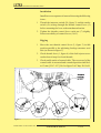
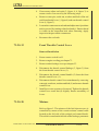
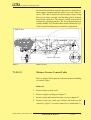
SERVICE MANUAL EXTRA 330LX
61-20-00
CONTROLLING
The propeller blade pitch change is conducted by a governor
(refer to Figure 1). Once an engine rotational speed is
selected it will be held constant independent of airspeed or
power variations.
The governor itself is actuated via a vernier control cable
ending on the left side of the rear cockpit (blue control knob;
1, figure 1 & 8, figure 2). This cable is routed on the left side
of the fuselage, penetrates the firewall, the rear engine
baffles and is then routed to the governor. The cable is
attached at its front end to the engine by a clamp block and in
the cockpit area to the steel tube structure by self-clinching
plastic tiedown straps. The RPM vernier control unit is
mounted to a fuselage bracket. The firewall and engine baffle
penetrations are covered with clamp sheets. The firewall
penetration (2, figure 1) is additionally sealed with PRC812 (Products Research & Chemical Corp., USA) firewall
sealant.
Mechanical stops for low pitch and high pitch limit the pitch
change level. In case the oil pressure is lost, the installed
counterweights automatically force the blades into high
pitch.
Side View
RPM Vernier control cable
Governor
2
Figure 1
PAGE DATE: 24.
1. March
November
2011 2011
Controlling
TEMPORARY REVISION
N° 0E702-TR-01-20111124
CHAPTER
PAGE
61
5
SERVICE MANUAL EXTRA 330LX
Left View
6
or
2
3
4
5
Engine
Baffle
1
11
Engine
Firewall
10
Cockpit
6
7
5 mm
9
Figure 2
PAGE DATE: 24.
1. March
November
2011 2011
8
RPM Vernier Control Cable Installation
TEMPORARY REVISION
N° 0E702-TR-01-20111124
CHAPTER
PAGE
61
6
SERVICE MANUAL EXTRA 330LX
61-20-01
Governor
One of the following governors is installed:
MT-Propeller P-880-41, preset for a max. 2600 rpm
MT-Propeller P-880-5, preset for a max. 2700 rpm
Woodward A-210988, preset for a max. 2700 rpm
Refer to the MT-Propeller Operation- and Installation Manual
E-1048 for further information.
NOTE
The lever position of the governor actuator is preset.
Do not change this position.
61-20-02
RPM Vernier Control Cable
Refer to chapter 20 for general information about handling
of control cables.
Removal
PAGE DATE: 24.
1. March
November
2011 2011
1
Ensure master switch is off.
2
Remove engine upper cowling per Chapter 71.
3
Remove main and bottom fuselage cover per Chapter 53.
4
Remove cotter pin, castle nut, washers and bolt from the
rod end (1, Figure 2) to governor control lever (2)
attachment.
5
Loosen counter nut and remove the rod end (1) from the
vernier control cable (6).
6
Remove rod end counter nut and vernier control cable
protective swivel and wiper seal (4).
7
Remove clamp block (5) attachment bolt(s).
8
Remove clamp block from the vernier control cable (6).
9
Remove 2 bolts of the clamp sheet attachment positioned
at the rear engine baffle break through (11). Disconnect both
clamp sheets and contained plastic guidance from the engine
baffle.
TEMPORARY REVISION
N° 0E702-TR-01-20111124
CHAPTER
PAGE
61
7
SERVICE MANUAL EXTRA 330LX
10
Remove 2 bolts of the clamp sheet attachment positioned
at the firewall break through (10). Disconnect clamp sheet
and contained plastic guidance from the rear side of the
firewall.
11
Mark vernier control cable routing and remove the selfclinching plastic tiedown straps in the cabin area.
12
Remove attachment nut (9) and washer of the vernier control
unit (7).
13
To remove vernier control unit from its bracket, pull the
unit slightly aft (about 15cm [0.5ft]) and then to the LH
outside direction.
14
Pull complete vernier control cable (6) aft to remove from
aircraft. Secure clamp sheets.
Installation
Install in reverse sequence of removal observing the following
items:
1
Thread the respective clamp sheets and plastic guidance on
the vernier control cable before penetrating the firewall and
the rear engine baffle.
2
Install rod end to the vernier control cable terminal. Ensure
thread of control cable terminal is visible in the inspection
hole.
3
Renew the sealing of the firewall break through at the engine
side of the firewall. Use PRC-812 (Products Research &
Chemical Corp., USA) firewall sealant.
4
Tighten the castle nut slightly. Ensure movability of governor
control lever (2).
Rigging
PAGE DATE: 24.
1. March
November
2011 2011
1
Move vernier control knob (8, Figure 2) to the foremost
position.
2
Check that the travel stop at the governor control lever is
reached, and the over-travel of 5mm [3/16"] (tolerance +/-1
mm [1/32"]) is ensured at the rpm control knob (see figure
2).
TEMPORARY REVISION
N° 0E702-TR-01-20111124
CHAPTER
PAGE
61
8
SERVICE MANUAL EXTRA 330LX
PAGE DATE: 24.
1. March
November
2011 2011
3
Check full travel.
4
If necessary adjust rod end (1, figure 2) by the following
steps:
a
Remove cotter pin, castle nut, washers and bolt from the
rod end (1) to governor control lever (2) attachment.
b
Loosen the counter nut and adjust rod end (1) by turning.
Ensure thread is visible in the inspection hole when
fastening. Apply inspection lacquer on the counter nut.
c
Reconnect the rod end (1) to the governor control lever (2).
TEMPORARY REVISION
N° 0E702-TR-01-20111124
CHAPTER
PAGE
61
9
MAINTENANCE MANUAL EXTRA 330LX
Table of Contents
Chapter/Figure
Title
73-20-00
73-20-10
Figure 1
73-20-11
Figure 2
73-20-12
Figure 3
Figure 4
73-20-12
73-20-20
Figure 5
73-20-21
Figure 6
Figure 7
CONTROLLING . . . . . . . . . . . . . . . . . . . . . . . . . . . . . 3
Throttle . . . . . . . . . . . . . . . . . . . . . . . . . . . . . . . . . . . . . 3
Throttle Control . . . . . . . . . . . . . . . . . . . . . . . . . . . . . . 3
Throttle Control Cable . . . . . . . . . . . . . . . . . . . . . . . . . 4
Firesleeve Length . . . . . . . . . . . . . . . . . . . . . . . . . . . . . 5
Rear Throttle Control Lever . . . . . . . . . . . . . . . . . . . . . 6
Throttle Control Levers . . . . . . . . . . . . . . . . . . . . . . . . 6
Throttle Control Cable Rigging . . . . . . . . . . . . . . . . . . 7
Front Throttle Control Lever . . . . . . . . . . . . . . . . . . . . . 8
Mixture . . . . . . . . . . . . . . . . . . . . . . . . . . . . . . . . . . . . . 8
Mixture Control . . . . . . . . . . . . . . . . . . . . . . . . . . . . . . 9
Mixture Vernier Control Cable . . . . . . . . . . . . . . . . . . . 9
Over-travel at Mixture Control Unit, . . . . . . . . . . . . . 11
Mixture Vernier Control Cable Rigging . . . . . . . . . . . 12
73-30-00
73-30-10
Figure 8
73-30-11
73-30-12
73-30-15
INDICATING . . . . . . . . . . . . . . . . . . . . . . . . . . . . . . .
Fuel Pressure. . . . . . . . . . . . . . . . . . . . . . . . . . . . . . . .
Fuel Pressure Sense Line . . . . . . . . . . . . . . . . . . . . . .
Fuel Pressure Gauge . . . . . . . . . . . . . . . . . . . . . . . . . .
Sense Line . . . . . . . . . . . . . . . . . . . . . . . . . . . . . . . . . .
Fitting . . . . . . . . . . . . . . . . . . . . . . . . . . . . . . . . . . . . .
PAGE DATE: 24.
1. March
November
2011 2011
TEMPORARY REVISION
N° 0E702-TR-01-20111124
CHAPTER
PAGE
13
13
14
14
14
15
73
2
MAINTENANCE MANUAL EXTRA 330LX
73-20-00
CONTROLLING
73-20-10
Throttle
Refer to figure 1. The throttle is controlled by means of the
throttle control levers located on the left side of the cockpit.
These levers are interconnected by the throttle control
linkage. The throttle control levers transfer their movements
to the throttle by means of the throttle control cable. This
cable is routed on the left side of the fuselage, penetrates the
firewall and is then routed centrally below the exhaust
muffler to the throttle. In the engine compartment this cable
is covered with a fire sleeve. The cable is attached to the
fuselage using clamp blocks at its ends, self-clinching plastic
tiedown straps in the cockpit area, and a cushioned clamp at
the exhaust muffler. Rod ends at both terminals of the
control cable serve as a means for rigging. The fire wall
penetration is sealed with PRC-812 (Products Research &
Chemical Corp., USA) firewall sealant and covered with
clamp sheets.
Side View
Rear throttle control lever
Front throttle control lever
Throttle control linkage
Throttle control cable
Figure 1
PAGE DATE: 24.
1. March
November
2011 2011
Throttle Control
TEMPORARY REVISION
N° 0E702-TR-01-20111124
CHAPTER
PAGE
73
3
MAINTENANCE MANUAL EXTRA 330LX
73-20-11
Throttle Control Cable
Refer to chapter 20 for general information about handling
of control cables.
Removal
1
Ensure master switch is off.
2
Remove engine cowling per chapter 71.
3
Remove main fuselage cover per chapter 53.
4
Remove cotter pin, castle nut, washers and bolt from the
rod end (2, figure 4) to throttle actuator (1) attachment.
5
Loosen counter nut and remove the rod end from the throttle
control cable.
6
Remove rod end counter nut and throttle control cable
protective swivel and wiper seal.
7
Remove clamp block (3) attachment bolt(s).
8
Remove clamp block from the throttle control cable.
9
Remove cushioned clamp (4) .
10
Cut safety wires and remove fire sleeve from the throttle
control cable.
11
Remove 4 bolts and firewall sealant of the clamp sheets
(figure 2) positioned at the firewall break through.
12
Mark throttle control cable routing and remove the selfclinching plastic tiedown straps in the cabin area.
13
Remove cotter pin, castle nut, washers and bolt and remove
the rod end (6, figure 3) from the throttle control lever (5).
14
Loosen counter nut and remove the rod end from the throttle
control cable.
15
Remove rod end counter nut and throttle control cable
protective swivel and wiper seal.
16
Remove clamp block (4) attachment bolt(s).
17
Remove clamp block from the throttle control cable (8).
18
Pull complete throttle control cable aft to remove from
aircraft. Secure clamp sheets.
PAGE DATE: 24.
1. March
November
2011 2011
TEMPORARY REVISION
N° 0E702-TR-01-20111124
CHAPTER
PAGE
73
4
MAINTENANCE MANUAL EXTRA 330LX
Installation
Install in reverse sequence of removal observing the following
items:
1
Install throttle control cable, ensure distance between clamp
sheet and clamp block is 705 mm (refer to figure 2).
Figure 2
PAGE DATE: 24.
1. March
November
2011 2011
Firesleeve Length
2
Renew the sealing of the firewall break through at the engine side of the firewall. Use PRC-812 (Products Research
& Chemical Corp., USA) firewall sealant. Let the sealant
slightly cure before thightening the clamp sheet attachment
bolts. This will strengthen the clamping.
3
Install both rod ends to the control cable terminals. Ensure
thread of control cable terminal is visible in the rod end
inspection hole.
4
Tighten the castle nuts at both rod end attachment bolts
slightly. Ensure movability of levers.
TEMPORARY REVISION
N° 0E702-TR-01-20111124
CHAPTER
PAGE
73
5
MAINTENANCE MANUAL EXTRA 330LX
73-20-12
1
Rear Throttle Control Lever
2
3
5
5a
5b
4
9
Figure 3
Throttle Control Levers
Removal
PAGE DATE: 24.
1. March
November
2011 2011
1
Ensure master switch is off.
2
Remove engine cowling per chapter 71.
3
Remove main fuselage cover per chapter 53.
4
Remove cotter pin, castle nut, washers and bolt (6, figure 3)
and the throttle control linkage (3) from the throttle control
lever (5).
5
Pull the smoke switch (5a, if installed) out of the throttle
lever handle and disconnect switch wiring.
6
Remove intercom switch (5b) attachment nut. Remove selfclinching plastic tiedown straps of related wiring. Pull the
intercom switch out of the throttle control lever grip.
7
Disconnect throttle control lever attachment by removing
cotter pin, castle nut, washers and bolt (7). Remove throttle
control lever.
TEMPORARY REVISION
N° 0E702-TR-01-20111124
CHAPTER
PAGE
73
6
MAINTENANCE MANUAL EXTRA 330LX
Installation
Install in reverse sequence of removal observing the following
items:
1
Thread the intercom switch (5b, figure 3) and the smoke
switch (5a) wiring through the throttle control lever (5)
before mounting the lever to the attachment bracket.
2
Tighten the throttle control lever castle nut (7) slightly.
Ensure movability of control levers (1 & 5).
Rigging
1
Move the rear throttle control lever (5, figure 3) in idle
position parallel to the adjoining fuselage structure steel
tube (as shown in figure 3).
2
Check throttle lever (1, figure 4) of the fuel injector servo
reached travel stop for closed throttle.
3
Check usable stroke of control cable. The over-travel of the
control cable in retracted and extended position shall be 8
to 13 mm [5/16"-1/2"]. Ref. to figure 2 of Chap. 20-10-09.
2
1
3
4
Figure 4
PAGE DATE: 24.
1. March
November
2011 2011
Throttle Control Cable Rigging
TEMPORARY REVISION
N° 0E702-TR-01-20111124
CHAPTER
PAGE
73
7
MAINTENANCE MANUAL EXTRA 330LX
4
If necessary adjust rod ends (2, figure 4; 6, figure 3) to
ensure correct over-travel by the following steps:
a
Remove cotter pin, castle nut, washers and bolt of the rod
end from throttle lever (1, figure 4) and rear throttle control
lever (6, figure 3).
b
Loosen the counter nut at rod ends and adjust travel positions
and over travel by turning related rod end(s). Ensure thread
is visible in the inspection hole when fastening. Apply
inspection lacquer on the counter nut.
c
Reconnect the rod ends.
73-20-12
Front Throttle Control Lever
Removal/Installation
73-20-20
1
Ensure master switch is off.
2
Remove engine cowling per chapter 71.
3
Remove main fuselage cover per chapter 53.
4
Disconnect the throttle control linkage (3, figure 3) from
the front throttle control lever (1).
5
Disconnect the throttle control handle (2) from the front
throttle control lever (1).
6
Disconnect throttle control lever attachment by removing
cotter pin, castle nut, washers and bolt (9) and remove throttle
control lever.
7
Install in reverse sequence of removal. Tighten the throttle
control lever castle nut (9) slightly. Ensure movability of
levers.
Mixture
Refer to figure 5. The mixture of the fuel injector servo is
controlled by means of the vernier mixture control cable
located on the left side of the cockpit (red control knob).
This cable is routed on the left side of the fuselage, penetrates
PAGE DATE: 24.
1. March
November
2011 2011
TEMPORARY REVISION
N° 0E702-TR-01-20111124
CHAPTER
PAGE
73
8
MAINTENANCE MANUAL EXTRA 330LX
the firewall and is then routed to the mixture control lever.
In the engine compartment this cable is covered with a fire
sleeve. The cable is attached to the fuselage using a clamp
block at its front end and self-clinching plastic tiedown
straps in the cabin area. The mixture vernier control unit is
mounted to a fuselage bracket. The fire wall penetration is
sealed with PRC-812 (Products Research & Chemical Corp.,
USA) firewall sealant and covered with a clamp sheet.
Side View
2
Mixture control cable
Figure 5
Mixture Control
73-20-21
Mixture Vernier Control Cable
Refer to chapter 20 for general information about handling
of control cables.
Removal
PAGE DATE: 24.
1. March
November
2011 2011
1
Ensure master switch is off.
2
Remove engine cowling per chapter 71.
3
Remove main and bottom fuselage cover per chapter 53.
4
Remove cotter pin, castle nut, washers and bolt from the
rod end (2, figure 7) to mixer control lever attachment (3).
TEMPORARY REVISION
N° 0E702-TR-01-20111124
CHAPTER
PAGE
73
9
MAINTENANCE MANUAL EXTRA 330LX
5
Loosen counter nut and remove the rod end (2) from the
mixture control cable.
6
Remove rod end counter nut and mixture vernier control
cable protective swivel and wiper seal.
7
Remove clamp block (1) attachment bolt(s).
8
Remove clamp block (1) from the vernier mixture control
cable.
9
Cut safety wires and remove fire sleeve from vernier mixture
control cable.
10
Remove 2 bolts of the clamp sheet attachment positioned
at the firewall break through (2, figure 5). Disconnect clamp
sheet and contained plastic guidance from the rear side of
the firewall.
11
Mark mixture vernier control cable routing and remove the
attachment self-clinching plastic tiedown straps in the cabin
area.
12
Remove attachment nut and washer of the mixture control
unit (1, figure 5).
13
To remove mixture vernier control unit from its bracket,
pull the unit slightly aft (about 15cm [0.5ft]) and then to the
LH outside direction.
14
Pull complete mixture vernier control cable aft to remove
from aircraft. Secure clamp sheet.
Installation
Install in reverse sequence of removal observing the following
items:
PAGE DATE: 24.
1. March
November
2011 2011
1
Thread the respective rear clamp sheet and plastic guidance
on the mixture control cable before penetrating the firewall.
2
Install rod end to the vernier mixture control cable terminal.
Ensure thread of control cable terminal is visible in the
inspection hole.
TEMPORARY REVISION
N° 0E702-TR-01-20111124
CHAPTER
PAGE
73
10
MAINTENANCE MANUAL EXTRA 330LX
3
Renew the sealing of the firewall break through (2, figure
5) at the engine side of the firewall. Use PRC-812 (Products Research & Chemical Corp., USA) firewall sealant.
4
Tighten the castle nut slightly. Ensure movability of mixer
control lever (3, figure 7).
Rigging
1
Move mixture control knob to the foremost position.
2
Check that the travel stop at the mixture control lever is
reached, and the over-travel of 5mm [3/16"] (tolerance +/-1
mm [1/32"]) is ensured at the mixture control knob (see
figure 6).
Figure 6
PAGE DATE: 24.
1. March
November
2011 2011
Over-travel at Mixture Control Unit,
3
Check full travel.
4
If necessary adjust rod end (2, figure 7) by the following
steps:
a
Remove cotter pin, castle nut, washers and bolt from the
rod end (2) to mixer control lever (3) attachment.
b
Loosen the counter nut and adjust rod end (2) by turning.
Ensure thread is visible in the inspection hole when
fastening. Apply inspection lacquer on the counter nut.
c
Reconnect the rod end (2) to the mixture control lever (3).
TEMPORARY REVISION
N° 0E702-TR-01-20111124
CHAPTER
PAGE
73
11
MAINTENANCE MANUAL EXTRA 330LX
or
3
Figure 7
PAGE DATE: 24.
1. March
November
2011 2011
2
1
Mixture Vernier Control Cable Rigging
TEMPORARY REVISION
N° 0E702-TR-01-20111124
CHAPTER
PAGE
73
12


![U.S. Version [Last Updated on: Jun 13th, 2014]](http://vs1.manualzilla.com/store/data/005873845_1-0370c7761d3b42576ec2ae1fd24c9e75-150x150.png)