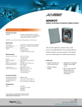
Download SpeedDome Ultra Drone Installation 8000-1941-01
Transcript
SpeedDome® Ultra
Drone Installation
Main Components
Overview
The drone consists of a housing and an eyeball
assembly—yoke, yoke brackets, slot cover, and cable
assembly—that “twist locks” onto a mounting base
(Figure 2).
The SpeedDome Ultra Drone is an Ultra housing that
can be outfitted with a fixed camera. The drone looks
like a fully functional dome camera and can be used as
a deterrent.
Figure 1. SpeedDome Ultra Drone,
01RDULTRA
Installation Procedures
Detailed mounting instructions, using various mounting
techniques, are presented step-by-step in the
SpeedDome Ultra Camera Dome Installation and
Service Manual (8000-1362-01). To install the drone to
a hard ceiling using the install kit provided, see below.
0.66 kg
(1.45 lbs)
Installing Drone to Sheet Rock
and Wood Beams
205 mm
(8 in.)
The drone base can be mounted directly to a sheet rock
ceiling or wood beam by following the instructions
below.
Install Kit Required
Kit, Installation, Ultra Drone (0351-1309-01)
120 mm
(4.7 in.)
Anchor toggle
Screw, STAP, AB, 4.2X32 PHP
Washer, Flat, M4
Bracket, Base Mounting
Screw, 1/4-20x3/8,” PHP
Screw, PH, M3X-8, PHP, SS
Washer, 1/4, Flat
2
2
2
2
1
6
1
2880-0073-01
5810-4091-120
5842-0300-020
0500-7193-01
2802-7407-65
5801-1051-120
2848-8100-07
Figure 2. SpeedDome Ultra Drone—Exploded View
Tape, PET, 3200-0309-01
Slot cover (with lens port),
0500-6709-01
Yoke Bracket, 0500-7254-01 (2)
Housing, 0500-7255-01
Skirt,
0500-6710-01
Cap, 0500-7256-01
Dot, 3200-0027-04
Yoke,
0500-7258-01
Video cabling, 06003-0101-01;
Power cabling, 0650-1993-01
(including cable ties, 6009-0006)
Base, 0500-7257-01
Pan Gear Bearing Assy,
2510-0040-02
Lens carriage
bearing assy,
2510-0038-02 (2)
Tape, PET, 3200-0309-01
Screws (3), M3X45 PHP,
5801-1141-111
Slot cover (without lens port),
0500-6709-02
SpeedDome is a registered trademark of Sensormatic Electronics Corporation.
8000-1941-01, Rev. B1
CCTV PRODUCTS
1
1. Place the base against the ceiling and mark
locations for two mounting holes.
Use Figure 3 for sheet rock; Figure 4 for wood. If
mounting to sheet rock, also mark the location for the
cable access hole.
6. Attach the dome to the base.
Align the dot on the inside of the base with the target
on the cap of the dome, then mate the dome to the
base and turn it clockwise until you hear a click.
Figure 5. Attaching the dome to its base
2. Drill holes.
Sheet rock: Drill two 3/8-inch holes for plastic
anchors. Drill one 3/4-inch hole for cable access.
Wood: Drill two 1/8-inch holes for the mounting
screws. If wood covers the cable access hole, drill
one 3/4-inch hole for cable access.
Dot on
inside
surface
3. To enable you to properly align the dome
(cap) and base in step 6, align the target on
the outside of the cap with the visible dot
on the inside surface of the base.
L A TCH
Cap
4. Mount the base to the ceiling.
Sheet Rock: Install plastic anchors [a]. Then place
washers [b] onto screws [c] and insert them into the
anchors.
Wood: Place washers [b] onto screws [c] and insert
them into the wood.
5. Feed cables through the base, letting them
hang loose within the drone.
Figure 3. Surface mounting to sheet rock
7. If installing a camera locally, mount the
camera assembly to the yoke using the 1/420x3/8” screw.
Camera clearance inside yoke assembly: H=55mm,
W=60mm, D=90mm. Camera weight is not to exceed
250g (0.55 lb).
Figure 6. Securing the camera assembly
c
a
Yoke
b
Drone
Mounting screw
secures camera
assy
Cable
Access
Hole
8. Connect the video cables.
Mate the BNC connectors from the video cables.
Figure 4. Surface mounting to wood beams
Figure 7. Video cable connections
c
Cable
Access
Hole
2
1
b
J Box
cable
9. Connect the power cables.
Connect the 6-pin power cables.
Figure 8. Power cable connections
BLK 1
4
2
5
3
6
RED
WHT
2
CCTV PRODUCTS
Camera
cable


