1
www.think3dprint3d.com
Mendel90 Laser Cut Kit
Assembly Instructions
1.
Acknowledgements
The Mendel 90 Lasercut design is based on the Mendel90 design by Chris Palmer (Nophead) and
this build manual uses some of the original Mendel90 build manual where the assembly process is
similar.
2.
License
This manual and the source code for the Mendel 90 LC are both licensed under the GPL v2.0. It is
based on work by Nophead which is licensed under the GPL v2.0.
3.
Changes
19/10/13 – Integrating initial customer feedback
08/10/13 – Final review prior to first publication.
07/10/13 – Added acrylic enclosure section.
06/10/13 – New X end design pictures added.
03/10/13 – Beta tester feedback integrated.
27/09/13 – Initial version.
M90LC Manual
2 of 70
V0.4-20131016
4.
Table of Contents
1.
2.
3.
4.
5.
6.
7.
Acknowledgements .............................................................................................................. 2
License................................................................................................................................. 2
Changes............................................................................................................................... 2
Table of Contents ................................................................................................................. 3
Kit Contents.......................................................................................................................... 5
General Build Tips ................................................................................................................ 6
Tools..................................................................................................................................... 8
Required ................................................................................................................................. 8
Recommended ........................................................................................................................ 8
8. X-Axis Sub-Assemblies ........................................................................................................ 9
X-idler...................................................................................................................................... 9
X-motor ................................................................................................................................. 10
1.3 X-carriage-fan ................................................................................................................. 14
1.4 X-carriage........................................................................................................................ 16
9. Y-Axis Sub-Assemblies ...................................................................................................... 18
Y-idler .................................................................................................................................... 18
Y-motor ................................................................................................................................. 20
Y-carriage .............................................................................................................................. 21
Y-heatshield .......................................................................................................................... 23
10. Z-Axis Sub-Assemblies ................................................................................................... 24
Z-motors................................................................................................................................ 24
Z-top-brackets ....................................................................................................................... 25
Z-endstop .............................................................................................................................. 26
11.
Extruder Sub-Assemblies................................................................................................ 27
E-motor ................................................................................................................................. 27
Extruder ................................................................................................................................ 29
12. Frame Assembly ............................................................................................................. 32
13. Y-Axis Assembly ............................................................................................................. 38
14. Z Axis Assembly.............................................................................................................. 45
15. X-Axis assembly ............................................................................................................. 47
16. Electronics Assembly ...................................................................................................... 51
17. Firmware and Software ................................................................................................... 55
Marlin Firmware .................................................................................................................... 55
Arduino IDE ........................................................................................................................... 55
Pronterface ........................................................................................................................... 55
Slic3r ..................................................................................................................................... 56
18. Testing and Commissioning ............................................................................................ 57
Power up ............................................................................................................................... 57
Limit switches ........................................................................................................................ 57
Motors ................................................................................................................................... 58
Heaters ................................................................................................................................. 58
19. Calibration ...................................................................................................................... 59
Firmware setup ..................................................................................................................... 59
Nozzle-bed alignment 1 – X axis levelling ............................................................................. 59
Nozzle-bed alignment 2 – Y axis levelling.............................................................................. 60
Setting the Z axis dimension ................................................................................................. 60
Extruder E-steps calibration. ................................................................................................. 62
Calibration objects. ................................................................................................................ 62
Fitting the fan ........................................................................................................................ 63
20. Acrylic Enclosure Assembly ............................................................................................ 64
Side panels ........................................................................................................................... 64
Back panel ............................................................................................................................ 65
Top Panel .............................................................................................................................. 65
M90LC Manual
3 of 70
V0.4-20131016
Doors .................................................................................................................................... 66
21. Operating Instructions ..................................................................................................... 68
Heated Bed ........................................................................................................................... 68
Changing filament ................................................................................................................. 68
Removal ................................................................................................................................ 68
Insertion ................................................................................................................................ 69
Different types of filament ...................................................................................................... 69
Cleaning the hobbed bolt ...................................................................................................... 69
PID Autotune ......................................................................................................................... 69
M90LC Manual
4 of 70
V0.4-20131016
5.
Kit Contents
The kit contains the following items, Detailed lists (Bills of Material/BOMs) are included in each
subsection of the manual
Laser cut frame and aluminium base channels
Printed Parts
Fasteners
Bearings
Rods
Motors
Hot end and heated print bed.
Electronics and wiring, including LCD display
Power supply
Starter PLA filament pack (note that it will vary from that pictured above)
Laser cut acrylic enclosure (optional extra)
M90LC Manual
5 of 70
V0.4-20131016
6.
General Build Tips
The build is broken down into sub-assemblies that can be worked on sequentially by one
person, or in parallel if there is more than one person building.
To make it easier to find the relevant section, the sub-assembly sections are in the order X,
Y, Z, and E. This does not mean they have to be tackled in this order.
Once the sub-assemblies are completed, the suggested assembly order is Frame, Y-axis,
Z-axis, X-axis and Electronics
Looking at the printer from the front, X is left / right. Y is backwards / forwards. Z is up /
down. The origin X=0, Y=0, Z=0 is at the front left-hand corner of the print bed glass,
touching the glass
Bar lengths: The longest and shortest bars are the Y bars. Of the two pairs left, the longer
ones are the X axis and the shorter ones the Z axis.
The longer belt is for X and the shorter one is for Y.
De-grease the rods that come with packing grease. (You will need to lubricate them again
after assembly).
All screws have a plain washer where they meet the plastic, to spread the load and prevent
the plastic being chewed up by the rotation of the screw head. Most plastic parts have a
captive nyloc nut to prevent them vibrating loose. We supply our kits with all captive nuts
already inserted to speed up assembly. In case any of them should fall out, plastic parts are
supplied bagged. You should carefully check the bag for any loose nuts and add them to
the loose nuts supplied, ready for when they are needed.
You may have some washers, nuts and smaller screws left over at the end of the assembly.
This is because we provide spares of the small easy-to-lose items.
The bar clamps should not be over tightened, i.e. do not close the gap fully or the parts
could break. The Y and Z bars only need a light clamping force because the only force
trying to slide them is the bearing friction. Washers tend to have a smooth side and a side
with a burr from being stamped out. Make sure the smooth side faces bearings and belts.
The laser-cutting process does not produce perfectly square 90° cuts because the cutting
beam is focussed to a point and so makes a tapered cut. This means that some parts will
have a “right” side and a “wrong” side. This is particularly true of the Z-motor brackets
where the projecting 22mm diameter boss or spigot of the motor should only fit easily from
one side of the top plates. The square nuts used for assembly of the MDF frame and
acrylic cabinet will also fit into their slots (and fall out of them) much more easily from one
side that the other.
Zip-ties (cable ties) are used for securing cables and also linear bearings. Only those used
for linear bearings are listed in the Bill of Materials (BOM) for each section, but we supply
enough for all cable management and a few spares as well.
Ribbon clamp notation is <number of wires>_<hole size>. There are three lengths: the
short ones are 14 way for the X axis, the medium ones are 20 way for the Z axis and the
long ones are 26 way for the bed. An N suffix denotes with nut traps. B denotes no slot.
M90LC Manual
6 of 70
V0.4-20131016
M90LC Manual
7 of 70
V0.4-20131016
7.
Tools
Required
Spanners: 5.5mm (¼ drive socket supplied), 7mm & 13mm.
Allen keys: 1.5mm, 2mm, 2.5mm, 3mm - Supplied
PZ 1 Pozi-drive screw driver.
Digital callipers
Recommended
M90LC Manual
Multi-meter with thermocouple attachment
Dial gauge
Wire brush
Consumables
Lithium/PTFE grease, glass cleaner (acetone recommended), lint free wipes.
8 of 70
V0.4-20131016
8.
X-Axis Sub-Assemblies
X-idler
BOM
Category
Mechanical
Mechanical
Printed
Printed
Fasteners
Fasteners
Fasteners
Fasteners
Fasteners
Fasteners
Fasteners
Fasteners
Description
Bearing, ball, 624-ZZ
Bearing, linear, LM8UU
X idler bracket
X_end_clamp
M3x20 socket cap screw
M3 form A flat washer
M3 nyloc nut
M4x45 socket cap screw
M4 form A flat washer
M4 x 20 x 1.25 Penny washer
M4 nyloc nut
M5 brass full nut
Qty
2
2
1
2
8
8
8
1
2
2
1
1
Comments
Pre-fitted
Pre-fitted
Pre-fitted
Pre-fitted
Method
1. Fit the end clamps to the idler bracket, rounded corners facing outwards, using the M3 x 20
socket cap screws with flat washers between the screw head and the plastic. Ensure the
screws engage in the nylon inserts in the pre-fitted nyloc nuts but do not tighten them fully.
Make the washer and bearing kebab on the long M4 bolt that forms the idler axle, but leave
it loose to allow the X bars to be inserted later.
M90LC Manual
9 of 70
V0.4-20131016
X-motor
BOM
Category
Electrical
Electrical
Mechanical
Mechanical
Mechanical
Sundries
Sundries
Printed
Printed
Printed
Printed
Printed
Printed
Printed
Printed
Fasteners
Fasteners
Fasteners
Fasteners
Fasteners
Fasteners
Fasteners
Fasteners
Fasteners
Fasteners
Fasteners
Description
Extruder/X-motor wiring loom
Micro switch end stops
Bearing, linear, LM8UU
Timing pulley T2.5-16T, M4 grub screw
Stepper motor NEMA17 high-torque 44Ncm
Polypropylene strip 270 x 33 x 0.5
Polypropylene strip 400 x 18 x 0.5
d_shell
d_shell_lid
ribbon_clamp_14_33
ribbon_clamp_14_33NB
ribbon_clamp_20_33
x_motor_bracket
x_motor_ribbon_bracket
X_end_clamp
M3x10 socket cap screw
M3x16 socket cap screw
M3x20 socket cap screw
M3x45 socket cap screw
M3 form A flat washer
M3 external shake proof washer
M3 nyloc nut
No 2 x 1/2 Pozi pan S/T screw
M2.5 flat washer x 5.9 x 0.5
Nitrile O-ring 2.5 x 1.6
M5 brass full nut
Qty
1
1
2
1
1
1
1
1
1
1
1
1
1
1
2
2
6
10
2
19
3
14
4
4
2
1
Comments
Pre-fitted
Pre-fitted
Pre-fitted
17?
2?
Pre-fitted
Pre-fitted
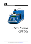
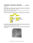
Illustration
10
M90LC Manual
10 of 70
V0.4-20131016
Method
1. Insert the D-connector into the d_shell printed part in the orientation shown below.
2. Secure the connector by screwing on the d_shell_lid with two No2 x 13mm posi pan selftapping screws with M2.5 washers.
3. Clamp down the cable with the thinnest polypropylene strip under it (against the D shell)
using the ribbon_clamp_14_33NB, M3 x 16mm cap screws and M3 washers (from the
underside).
4. Complete the D connector by adding M3 x 20mm socket cap screws and flat washers and
then secure them in place with the rubber O rings.
5. Fit the pulley to the motor shaft so that 3mm of the shaft protrudes beyond the pulley. Don’t
over tighten the grub screw.
6. Fit the motor with the pre-fitted ribbon bracket at the top and secure it to the front of the
motor bracket with two M3 x 10 socket cap screws, star washers and plain washers
7. Motors have a ± 1mm tolerance on their length so the bracket at the back may have up to
2mm clearance. We check this and supply extra washers if needed. If there is a gap then
M90LC Manual
11 of 70
V0.4-20131016
pack it with M3 washers using between 1 and 5. Screw the M3 x 45mm cap screw through
the hole in bracket, the washers (if fitted) and into the motor. The head of the screw will
hold the back corner of the motor in the bracket
8. Clamp the 14 way cable and the thinner polypropylene strip in the ribbon clamp on the top
of the X motor bracket with the red edge at the top using the ribbon_clamp_14_33, M3 x
16mm socket cap screws and M3 washers. Form the cable and strip into a loop as shown
in the picture below before tightening the clamp fully. This is necessary because the cable
needs to be a bit longer than the strip to go round the outside of the curve.
9. Clamp the full 20 way part of the cable onto the x_motor_ribbon_bracket at the rear of the
motor with the second polypropylene strip on top using the ribbon_clamp_20_33 with M3 x
16mm socket cap screws and M3 washers..
10. It is recommended to add loops of sticky tape (not provided) to fasten the middle of each
cable to the middle of its cable strip.
11. Insert the eight M3 x20mm bar clamp socket cap screws as described above for the X idler
assembly.
12. Pass the two x-endstop wires with spade connectors fitted out through the hole for the limit
switch. Plug the spade connectors securely onto the switch using the top and bottom pins
M90LC Manual
12 of 70
V0.4-20131016
(it does not matter which way round they are) and then mount it with two No2 x 13mm pozi
pan self-tapping screws with M2.5 washers. N.B. The micro switch must be oriented
with the button towards the top. Bend the bottom pin upwards slightly so the spade
connector clears the head of the nearest socket cap screw.
13. Pass the X-motor cable down through around the motor and plug it into the connector
(make sure the plug is the right way round and do not try to force it).
M90LC Manual
13 of 70
V0.4-20131016
1.3 X-carriage-fan
BOM
Category
Electrical
Printed
Printed
Fasteners
Fasteners
Fasteners
Description
Extruder fan 60mm x 15mm
x_carriage_fan_bracket
x-carriage_fan_duct
M4x30 socket cap screw
M4 form A flat washer
M4 nyloc nut
Qty Comments
1
Modified, see below
1
1
4
4
4
Pre-fitted
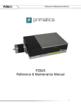
Method
1. The fan is fitted with the label downwards. Examine the top of the fan and identify the edge
where the rim has been cut away (opposite side to the cable exit). This is the side on which
the fan bracket is mounted.
M90LC Manual
14 of 70
V0.4-20131016
2. Assemble as shown below with the fan label downwards and the wires exiting in the front,
nearest the leftmost screw in the picture.
M90LC Manual
15 of 70
V0.4-20131016
1.4 X-carriage
BOM
Category
Mechanical
Mechanical
Sundries
Printed
Printed
Printed
Printed
Fasteners
Fasteners
Fasteners
Fasteners
Fasteners
Fasteners
Description
Bearing, linear, LM8UU
T2.5 timing belt X=860mm
Zip ties 120 long
x_belt_clamp
x_belt_grip
x_belt_tensioner
x-carriage
M3x12 socket cap screw
M3x20 socket cap screw
M3x25 socket cap screw
M3 form A flat washer
M3 full nut
M3 nyloc nut
Qty
3
1
3
1
1
1
1
2
2
1
4
1
4
Comments
Pre-fitted
Pre-fitted
Pre-Fitted
Pre- Fitted
Method
M90LC Manual
16 of 70
V0.4-20131016
1. Insert the two M3 x 12mm screws and washers for the fan mount into the pre-fitted captive
nuts but leave loose.
2. Attach the X belt (longer of the two) to the left side x_belt_clamp (RHS in the picture above)
with the teeth facing upwards (downwards in the picture) and four complete teeth projecting
from the clamp. The teeth slot into the grip grooves in the clamp to help the orientation.
Clamp with the M3 x 20mm socket cap screw and washer.
3. Insert a M3 x 20mm socket cap screw for the belt tensioner into the pre-fitted captive nut
Holding the X-carriage with the bearings facing up so the two bearings are closest to you.
Pull the attached part of belt out to the right, then pass it underneath. Put one half-twist in
the belt away from yourself so the teeth also face away (to avoid them catching on the fan)
and the flat side is now facing up. Follow the belt around and pass the other end of the belt
through the gap above the tensioner (the teeth should be up).
4. Put the tensioning piece on the end of the screw with the flange towards the carriage. Then
double back the belt over the tensioner (as depicted in yellow above) and clamp it with the
x_belt_grip (with the teeth fitting in the grooves) and an M3 x 25mm cap screw and washer
with four complete teeth projecting.
5.
M90LC Manual
17 of 70
V0.4-20131016
9.
Y-Axis Sub-Assemblies
Y-idler
BOM
Category
Mechanical
Printed
Fasteners
Fasteners
Fasteners
Fasteners
Fasteners
Description
Bearing, ball, 624-ZZ
y-idler-bracket
M4x20 socket cap screw
M4x30 socket cap screw
M4 form A flat washer
M4 x 20 x 1.25 Penny washer
M4 nyloc nut
Qty Comments
2
1
1
1
5
2
2
1 pre-fitted
Method
M90LC Manual
18 of 70
V0.4-20131016
Assemble as shown. This is easiest done using a zip tie to assemble the stack in order and
then pull it tight to fit the stack into the idler body.
Once in straight the zip tie can be gently replaced with the long M4x30 mm bolt. Do not
forget to put M4 washers on the M4 bolt on both sides of the Y-idler.
Screw the M4x 20mm bolt with washer loosely into the captive M4 nut for the time being so
it does not get lost.
M90LC Manual
19 of 70
V0.4-20131016
Y-motor
BOM
Category
Mechanical
Mechanical
Electrical
Printed
Fasteners
Fasteners
Fasteners
Fasteners
Fasteners
Fasteners
Description
Stepper motor NEMA17 high-torque 44Ncm
Timing pulley T2.5-16T, M4 grub screw
Y-motor cable - 1.00 long
y-motor-bracket
M3x10 socket cap screw
M3 form A flat washer
M3 external shake proof (star) washer
M4x20 socket cap screw
M4 form A flat washer
M4 nyloc nut
Qty Comments
1
1
1
1
4
4
4
4
4
4
fitted
Method
1. Attach the pulley to the motor using the grub screw with about 3mm spare at the end, do not
over tighten the grub screw
2. Slide the motor into the gap as above with the plug on the left hand side as viewed facing the
shaft. Secure the motor in place using the 4 M3x 10mm screws with star and flat washers, loosely
at first then tightening them all evenly.
3. Loosely insert the M4 x 20 socket cap screws and washers into the captive nuts, so they are not
misplaced. The Y motor cable will be plugged in later.
M90LC Manual
20 of 70
V0.4-20131016
Y-carriage
BOM
Category
Mechanical
MDF
Printed
Printed
Printed
Printed
Printed
Fasteners
Fasteners
Fasteners
Sundries
Description
Bearing, linear, LM8UU
Laser-cut MDF y-carriage
y_bearing_mount
y-belt-anchors
y_belt_anchor_toothed
y_belt_clip
y_belt_clip_toothed
M3x16 socket cap screw
M3 form A flat washer
M3 nyloc nut
Zip ties 120 long
Qty
3
1
1
1
1
1
1
14
14
14
3
Comments
Pre-fitted
Pre-fitted
Pre-fitted
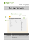
Method
This view is from the bottom of the bed. The cut out section goes at the back of the machine. The
nuts go on the bottom and the screw heads and washers on top. The majority of the holes should
M90LC Manual
21 of 70
V0.4-20131016
be on your right with the cut out section for the ribbon cable furthest from you.
1.
2. Fit the belt clamps loosely to their respective anchors using M3 x 16mm socket cap screws
and washers. The clamp with the tooth fits the anchor without teeth and vice versa. Fit the
anchors securely to the carriage using M3 x 16mm socket cap screw and washers. Note
that the anchor with the tooth is closest to the cut out section, the belt clamp with the tooth
at therefore at the front.
3. Bolt the linear bearing holders to the carriage using M3 x 16mm socket cap screws and
washers. Note that one side of the bearing holders has a tab to trigger the limit switch,
which must face forwards (that is, away from the ribbon clamp slot). Do not completely
tighten the M3x16 bolts at this stage, they are tightened after being aligned.
4. Align the two bearings on the left (right on the picture) by gently inserting a rod with a
twisting motion (to avoid knocking the balls out of the linear bearing) and lining up the tabs
with the edge of the board before tightening the bolts. Leave the third bearing loose.
M90LC Manual
22 of 70
V0.4-20131016
Y-heatshield
BOM
Category
Sundries
Sundries
Description
Corrugated cardboard 190 x 210 x 6
Aluminium foil tape 50 x 226 x 0.5
Qty Comments
1
Cut from packaging
1
Supplied
Method
The heat shield reduces the heat radiating downwards from the bed. This helps the heat bed to
warm up more quickly and reach a higher maximum temperature. The 6mm double-wall
corrugated cardboard used for printer kit boxes is used as a cheap and effective insulator and
aluminium foil tape on top reflects heat back towards the bed.
The shield can be retro-fitted but we find it is much quicker and easier to fit it as part of the main
build.
Cut a piece of cardboard to the size given in the BOM hold it against the Y-carriage and cut a
notch out of one long side to clear the ribbon cable clamps and a small notch to clear the front hex
pillar.
Cut a piece of aluminium tape about 250mm long, peel off the tape backing and apply to the
cardboard, wrapping the overlap underneath. Repeat with 4 more strips. We find it easiest to start
with a central strip from the notch at the back to the front, then to add 2 more strips with about 510mm overlap on each side of the central strip. Fold the edge overlaps underneath.
M90LC Manual
23 of 70
V0.4-20131016
10.
Z-Axis Sub-Assemblies
Z-motors
BOM
Category
MDF
MDF
Electrical
Electrical
Mechanical
Fasteners
Fasteners
Fasteners
Fasteners
Fasteners
Description
Z-motor bracket top
Z-motor bracket side
Z-motor cable L - 1.00m long
Z-motor cable R – 630mm long
Stepper motor NEMA17 high-torque 44Ncm
M3x12 socket cap screw
M3x16 socket cap screw
M3 form A flat washer
M3 external shake proof (star) washer
M3 square nut
Qty Comments
2
4
1
1
2
8
4
12
12
4
Method
1. Fit the motors to the top plates with the plugs at the back using four M3 x12mm
screws, star washers and plain washers. Note that due to the slight angle of the
laser cut the top plates have a “right” and a “wrong” side – the motor spigot will
easily fit into the large circular hole the right way, but not the wrong way. If it doesn't
want to go in, do not force it, turn the MDF plate over and try again.
2. Fit the sides to the top plates with M3 x16 socket cap screws, star and flat washers,
and M3 square nuts in the nut traps.
Z motor boxes (already fitted to frame, which is done at a later stage)
3. Plug in the motor cables. The long cable is for the left-side motor, which can be
identified by the position of the 8mm diameter hole for the smooth rod, which is on
the right of the motor shaft.
M90LC Manual
24 of 70
V0.4-20131016
Z-top-brackets
BOM
Category
MDF
MDF
Fasteners
Fasteners
Fasteners
Fasteners
Description
Z-top brackets base
Z-top brackets sides
M3x16 socket cap screw
M3 form A flat washer
M3 external shake proof (star) washer
M3 square nut
Qty Comments
2
4
4
4
4
4
Method
The brackets have two holes, one reamed to 8mm and one is a clearance hole for the
5mm lead screw, Ensure the brackets are aeesmbled one left handed (8mm hole on
the left) and one right handed (8mm hole on the right). Note that it is possible to fit the
triangular pieces the wrong way - the long edge of the triangle should be against the
square piece so the edges line up.
M90LC Manual
25 of 70
V0.4-20131016
Z-endstop
BOM
Category
Electrical
Electrical
Printed
Fasteners
Fasteners
Fasteners
Fasteners
Fasteners
Description
Micro switch end stops
Z-endstop cable - 900 long
z-top-limit-switch-bracket
M3x16 socket cap screw
M3 form A flat washer
M3 nyloc nut
No 2 x 1/2 Pozi pan S/T screw
M2.5 flat washer
Qty Comments
1
1
1
2
2
2
Pre-fitted
2
2
Method
1. Attach the micro switch to z-top-limit-switch-bracket with No 2 x 1/2 Pozi pan self-tapping
screws, with the lever/blade of the switch facing as shown in the photo below.
2. Plug the spade connectors of the endstop cable onto the 2 outer terminals of the switch.
3. Screw the M3 x16 socket cap screws with star and flat washers a little way into the captive
nuts to keep everything together until the endstop bracket is mounted as part of the Z axis
assembly.
M90LC Manual
26 of 70
V0.4-20131016
11.
Extruder Sub-Assemblies
E-motor
BOM
Category
Electrical
Mechanical
Printed
Printed
Printed
Fasteners
Fasteners
Fasteners
Fasteners
Fasteners
Fasteners
Fasteners
Description
Extruder PCB assembly
Stepper motor NEMA17 high-torque 44Ncm
d_motor_bracket
d_motor_bracket_lid
wades_small_gear
M3X6 socket set screw
M3x45 socket cap screw
M3 full nut
M3 square nut
M3 form A flat washer
No 2 x 1/2 Pozi pan S/T screw
M2.5 flat washer
Qty
1
1
1
1
1
1
2
2
1
2
2
2
Comments
Pre fitted
Pre-fitted
Pre-fitted
Pre-fitted
Method
Note that the cable plug on the motor is on top (right hand side of the motor in the diagram).
1. Insert the PCB into the pre-fitted D-motor-bracket, check that the two M3 nuts are in the nut
traps and then screw down the lid pieces (which hold connector and the nuts in place)
using No2 x 15mm pan self-tapping screws and M2.5 washers.
M90LC Manual
27 of 70
V0.4-20131016
2. Fit the gear to the motor leaving only a small gap between the gear and the motor. The
grub screw needs to be tight to avoid working loose but not too tight or it will crack the
plastic gear.
3. Plug in the motor cable and connect the loose ends to the terminals as follows: Terminal PCB Label Motor Wire
M90LC Manual
MK
Black
MG
Green
MB
Blue
MR
Red
28 of 70
V0.4-20131016
Extruder
BOM
Category
Description
Electrical
J-head hotend assembly
Mechanical Round rail hardened and ground 22mm long
Mechanical Bearing, ball, 608ZZ
Printed
wades_big_gear
Printed
wades_block
Printed
wades_gear_spacer
Printed
wades_idler_block
Sub-assembly E-motor
Fasteners
M3x10 socket cap screw
Fasteners
M3x16 socket cap screw
Fasteners
M3 form A flat washer
Fasteners
M3 external shake proof (star) washer
Fasteners
M3 full nut
Fasteners
M4x45 socket cap screw
Fasteners
M4x20 hex set screw
Fasteners
M4 form A flat washer
Fasteners
M4 full nut
Fasteners
M8x60 hex bolt hobbed at 25
Fasteners
M8 external shake proof (star)washer
Fasteners
M8 full nut
Fasteners
Spring Flexo 93003, 11.34N/mm
Qty
1
1
3
1
1
1
1
1
3
3
3
6
3
2
2
7
2
1
1
2
2
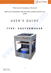
Comments
Pre-fitted
Pre-fitted
Pre-fitted
Pre-fitted
Extruder assembly parts (note that the 2 M4x50 hex head screws in the bottom right of the picture
have been replaced with 2 M4x45 Socket cap screws, and the large spring by an M8 star washer)
M90LC Manual
29 of 70
V0.4-20131016
Method
1. Push the hot end into its socket so the wires come up the front of the wades block and
slightly to the left.
2. Secure it in place with three M3 x 16mm cap screws with M3 star washers and M4 washers
that capture the top of the groove, screwed into the pre-fitted captive nuts. The washers
have to go in from the side before the screws go through them. Be careful to get the screws
vertical to ensure they don't cross thread. It may be necessary to rotate the hot end to allow
the screw heads to clear the zip tie. Ensure all the screws are in place before fully
tightening them, this allows the extruder to be rocked/rotated to get them all in. Make sure it
is aligned as shown before tightening the screws. Be careful not to overly flex the wires
coming out of the hotend as they can break.
3. Place the M4 x 20mm bolts through their holes in the base of the block.
4. Loosely attach the motor with three M3 x 10mm socket cap screws, star and flat washers
M90LC Manual
30 of 70
V0.4-20131016
trapping the M4 bolt below it in place. The 15 pin D type connector should be on the side
closest to the bearings in the wades block (see picture below)
5. Pass all 4 of the wires from the hot end up past the motor underneath the PCB. Attach the
red, hot end heater wires to the terminals marked H. (there is no polarity between these
wires)
6. Attach the green thermistor wires to the terminals marked T. (there is no polarity between
these wires)
7. Push the M8 hobbed bolt through the large gear and make sure it is fully seated. Add the
spacer to the bolt and put the bolt through the bearing block. Ensure that the hobbed
portion of the bolt is directly inline with the filament path. If it is not then the bolt may not be
fully seated. Try pressing it in further or tighten an M8 nut on the other side of the bearing
block to pull the bolt further in.
8. Slide the motor up to engage the gears and rotate them to ensure they don't bind or have
too much backlash. Lock the motor in position by tightening the exposed socket cap screw.
Remove the large gear and hobbed bolt and tighten the remaining screws.
9. Replace the hobbed bolt and gear and check the gears still correctly mesh. Secure with an
M8 nut finger tight. Add the M8 star washer and second nut to lock it in place. Finger tight is
generally enough to stop it shaking loose.
10. Put the springs with a washer on either side on the M4 x 45mm socket cap screws and
thread them through the idler block into the bearing housing and into the trapped nuts.
Tighten them until the screw head with the springs are compressed to 6mm measured
between the washers.
11. Push some filament into the extruder hard against the hobbed bolt whilst turning the large
gear to pull it in. Some force on the filament is needed initially to open the idler but once
you see it open the filament can be fed by just turning the gear.
12. This is the way the extruder is loaded. Normally one would wind it in by hand until it hits
some resistance, then heat the extruder and feed it with the motor. In this case just wind it
up and down and check the gears don't bind. The spring force pushes the bolt a little
further back in the bearings, so you might need to slacken off the motor a bit.
M90LC Manual
31 of 70
V0.4-20131016
12.
Frame Assembly
BOM
Category
Description
MDF
Base
MDF
Portal
MDF
Left buttress
MDF
Right buttress
MDF
Roof
MDF
Bowden extruder mounts - tabbed (optional)
MDF
Bowden extruder mount - no tabs (optional)
Printed
Alu_channel_caps
Sundries
Alu channel 32x13x3, 449 long (handed)
Sub-assembly Z-motors (handed)
Fasteners
M3x16 socket cap screw
Fasteners
M3x20 socket cap screw
Fasteners
M3x25 socket cap screw
Fasteners
M3 form A flat washer
Fasteners
M3 external shake proof (star) washer
Fasteners
M3 nyloc nut
Fasteners
M3 square nut
Qty Comments
1
1
1
1
1
2
1
4
2
2
28
4
2
38
30
4
30
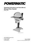
Laser cut frame parts. (Note that the Z motor and top bracket parts are illustrated but it is
easier if these are assembled as sub assemblies first - see the Z Axis Sub-Assembly
section)
Method
All the laser-cut parts are held together with M3x16 socket cap screws fitted with star
and flat washers, and screwed into square nuts fitted to the nut slots in the mating part.
As previously noted, laser-cutting produces parts with a slightly tapered hole so if a
square nut doesn't easily fit into its slot, try it from the other side.
The bolts only need to be tightened enough to compress the star washers partially.
Excessive tightening will damage the captive nut holes in the MDF.
As indicated in the BOM, the Bowden extruder mount is optional as it is only required
when upgrading to dual or multiple extruders. However, fitting it after the machine is
M90LC Manual
32 of 70
V0.4-20131016
built requires a complete strip down and rebuild, so we strongly recommend fitting it
now.
1. Fit the Bowden extruder mount-no tabs between the 2 Bowden extruder
mounts–tabbed, with all the bolt holes aligned, and fix together with 2 x M3x25
socket cap screws, washers and nyloc nuts in any of the holes. These may be
left in place after assembly, or removed if needed as spares. Note that this
“extruder sandwich” should be oriented as shown in the picture with the large
holes slightly closer to the small holes on the right.
2. Lie the right hand buttress support (it has the most holes for mounting the
electronics) on the table so the semi-circular notch is on the right to ensure it is
the right way round. Slot the Bowden sandwich and the rear roof into their slots.
The tabs on the rear roof should also face to the right. Secure these panels in
place.
+
=
3. Fit the left-hand buttress to this assembly and secure in place. The semicircular notch should line up with the right hand side.
M90LC Manual
33 of 70
V0.4-20131016
=>
4. Identify the front and back of the portal – the wider leg is on the right when
looking at the front. Fit the portal to the front of the buttress-assembly and
secure in place. To make securing it easier, slide the nuts into their traps before
attaching the portal.
5. Identify the left and right Z-motor bracket sub-assemblies - the rod-holes are inside
the motor shafts, towards the centre of the machine. Fit the motor-bracket
assemblies to the front of the portal, feeding the cables through the holes provided.
M90LC Manual
34 of 70
V0.4-20131016
6. Use the semi-circular holes in the buttresses to keep the Z Motor cables neat while
completing the remainder of the assembly.
7. Turn the assembly upside-down and fit the base after identifying the correct
way up and fitting square nuts in all the nut traps. Try not to bump the assembly
to avoid knocking nuts out. Align the tabs on one side first, then the other. Do
not apply excessive force but you may need to gently flex the frame so the tabs
line up.
M90LC Manual
35 of 70
V0.4-20131016
8. Fit bolts to the holes which lead to nut traps in the portal and Z-motor-brackets,
but not the left and right hand buttresses. This is to allow for the aluminium
base channels to be added in the next step
9. Line up the aluminium base channels with the buttress holes. They are drilled
to fit left and right with two holes at the back for the buttress M3x20 screws, the
large hole for the head of the portal screw towards the centre of the machine,
and a single hole at the front for an M3x16 socket cap screw. Fix the base
channels through the base into the 4 square nuts in the buttresses with M3x20
socket cap screws, but do not tighten fully. Fit the M3x16 socket cap screws
with washers inserted from the top of the base through the front end channels
and secured with M3 nyloc nuts and washers in the channels, left loose for
now.
10. The bolt-holes in the channels are large enough to allow the channels to slide
backwards and forwards a little. Push the channels all the way to the back of
the machine to align with the rear edge of the frame base, then tighten all the
bolts. The Alu_Channel_Caps can be fitted now but they are best left to the end
as the frame will be moved around during the remainder of the assembly
process.
M90LC Manual
36 of 70
V0.4-20131016
11. The frame assembly is complete, now move onto the Y Axis Assembly.
M90LC Manual
37 of 70
V0.4-20131016
13.
Y-Axis Assembly
BOM
Category
Electrical
Electrical
Electrical
Electrical
Fasteners
Fasteners
Fasteners
Fasteners
Fasteners
Fasteners
Fasteners
Fasteners
Fasteners
Fasteners
Fasteners
Fasteners
Fasteners
Fasteners
Fasteners
Fasteners
Mechanical
Mechanical
Mechanical
Printed
Printed
Printed
Printed
Printed
Sub-assembly
Sub-assembly
Sub-assembly
Sub-assembly
Sub-assembly
Sundries
Sundries
Sundries
M90LC Manual
Description
Qty Comments
Heatbed wiring loom
1
Micro switch end stops
1
PCB heatbed Mk2a assembly
1
Y-endstop cable - 950long
M2.5 flat washer
2
M3 External Shake proof (star) Washer
3
M3 Form A Flat Washer
8
M3 Form A Flat Washer
4
M3 Full Nut
3
M3 Nyloc Nut
2
M3 Nyloc Nut
4
M3x10 Socket Cap Screw
3
M3x16 Socket Cap Screw
3
M3x16 Socket Cap Screw
4
M3x20 Hex PCB spacer F/F chromed brass
3
M3x20 Socket Cap Screw
2
M4 Form A Flat Washer
10
M4 Nyloc Nut
10
M4x20 Socket Cap Screw
10
No 2 x 1/2 Pozi Pan S/T screw
2
Round rail hardened and ground 274mm long (Y) 1
Round rail hardened and ground 417mm long (Y) 1
T2.5 timing belt Y=668mm
1
ribbon_clamp_26_33
1
ribbon_clamp_26_33N
1
ribbon_clamp_26_44N
1
y_bar_clamp
3
y_bar_clamp_switch
1
Print-bed
1
Y-carriage
1
Y-heatshield
1
Y-idler
1
Y-motor
1
Bulldog clip 19mm
1
Glass sheet 214 x 202 x 3, 2x10x10 chamfer
1
Polypropylene strip 270 x 33 x 0.5
1
38 of 70
V0.4-20131016
Sub Assemblies
Method
Y axis assembly (note the heatbed and heat shield are not shown)
1. Insert the M3x16mm socket cap screws in each of the Y bar clamps so they engage with
the pre-fitted captive nyloc M3 nuts.
2. Turn the machine onto its side. Loosely fit the two left hand Y bar clamps to the base with
the M4 x20mm socket cap screws, oriented so the slits in the clamps are towards the
inside of the machine. Carefully insert the long Y-rod to line up the brackets, using a gentle
twisting motion.. Tighten the fixing bolts through the machine base but do not tighten the
M3 clamping bolts, then remove the rod.
M90LC Manual
39 of 70
V0.4-20131016
3. Plug the spade connectors of the green-and-black Y-endstop cable onto the Y-endstop
micro switch, bending the bottom connector downwards at an angle. Screw it to the
y_bar_clamp_switch with No2 pozi pan self-tapping screws and M2.5 washers with the
button towards the top and facing the back of the machine.
4. Fit the right hand Y bar clamps to the base but leave the screws loose enough that the
clamps can move during the alignment in step 13.
M90LC Manual
40 of 70
V0.4-20131016
5. Plug in the Y motor cable, thread the Y motor wires through the hole in the base and then
screw the Y motor bracket securely in place.
6. Thread the Y limit switch and motor cables through the cable ties, along the underside of
the base through a second cable tie, up through the hole in the base and then through the
adjacent hole in the right buttress as shown below.
7. Fit M3 x 16 socket cap screws from below to the 2 back corner holes and central front hole
of the Y carriage, using star washers and flat washers underneath and flat washers and full
nuts above. Tighten firmly but do not over tighten as the MDF is slightly compressible. Add
an extra washer on top of the nut on the 2 rear bolts and screw the pillars down firmly at
the back.
8. Screw the front pillar down to the same height by using a washer as a temporary shim
(don’t slide it onto the bolt but rest it on the nut so it is pinched by the hex pillar). The front
pillar is used to level the bed relative to the nozzle in the Y-direction (front-to-back), this
washer, acting as a shim, sets it close to correct as a start point. Any difference in level in
the X-direction is corrected on the Z-axis lead screws, not on the heat bed.
9. Clamp the Y belt (the shorter of the two) in the front belt anchor with the teeth facing away
from the carriage. The end of the belt should project enough to have four complete teeth
showing.
M90LC Manual
41 of 70
V0.4-20131016
10. Put a half twist in the belt and the thread it through the Y idler assembly with the smooth
side against the bearings and then clamp it in the rear clamp with the teeth facing the
carriage. Again leave four complete teeth projecting from the anchor.
11. Slide the left Y bar through the bar clamps and the carriage bearings, using a gentle
twisting motion to avoid knocking balls out of the bearings. Tighten the clamps to grip the
bar lightly but do not over-tighten them
12. Repeat the process for the right bar, then slide the carriage up and down to align the right
hand bearing and bar clamps. Tighten the bearing first and then move the carriage to each
end and tighten the clamps.
13. Put the belt over the motor pulley and fasten the idler assembly to the base with enough
tension on the belt to play a low note when plucked. Ensure the belt runs in the middle of
the idler without touching the washers each side by adjusting the angle of the idler.
Similarly the position of the pulley on the motor shaft may need to be adjusted slightly.
14. Lay the heat bed cable loom (ribbon-cable) on the y carriage as shown, using M3 x 20mm
screws and washers, clamp it together with the polypropylene strip (which goes closest to
the clamp) to the y carriage with the ribbon_clamp_26_33 and ribbon_clamp_26_33N.
M90LC Manual
42 of 70
V0.4-20131016
15. Lay the heat shield on the Y carriage with the notch at the back between the underside of
the bed and the cable. The heat shield can be taped into place as shown with short pieces
of the supplied aluminium tape.
16. Plug the two 6x2-way IDC connectors on the bed end of the bed ribbon cable onto the 6x2pin headers soldered to the front edge of the heat bed and plug the thermistor connector
onto the white 2-pin header stuck to the back of the heat bed. Screw the bed to the top of
the pillars with the M3 x 10 socket cap screws (no washers).
M90LC Manual
43 of 70
V0.4-20131016
17. The ribbon cable and polypropylene strip route towards the front of the printer under the y
axis before doubling back. Clamp the bed's ribbon cable and polypropylene strip to the
base with the ribbon_clamp_26_44N. The wires turn right and go through the cable ties
and under the holes in the right hand stay. The heater wires go through the rear tie and the
larger hole
M90LC Manual
44 of 70
V0.4-20131016
14.
Z Axis Assembly
BOM
Category
Description
Round rail hardened and ground 344mm long
Mechanical
(Z)
Sub-assembly Z-top-bracket assemblies
Sub-assembly Z-endstop assembly
Sub-assembly Y-idler
Sub-assembly Y-motor
Fasteners
M3x16 socket cap screw
Fasteners
M3 form A flat washer
Fasteners
M3 external shake proof (star) washer
Fasteners
M3 square nut
Qty Comments
2
1
1
1
1
4
4
4
4
(Note that the threaded rod and couplings are used in the next section)
(Note that the cable loom is gathered together for the photograph only)
Method
The X motor and idler sub-assemblies form the interface between the X and Z axis.
They are part of the X axis but are assembled with the Z axis.
1. Fit the Z top endstop and feed the cable through the hole. It is routed alongside the
z-motor wires and zip tied into place. The endstop is best fitted in the centre of the
slot range to start with, it will be adjusted later.
2. Fit the Z-top-brackets to the front of the portal with M3 x16mm socket cap screws,
washers and square nuts, with the 8mm holes for the Z-rods facing inwards towards
the centre of the machine. Tighten the bolts to keep the brackets steady for the next
step
M90LC Manual
45 of 70
V0.4-20131016
3. Gently slide the smooth rods through the top brackets and partway down towards
the Z-motor brackets. They are a tight fit so work slowly, supporting the brackets. If
they will not move then twist gently as you push but do not be tempted to hammer
them or use excessive force.
4. Once the rods are partway down, insert them through the X-ends with the idler on
the left and the motor box on the right. Twist the rods gently to avoid knocking out
the balls out of the linear bearings, then push them all the way down into the
matching holes in the Z-motor brackets.
5. Slacken off the Z-top-brackets fixing screws just enough to allow them to move
slightly when the X-axis is fitted.
M90LC Manual
46 of 70
V0.4-20131016
15.
X-Axis assembly
BOM
Category
Description
Mechanical Round rail hardened and ground 381mm long (X)
Mechanical M5 threaded rod lead screws 305 long
Mechanical Beam couplings 5mm/5mm
Printed
ribbon_clamp_20_44N
Printed
ribbon_clamp_20_44
Sub-assembly X-carriage
Sub-assembly X-carriage-fan
Sub-assembly Extruder
Fasteners
M4 nyloc
Fasteners
M4 Flat washer
Fasteners
M4x20 socket cap screw
Fasteners
M4 Wing nut
Qty
2
2
2
1
1
1
1
1
2
2
2
2
Comments
Pre fitted
Note the shorter smooth rods shown in the picture above have already been fitted as part of the
Z axis assembly
Method
1. Put the X ends at the bottom of the Z axis. Make sure the X bars are free of
grease to help the clamps to grip. Remove the idler's axle bolt.
M90LC Manual
47 of 70
V0.4-20131016
2. Slide the X bars through the idler bracket, the X carriage and into the motor bracket
as far as they will go. Take care when passing the rods through the X carriage
bearings, twisting them to ensure no ball bearings are knocked out. You may find it
helpful to support the carriage, for example by using the empty power supply box.
3. Tighten the X bar clamps while the axis is at the bottom. Tighten the 4 cap screws of
each bar clamp evenly in a criss-cross pattern. Don't over tighten them, i.e. tighten
just enough until you feel the clamp grips the bar solidly.
4. Put the belt round the motor pulley and then re-attach the idler axle with the belt
around the idler.
5. Tension the belt enough to play a low note when plucked.
6. Run the carriage side to side a few times and check that the belt does not rub on
M90LC Manual
48 of 70
V0.4-20131016
the edge of the pulley. If it does, slightly adjust the position of the motor pulley so
that it runs true.
7. Move the axis to the top and then tighten the Z-top-brackets. The axis is now
aligned top and bottom. Move the X-axis up and down the Z rods a few times to
confirm it runs smoothly. If it does not then use the slight play in the Z-top brackets
when the screws are slackened to allow it to run smoothly
8. Pass the connectors at the end of the X Motor and Extruder loom through the slot
on the right hand side of the portal and fix the loom in place with the
ribbon_clamp_20_44N on the front and the ribbon_clamp_20_44 .on the back. Form
the loop using the polypropylene strip, this is best done with the carriage half way
up the Z axis. .
9. Fit the beam couplings to the Z-motors with the motor shaft projecting no futher than
half way through the coupling, and tighten the grub screws. It may be helpful to use
a piece of cardboard or similar as a spacer to ensure the couplings are the same
distance from the top of the motor. Once again supporting the X axis out of the way
using the power supply box makes this process easier. Tighten the clamp bolts to
take up the slack. There is no need to apply excessive force to tighten these to the
motor shaft.
10. Lower the x axis to heat bed. Insert the M5 lead screws through the holes in the top
brackets, drop them down to the X-ends and screw them through the pre-fitted M5
nuts.
11. Continue to thread the lead screws down into the top of the beam couplings, once
they are all the way to the top of the motor sharft, back them up 2 full turns to
ensure there is a gap to allow the couplings to flex. Tighten the beam coupling
clamp bolts first, as tight as possible, then tightening the grub screws as well.
M90LC Manual
49 of 70
V0.4-20131016
12. Slot the extruder into place with the gears closest to the portal and secure it with the
M4 wing nuts, ensure the hotend cable does get pinched by the gap between the Xcarriage and the extruder body. If the right hand wing nut stops in a position where it
sticks out beyond the carriage try the hex head in a different one of the six possible
positions.
13. Mate the D type connectors and screw the captive M3 screws in the shell into the
captive M3 nuts in the d_motor_bracket. Do not over tighten them.
M90LC Manual
50 of 70
V0.4-20131016
16.
Electronics Assembly
BOM
Category
Electrical
Electrical
Electrical
Electrical
Electrical
Electrical
Electrical
Electrical
Electrical
Printed
Printed
Fasteners
Fasteners
Fasteners
Fasteners
Fasteners
Fasteners
Fasteners
Fasteners
Fasteners
Fasteners
M90LC Manual
Description
RAMPS1.4
Arduino Mega 2560 compatible board
Blue Stepsticks with loose heatsinks
Panelolu2 LCD controller with RAMPS1.4 adaptor
PSU ALPINE 600 assembly
IEC PC PSU mains lead with moulded-on plug
Micro SD card
Micro SD to USB adapter
USB A to B lead x 1.5m long
ATX_PSU_bracket short
ATX_PSU_bracket long
M3x10 socket cap screw
M3x16 socket cap screw
M3 form A flat washer
M3 external shake proof (star) washer
M3x20 Hex PCB spacer F/F chromed brass
M4x20 socket cap screw
M4 form A flat washer
M4 external shake proof (star) washer
M4 nyloc nut
6-32 x 1/2 pan screw
51 of 70
Qty Comments
1
1
5
1
1
1
1
1
1
1
1
7
3
7
7
3
4
6
2
4 Pre-fitted
2
V0.4-20131016
Method
1. Turn the frame onto its left side so the electronics bay is on top and facing towards
you. Be careful that the x or y carriage don’t crash from end to end while turning it
around.
2. The M4 nyloc nuts are pre-fitted in the nut traps of the two brackets. Loosely screw
the brackets to the frame with M4 x 20mm socket cap screws and flat washers. The
long bracket runs vertically close to the back with the tall lug at the base. The small
bracket joins between the base and portal so the smooth flat side is on top as you
see it. The brackets are designed to provide a slot for the power supply to fit into.
3. Run the wires from the right Z motor, the Y motor, the Y endstop and the bed up the
corner between the portal and the right buttress before fitting the PSU between the
brackets.
M90LC Manual
52 of 70
V0.4-20131016
4. The PSU is aligned so the fan faces up and the switch is to the back. Check no
wires are trapped underneath the PSU then secure it into place with two 6-32 x 1/2
pan screws, M4 star washers and M4 flat washers. Tighten the brackets holding the
PSU to the frame.
5. The resistor lugs are tapped M3. Fix the resistors to the frame using four M3 x
10mm socket cap screw screws, star washers and flat washers (The resistor
locations have changed slightly since the picture was taken). Insert the screw from
the other side of the frame using the resistor lug as the nut.
IMPORTANT NOTE. The Arduino + RAMPS + Stepsticks combination forming the
electronic controller can be damaged if the wiring is incorrect, or by failure to observe
antistatic precautions when handling. The controller is supplied loaded with Marlin firmware
configured for the Mendel90 with Panelolu LCD panel, and has had a full functional test
with the actual wiring looms and cables, motors, limit switches, hotend, heatbed and fan
supplied in the kit.
6. Fit the hex pillars to the buttress with three M3x16 socket cap screws, star and flat
washers from behind (underneath with the machine on its' left side). Use the picture to
identify the correct holes.
7. Fit the Arduino vertically so the USB socket points towards the PSU to the tops of the
hex pillars with M3x10 socket cap screws without washers securely but not over tight.
M90LC Manual
53 of 70
V0.4-20131016
8. Fit the RAMPS to the Arduino, making sure all the pins line up.
9. Connect up all the wiring, referring to the RAMPS wiring schematic if uncertain. Careful
routing of some of the cables under the board will make the finished job look much
tidier and the cables can be grouped together with cable ties.
Green power plug from PSU into green 4-way RAMPS socket
Heatbed power cables into RAMPS D8
Extruder power cables into RAMPS D10
Fan single wire into GND terminal of RAMPS D9
Ribbon cable wires (all labelled) onto X-motor, E-motor, X-endstop (red to
outside), and E-thermistor.
Y- and Z-motors and end stops and heatbed thermistor
Ensure end stops are connected between S and GND(coloured wires towards
the outside)
10. Fit Panelolu 2 ribbon cable and Panelolu2
11. Attach the USB cable, which will be used along with your PC during calibration of the
printer.
This concludes the assembly process prior to commissioning and calibrating your printer. The Xcarriage fan assembly is best fitted after calibration. If you are fitting the optional acrylic cabinet
then this is also best done after calibration, and is covered in a separate section later in this
manual.
M90LC Manual
54 of 70
V0.4-20131016
17.
Firmware and Software
The micro SD card with the kit comes preloaded with software to operate the machine on Windows
(Linux versions of all the tools are available online). Please copy the files from the SD card to
somewhere safe on a computer.
After this has been copied to your PC the card can be wiped and used with the Panelolu2 to run
the machine. Running G code from the card gives more consistent results than sending it over
USB. A USB SD card reader is included in the kit to allow G-codes to be loaded to the card from
your PC. Once the machine is fully calibrated you should be able to control prints entirely with the
Panelolu2, without having to attach the PC again. There is a command tree in the Marlin directory
(LCD Menu Tree.pdf) which shows the controls available.
The following programs are included: Marlin Firmware
This is the source code for the firmware that is pre-loaded on the Arduino and is located in
the directory Marlin_T3P3_M90LC_v0_7. It is our fork of Marlin with Panelolu2 support and
is also available on GitHub at https://github.com/T3P3/Marlin. The pre-installed version is
sufficient to test the machine but calibration will be required, which involves tweaking the Z
axis height and the hobbed bolt diameter.
Arduino IDE
This is used to compile and load the firmware and is located in the arduino-0023 directory
Once copied to your PC it can be run simply by clicking on arduino.exe, as no installation is
needed. It can also be downloaded from http://arduino.cc/en/Main/OldSoftwareReleases.
Although not the latest version of Arduino, it has been thoroughly tested for Marlin uploads
and is very reliable.
When started it opens an empty sketch. Use the File/Open menu to navigate to
Marlin_T3P3_M90LC_v0_7\Marlin_T3P3_M90LC_v0_7.pde and click on it. Marlin opens
in a new page. Click on the configuration.h tab and:
1. Find Line 306 “#define Z_MAX_POS 210”. This will need to be changed to the
actual Z-height in mm as determined by calibration (described in the next section of
this manual).
2. Find Line 328 “#define DEFAULT_AXIS_STEPS_PER_UNIT {80,80,3200/0.8,520}
“. The last number 520 is the extruder steps in mm. This will need to be confirmed
by calibration.
When you are directed below to update the firmware do the following: •
Use the Tools / Board menu option to set the board to “Arduino Mega 2560”.
•
Use the Tools / Serial Port option to select the correct USB port.
•
Press the play button.
•
Wait for”Done uploading” to appear.
•
Save your changes with the save button.
Pronterface
This is a host application used to control the printer downloaded from
http://koti.kapsi.fi/~kliment/printrun/ and is located in the directory Printrun-Win-Slic3r12July2013.
Again it needs no installation. Simply copy the folder to hard disk and run Printrun-WinM90LC Manual
55 of 70
V0.4-20131016
Slic3r-12July2013\pronterface.exe.
Slic3r
This is the software used to produce G-code print files from the STL files produced by CAD
programs. Download the latest version of Slic3r from http://slic3r.org/. The current version
at the time of writing is also stored on the uSD card supplied with your kit.
Help on using Slic3r is available on the Slic3r website at http://manual.slic3r.org/. We
supply the basic settings for the M90LC as a configuration file
(M90LC_default_PLA_config.ini) on the uSD card.
M90LC Manual
56 of 70
V0.4-20131016
18.
Testing and Commissioning
Power up
Plug in the mains and switch on the PSU. The PSU fan should run, and the Panelolu2
display should come to life. Connect the USB lead to a PC and a USB connection should
appear. The Arduino board comes with Marlin installed and configured for 250kB.
Open Pronterface, set the baud rate and serial port and press “Connect”. After a few
seconds the following should be displayed.
Connecting...
start
Printer is now online.
Marlin 1.0.0
echo: Last Updated: Oct 8 2013 08:22:09 | Author: (T3P3, M90LC v0.7)
20130925
Compiled: Oct 8 2013
echo: Free Memory: 4340 PlannerBufferBytes: 1232
echo:Hardcoded Default Settings Loaded
echo:Steps per unit:
echo: M92 X80.00 Y80.00 Z4000.00 E520.00
echo:Maximum feedrates (mm/s):
echo: M203 X300.00 Y300.00 Z3.20 E45.00
echo:Maximum Acceleration (mm/s2):
echo: M201 X1000 Y1000 Z10 E45
echo:Acceleration: S=acceleration, T=retract acceleration
echo: M204 S1000.00 T3000.00
echo:Advanced variables: S=Min feedrate (mm/s), T=Min travel feedrate
(mm/s), B=minimum segment time (ms), X=maximum XY jerk (mm/s), Z=maximum
Z jerk (mm/s), E=maximum E jerk (mm/s)
echo: M205 S0.00 T0.00 B20000 X20.00 Z0.40 E5.00
echo:Home offset (mm):
echo: M206 X0.00 Y0.00 Z0.00
echo:PID settings:
echo:
M301 P38.60 I4.55 D81.79
echo:SD init fail
Reading through this list you will see that it tells you what most of your Marlin
configuration.h settings are. This can be useful when configuring a new version of Marlin
before upload, if you forgot to save the last Marlin upload.
Limit switches
Check that the limit switches are working by typing M119 in the test box at the bottom right
corner of the Pronterface window. When no switches are triggered they should all read low:
SENDING:M119
Reporting endstop status
x_min: open
x_max: open
y_min: open
y_max: open
z_min: open
z_max: open
Check that manually triggering each switch causes the corresponding input to change from
open to TRIGGEREDH while the switch is held down. Also check that each axis is able to
hit its limit switch. For X the extruder wing nut can get in the way. If this is the case simply
rotate the hex head bolt in its socket. The Z axis must be reasonably level side to side so
that the right hand side doesn't hit the top of the axis before the left side hits the limit
M90LC Manual
57 of 70
V0.4-20131016
switch. The micro-switch must be mounted in the correct orientation for the lever to strike
its intended target (X with the lever hinge towards the top , Y towards the top, Z towards the
back).
Motors
Put some lubricant on the X,Y and Z smooth rods and the Z lead screws and lithium grease
on the extruder gears. ABS gears will run continuously for months with grease but wear out
more quickly when run dry.
Move all of the axes manually to somewhere near the centre. Then check that all the axes
move in the right direction by using the jog buttons in Pronterface. Click on the “10” ring in
the +X quadrant and check that the carriage moves 10mm towards the right, towards the
limit switch.. Since the limit switches have been verified to be working and the motor is
running in the right direction it is now safe to home by pressing the X home button (house
icon with an X).
Repeat the procedure for the Y axis. +Y moves the bed towards the switch.
Check the extruder feeds forwards when the “Extrude” is pressed and backwards when the
“Reverse” button is pressed. Marlin will prevent you from doing 'cold extrusion'; you can
override this with command M302, then try the extrude again. Make sure you don't have
any filament loaded during this test.
Heaters
Tick the “Monitor Printer” to show the temperature graph. The figures under the “Check
Temp” button should show the hot end (T) and the bed (B) to be around room temperature.
Set the “Heater:” target temperature to 220˚C and press the “Set” button. The temperature
of the hot end should rise and settle at 220˚C. If you have a thermocouple probe you can
insert it inside the hot end and verify the temperature at this stage (before the barrel is filled
with plastic). To do this you will need to remove the idler and stiffen the thermocouple wire
by sleeving it with about 150mm of PTFE tubing with an outside diameter less than 3mm.
Pressing the blue “Off” button should cause the temperature to slowly fall back to room
temperature again.
Repeat the same procedure with the bed heater by setting it to 60˚C.
M90LC Manual
58 of 70
V0.4-20131016
19.
Calibration
Firmware setup
The standard supplied firmware is already set up for the M90LC. The following lines within
configuration.h are different from the default version of Marlin.
#define STRING_CONFIG_H_AUTHOR "(T3P3, M90LC)" // Who made the changes.
#define MOTHERBOARD 33
#define TEMP_SENSOR_0 5
#define TEMP_SENSOR_1 0
#define TEMP_SENSOR_BED 12
const bool X_ENDSTOPS_INVERTING = false;
const bool Y_ENDSTOPS_INVERTING = false;
const bool Z_ENDSTOPS_INVERTING = false;
#define DISABLE_Z true
#define
#define
#define
#define
INVERT_X_DIR false
INVERT_Y_DIR false
INVERT_Z_DIR false
INVERT_E0_DIR false
#define X_HOME_DIR 1
#define Y_HOME_DIR 1
#define Z_HOME_DIR 1
// Travel limits after homing
#define
#define
#define
#define
#define
#define
X_MAX_POS
X_MIN_POS
Y_MAX_POS
Y_MIN_POS
Z_MAX_POS
Z_MIN_POS
200
0
200
0
210
0
And we will set the Z axis height accurately in a later step
//leave commented out!
//#define MANUAL_HOME_POSITIONS
#define
#define
#define
#define
#define
#define
HOMING_FEEDRATE {30*60, 30*60, 3.3*60, 0}
DEFAULT_AXIS_STEPS_PER_UNIT
{80,80,3200/0.8,520}
DEFAULT_MAX_FEEDRATE
{300, 300, 3.3, 45}
DEFAULT_MAX_ACCELERATION
{1000, 1000, 5, 45}
DEFAULT_ACCELERATION
1000
DEFAULT_RETRACT_ACCELERATION 3000
// (mm/sec)
#define EEPROM_SETTINGS
#define EEPROM_CHITCHAT
//if you have one plugged in
#define PANELOLU2
Nozzle-bed alignment 1 – X axis levelling
1.
If you have fitted the extruder fan, then remove it for this stage of the calibration. Fit
the heatbed glass if not already done
2.
Connect to the printer using Pronterface
3.
Centre the X carriage on the x axis then home the Z axis in Pronterface by clicking
M90LC Manual
59 of 70
V0.4-20131016
on the Button with Z and a picture of a house.
4.
Click “Disable Motors” in Pronterface and then manually move the X and Y axis so
that the nozzle is in the left most (minimum) position on X ( X=~0) and almost to
the maximum on Y, just clearing the bull dog clips (remember Y axis is described
with reference to the nozzle, not the bed so with the nozzle at the top of Y, the bed
is all the way forward).
5.
Using the Z +/- buttons in Pronterface move the Z axis so that the nozzle is nearly
touching the bed. Use a sheet of paper as a feeler gauge to check the nozzle
height. While moving a sheet of paper under the nozzle, lower the Z axis until the
paper just begins to drag against the nozzle. Be careful not to push down on the
bed when using the paper as a feeler gauge.
6.
Use the Z+1 button to lift the nozzle slightly above the paper and bed and then
move the X carriage all the way to the right most (maximum) position (X=~200).
Once in this position use the Z-1 button to drop the extruder back to the position it
was at on the other side.
7.
Click “Disable Motors” in Pronterface then, while holding the left Z coupling still with
one hand adjust the right side of the X axis up or down using the right coupling until
a piece of paper just drags under the nozzle. This is the first iteration done, however
because the Z axis rods are further out then the edge of the bed we need to go
through this process a number of times until no further adjustment is needed.
8.
At this point use the Z+1 button in Pronterface to move the X axis up by 1mm, then
move the x axis all the way across to the other side and repeat steps 5 to 7 until
there is no difference in height between either side of the X axis.
9.
The next step is to adjust the bed to be level on the Y axis.
Nozzle-bed alignment 2 – Y axis levelling
1.
Ensure the X axis levelling step is completed then move the X-Axis so the nozzle is
in the centre on X and almost all the way to the maximum on Y (i.e. the bed is all the
way forward)
2.
Move the nozzle down until it just drags on the paper used as a feeler gauge, as in
the X axis levelling. Once again be careful not to push down on the bed when using
the paper as a feeler gauge.
3.
Use Z +1 to lift the nozzle from the bed slightly, then move the Y axis so the bed is
all the way back. Use Z-1 to return the nozzle to the height it was at the other end
of the Y axis. The nozzle should be just on the paper feeler gauge at the front.
4.
In adjustment is required (ie the nozzle does not touch the paper or the paper is
pushed down onto the bed, loosen the top screw on the bed mount hex pillar at the
front slightly and then turn the hex pillar to raise or lower the bed slightly until the
paper just drags on the nozzle. Tighten the top screw and confirm the paper still just
touches the nozzle.
5.
Use Z+1 to lift the nozzle slightly, return the bed all the way to the back.
6.
Repeat above steps until there is no adjustment required between the front and
back of the Y axis.
Setting the Z axis dimension
1.
If not already connected, connect to the printer using Pronterface and set the bed
and nozzle temperature to the desired printing temperature (135 bed, 250 extruder
for ABS, 80 bed, 200 extruder for PLA). Z-height calibration should be done with
M90LC Manual
60 of 70
V0.4-20131016
everything at the printing temperature. Care should be taken not to touch the hot
surfaces during this process.
2.
Centre the X carriage in the X axis, then home the Z axis. Once the Z axis is at the
top check for fouling at the Z motor ends as at Z-Max position. If there is still
clearance and you wish to have maximum Z height then the Z endstop can be
raised in the slot slightly, before being re-tightened. Similarly if there is fouling then
the Z endstop can be lowered in its slot slightly to ensure the extruder clears the Z
top Brackets with the X carriage all the way to the right. Re center the carriage on X
and home Z between any endstop adjustments.
3.
Type M114 to show the current X, Y and Z points, which should be X 200, Y 200, Z
210 if you are using our default version of marlin distributed with the kit.. Record the
Z figure as Z_original.
4.
Move the X carriage to the centre of the X axis and the Y carriage to the centre of
the Y axis so the extruder is over the centre of the bed.
5.
Type G1 Z20 to move the extruder to just above the bed, then use the Z- buttons in
Pronterface to lower the extruder until just catches on a piece of paper, used as a
feeler.
6.
Type M114 again. This will show the current Z position. Record this as Z_error
7.
7.
Now you know Z_original was too big by Z_error, so subtract Z_error from
Z_original and you have the correct Z-height within a sheet of paper. Add 0.1mm to
that, which is about the thickness of a sheet of paper. So Z_original - Z_error + 0.1 =
Z_correct
8.
Disconnect from Pronterface, open Arduino, open Marlin, set the value
Z_MAX_POS to Z_correct in configuration.h and upload.
9.
Once upload is finished heat up bed and nozzle as they will have cooled, home the
M90LC Manual
61 of 70
V0.4-20131016
printer and type M114 - this should now be the correct value for z_correct.
10.
Centre the nozzle in X and Y, type G1 Z5 or move the nozzle down to just above the
bed, then do the paper trick again and the paper should bind when M114 reports Z=
~0.1mm.
Extruder E-steps calibration.
1.
Move the nozzle so it is clear of the bed (half way up the Z axis) and heat to 200C
for PLA or 250 for ABS
2.
“Disable Motors” then insert filament by hand, turning the large gear to feed it
through until some is extruding.
3.
Using a set of callipers or an accurate ruler measure up 30mm from where the
filament enters the top of the extruder block. Mark with a felt tip pen.
4.
Using Pronterface extrude 20mm then switch to 1mm extrudes, counting the total
distance commanded until the felt tip mark lines up with the top of the extruder
block. Measure again and repeat, ensuring that the same result occurs. (If they are
different try once more, if still getting varying amounts then there is a problem with
the filament feed. Check the spring tightness). In this example, assume distance
commanded to feed a measured 30 mm is actually 32 mm, substitute you own
measurements.
5.
Calculate the new E steps value in the following way:
(distance commanded/distance measured) * current E_Steps = new E_steps
The original E_steps set in firmware was 520 so the first time this is done current E_Steps
is 520.
e.g. (32/30) * 520 = 554.6 ~ 555 mm
Enter the new E_steps in Pronterface using “M92 E555”. At this point extrude 10mm to get
round a bug in the firmware that messes with the first extruded amount following the
M92 command.
6.
Repeat steps 2. to 6. until there is <1mm difference between what is commanded
and measured.
7.
Use M500 to store the settings then M503 to check the current settings.
8.
Repeat steps 2 to 6 with an extrusion length of 60mm, remembering to change the
distance measured in the formula to 60. Once again stop once the difference is
<1mm.
Repeat step 8 with 100mm, at the end of this the error is <1%
Calibration objects.
1.
Treat the bed according to the type of filament (eg hairspray for PLA, ABS juice for
ABS).
2.
Unzip the appropriate version of Slic3r (32 or 64-bit), run it and Import the
M90LC_default_PLA_config.ini configuration file.
3.
Measure your filament diameter with the callipers: ensure the filament is measured
directly across, straightened out of the natural curve, and make multiple
measurements and take the average. Our standard filament 2.85-2.9 mm.
4.
Add the 30mm hollow box and export G-code then print.
M90LC Manual
62 of 70
V0.4-20131016
5.
You have successfully printed your first object, a simple single walled cube. The
advanced calibration section in the User Manual will contain tips for further
calibration however at this point the printer is calibrated. The final task is to fit the
fan and the acrylic enclosure if that option has been purchased.
Fitting the fan
1.
Slide the fan assembly's bracket onto the M3 screws on the front of the carriage and
tighten them. The fan should sit level. If it droops downwards it may foul the clips
holding the glass. In which case add a shim between the bracket and the carriage
above the screws to make it level.
2.
Plug the fan into the 3 pin connector on the distribution PCB. The red and black
wires should line up with the F+ and F- labels.
To test type M106 in Pronterface to turn the fan on and M107 to turn it off. The Slic3r
profiles can be adjusted to control when the fan come on during printing.
M90LC Manual
63 of 70
V0.4-20131016
20.
Acrylic Enclosure Assembly
The acrylic enclosure is fitted using the same fastening method at the frame. In the same way as
the frame, the laser cutting process means that the holes are slightly wider on one side so if a
square nut does not fit easily from one side, try the other side. Take care to align the acrylic panels
with the frame as the screws are tightened.
When moving the printer about during this process take care to control the X and Y carriage so
that they don’t crash from end to end.
Side panels
These are fitted first with the slots for the door hinges to the front and the “t” shaped cutouts
to the top.
M90LC Manual
64 of 70
V0.4-20131016
Back panel
This is fitted next, the easiest way is to put the printer on the front, resting on the side
panels and then put the square nuts in the frame before screwing on the back panel. Take
care not to knock the square nuts out.
Back panel fitted with the printer back on its base
Top Panel
This fits on with the laser cut slot towards the left side.
M90LC Manual
65 of 70
V0.4-20131016
Doors
The door hinges are adjustable to allow for exact alignment up and down and the frame
and the hinges are slotted to allow for left and right and forward and backwards adjustment.
Apply the back rubber pads to a top and bottom corner of each door. These pads are to
prevent damage to the acrylic and increase the hinge grip.
The hinges are right and left handed, identify which way round they go then attached them
to the doors using the black plastic screw. Tighten the screw enough that they do not fall all
but do not over tighten, these will be adjusted further in a later step.
M90LC Manual
66 of 70
V0.4-20131016
Fit the hinges with the countersunk screws in the hinge groves and the washers and nyloc
nuts on the other side of the top acrylic panel at the frame base.
Once fitted, close the doors, it is likely they will not line up perfectly first time. Use the
adjustability in the hinges to set first one door then the other square with the top acrylic
panel and then adjust left and right until they close with no gap.
M90LC Manual
67 of 70
V0.4-20131016
21.
Operating Instructions
These operating instructions are enough to get started with using the printer. More detailed
instructions will be contained in the upcoming user manual.
Heated Bed
The purpose of the heated bed is twofold: to reduce warping and to make the first layer
stick. In general molten plastics don't stick well to cold smooth surfaces but they will stick to
some hot surfaces.
As each layer is laid down it cools and shrinks a little due to thermal contraction. The
second layer welds on to the first layer and then tries to contract, putting stress on it. The
next layer does the same and eventually the cumulative stress becomes enough to
overcome the adhesion of the first layer to the bed and the corners start to lift and curl up.
By keeping the object warm the amount of contraction is reduced until the bed is switched
off at the end and then all the layers cool to room temperature together.
The ideal temperature for the surface of the bed is just below the glass transition
temperature of the plastic (Tg). This is the temperature at which the plastic transitions from
a rubbery state to a rigid or glass like state. As the plastic cools from the molten state all the
way down to Tg it isn't solid enough to stress the layer below. Stopping it cooling just below
Tg means it doesn't contract much at all past the point where it is solid enough to stress the
layer below and it is rigid enough to support the layer above.
The temperature of the bed is measured underneath, so the temperature at the surface of
the glass is around 15˚C lower. PLA has a glass transition around 55˚C, so 70˚C is a good
temperature to set the bed to. It can be set to a higher temperature for the first layer to
increase adhesion, but after that it must be below Tg.
At the end of the build PLA objects will come loose when the temperature drops below
about 35˚C due to the different contraction rate of the plastic and the glass.
ABS is more difficult because it has a higher glass transition and higher thermal expansion
coefficient. In addition it doesn't stick well to bare glass. A bed set temperature of 120˚C130˚C is needed and the bed struggles to reach that temperature without insulation under
it. Covering the top surface with a sheet of corrugated cardboard makes it warm up much
faster.
To make ABS stick to the glass it will need some form of coating. A thin layer of a dilute
solution and ABS in acetone works. PET or Kapton tape gives more adhesion but the
disadvantage is the objects don't come loose when the bed cools and need to be prised off.
Changing filament
Do not to let the extruder run out of filament. If it does it will lose grip as soon as it gets
past the hobbed bolt, making it difficult to remove as you cannot simply rewind it. You would
have to remove the idler screws and grab the end with snipe nose pliers and pull it out
while hot.
Removal
To change to a new reel of filament heat the extruder to normal operating temperature then
rewind 100mm at ~120mm/min. When the bit that has been molten gets to the hobbed bolt
there will come a point where it is too thin or soft to be gripped. At this point pull it with
enough hand tension to stop it from slipping and keep up the tension until it is all the way
out. Do not stop rewinding it when it is part way out. This can cause soft filament to
M90LC Manual
68 of 70
V0.4-20131016
expand into the entrance of the J-Head (which is bigger than the filament path) and jam
there as it freezes.
If you are switching between a strong colour and a weaker one it can take a long time to
flush through all the pigment. To minimise this you can remove PLA at 80˚C (which is above
its glass transition temperature but below its melting point). As it is therefore not a liquid
but a rubbery solid, it will pull out in one piece leaving very little behind. It does stretch a lot
though, so you need to rewind about 150mm to get it all out. The same trick can by done
with ABS at 150˚C.
Do not leave the extruder hot without filament as the plastic residue inside will oxidise
and become baked on to the inside of the melt chamber. Switch off the heater if you are not
going to reload it immediately.
Insertion
To insert the new filament press the “Motors off” button, push the filament into the extruder
while turning the big gear by hand. It is important to apply enough force to get the filament
to open the idler without it slipping against the hobbed bolt. If the bolt slips against the
plastic its teeth can get clogged.
Different types of filament
Different filaments require different temperatures. Not only does the type of plastic, but
even the colour, makes a big difference. The village PLA from Faberdashery that is
supplied with the kit is happy at 200˚C colours can vary. The pigments change how
viscosity varies with temperature.
Failure to use an appropriate temperature may cause the extruder to become
blocked. When trying a new filament for the first time turn the extruder motor off and try
feeding it by hand turning the big gear. If the temperature is too low it will be very stiff to
turn. If it is too high it will drip out the nozzle like syrup rather than forming a solid filament.
Other signs of it being too hot are discolouration or smoke. Don't select a temperature
higher than 250˚C as it will damage the hot end.
Cleaning the hobbed bolt
In normal use the hobbed bolt does not need cleaning. If the filament starts slipping for any
reason, such as not enough spring tension, or the nozzle is blocked then its teeth can
become clogged with plastic. It will then not give consistent grip until it is cleaned.
•
Remove the filament by the method described above.
•
Lower the Z axis so the extruder is below the gantry.
•
Undo the M8 nuts and remove the big gear and the hobbed bolt.
•
Clean the bolt with a wire brush.
•
Reassemble and reload the filament.
PID Autotune
Marlin has built in PID control for the Extruder and Bed that allows for smoother
temperature control. There is a built in function to get the correct values for PID for both the
extruder and the heated bed.
For the extruder type
M303 E0 C6 S210
In pronterface, this will run 6 cycles of PID autotune up to 210C. If you are mainly printing in
ABS or at a different temperature the replace 210 with your normal extrusion temperature.
For the bed type
M303 E-1 C6 S70
M90LC Manual
69 of 70
V0.4-20131016
Or whatever your standard bed temperature is.
One you have the values of Kp, Ki and Kd for the extruder and bed they can be entered
into Marlin, find the lines below and enter your autotuned values:
//for the extruder
#define DEFAULT_Kp 32.35
#define DEFAULT_Ki 2.58
#define DEFAULT_Kd 101.49
//for the bed
#define DEFAULT_bedKp 120.69
#define DEFAULT_bedKi 6.86
#define DEFAULT_bedKd 531.14
In addition the Extruder ones should be saved to EEPROM
M301 P32.35 I2.58 D101.49
Replacing the numbers with your autotuned ones. Dont forget to use M500 to store the
settings once changed.
M90LC Manual
70 of 70
V0.4-20131016