1
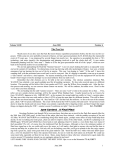
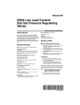
432 AND ABOVE EME NEWS
JUNE 2003 VOL 31 #6
EDITOR: AL KATZ, K2UYH; ENGINEERING DEPARTMENT, THE COLLEGE OF NEW JERSEY, PO BOX 7718 EWING, NJ 08628
TEL (W 609-584-8424) OR (H 609-443-3184), FAX (609-631-0177), E-MAIL [email protected]
PROD/MAIL: BRIAN MULLANEY, KB2TIS (609-883-6390), E-MAIL [email protected]
NETNEWS EDITOR: G4RGK, DAVID DIBLEY, E-MAIL [email protected] (based on K1RQG’s Netnotes)
EME NETS: 14.345, 10 AM ET SATURDAY AND SUNDAY (AFTER VARO NET ENDS ON SUNDAY)
NET CONTROL AND SKEDS CORDINATOR: JOE, K1RQG, TEL (207-469-3492), E-MAIL [email protected]
EME DIRECTORY: http://www.dl4eby.de/, DL4EBY/DK0TU, KLAUS TIEDEMANN, TEL (49-30-7955467), E-MAIL: <[email protected]>
E-MAIL LIST CORD: WARREN, W2WD [email protected] /NL DISTRIBUTION: SCOTT, KD4LT <[email protected]> [TXT OR PDF]
EME STANDINGS: DAN GAUTSCHI, HB9CRQ/HB9Q E-MAIL [email protected] OR SEE HIS WEBPAGE AT www.hb9q.ch.
THE NL WEB VERSION IS PRODUCED BY W6/PA0ZN AND AVAILABLE AT <http://www.nitehawk.com/rasmit/em70cm.html>
CONDITIONS: May Skeds weekend (SW) activity was boosted somewhat by
the Italian EME Contest. Turnout for this contest was not spectacular. This
newsletter (NL) missed promoting it. Propagation was good with the exception
of 70 cm Faraday rotation, which was often near 90 degrees and produced poor
echoes. A May high spot was the appearance FY5DG <Christian.Albrieux
@cnes.fr> on 70 cm – see DL9KR’s report and the April NL. I am sure Chris
will be the source of much 432 activity in the coming months. Unfortunately
planned June 70 cm activity from YL and LY was canceled – see below. The
ARRL’s June VHF Contest is often the source of additional EME activity. This
year’s contest occurs a week after the SW, but is at high southern declination.
Nevertheless it may be fruitful to look for new stations during the contest period.
AB5IG: Lee [email protected] picked up a collapsible 12’ Luly type military
antenna (dish) at Dayton with about .35 f/d. He is lookin g for a V4MA feed for
1296. Lee is planning to try portable EME on 23 cm using an SSB solid-state
100 W amp and TS-2000X.
DF9CY: Christoph [email protected] is getting active on EME again -- I am still
alive, but a little quiet radio wise. I sold all my VHF/UHF gear, except my 8 70
cm yagi array and LNAs. Recently I purchased a VHF/UHF rig (IC820H) and I
will put up a small station for 432 in the future. I have experimented with WSJT
last year on 6 m with some success. Perhaps this is a way to return to 70 cm with
a little lower power than I had 10 years ago. In the meantime I have a family
with my wife Meike and the two children, Christoph and Sarah -- my homepage
at <www.df9cy.de>.I have some gear for sale:
KU4F (loud as usual), G4YTL and DF3RU. Heard were K2UYH (wrong
polarity for EU H pol), EA3DXU (loud with new PA) and OE9ERC. On
Sunday, 11 May, I tested my echoes in preparation for the USA window when
somebody tuned up below my echoes. That station started to call me and I
nearly fell off my chair when I heard DL9KR de FY5DG (559). This QSO
understandably made my weekend as initial #778 and DXCC85. Chris was
puttin g in stable and very readable sigs. I guess this is the second appearance of
FY on 432 after FY7YS back in the mid seventies just prior to my start -up. Chis
will give many guys a chance to work South America after PY5ZBU's QSY to
23 cm. I want to also comment on behalf of Joel, W5ZN’s views on JT44 that
appeared in the last NL. They seem acceptable and should settle the discussion
about the inclusion of "modern" modes into the certification of mixed modes.
"Modern" modes won't be hampered and the efforts of those who stick with the
rough (dinosaur type) modes can be certificated separately as usual.
ES8X: Tom (ES2RJ) <[email protected]> reports that the ES2WX team is going
again this year to KO18XC (island of Kihnu) -- The operating time will be
around 25 July to 5 Aug. Special attention will be focused on 432 MHz EME on
CW and JT44. We will have a better antenna and higher power than last year.
We also will be QRV on 6 m, 2 m and 23 cm JT44. I will let you know when
more detailed information is available and would like to arrange skeds for EME
via K1RQG.
DL1EJA: Oliver’s [email protected] June 70 cm EME dxpedition to YL1A
and LY2AAM is cancelled -- During my final checkout of the 70 cm EME
station, I had a fatal failure of the power amplifier. Because of the lack of time
(we were leaving the next day), there was no possibility to fix it and all efforts to
find a replacement failed. This is a great disappointment. It took months to
assemble of all the equipment and modify everything for EME use. This station
was built for traveling and working EME portable. Thanks to all who helped
with technical advice, equipment and organization. We will try again soon on 70
cm with 4 x 38 el M2 full azimuth/elevation, DJ9BV preamp (NF=0.4dB tested
by DL9KR), GS23B PA (1.5 kW) and modified FT-847.
DL1YMK: Michael [email protected] (JO31qx) plans to be active during the
June SW on 23 cm and will be particularly looking for ZL1KA. Next year he
will be moving to a new location in JO33 where he plans to up grade to a 7.5 m
dish and now has two TH-347 PAs for use there.
DL3OCH: Bodo [email protected] is planning to go to Liechtenstein to try
some additional 1296 JT44 EME tests – see the last NL – I want to go on 29
May, but am flexible. I would consider the 30th, 31st of May or 1st until 9th of
June, if any of these dates would yield more skeds. The conditions are not the
very best, but I allow QSOs with big antenna stations. I will use an IC-706 and a
transverter made by DJ9YW with 100 W output. My antenna is a 59 el yagi.
Later this year I plan to vacation in TK and would like to operate 1296 EME
from there and possibly IS0 in Sept. Another possibility is the T70A club
station.
DL9KR: Jan [email protected] up dates us his 70 cm activity -- In the
EWW Contest (March) I could only be on for 4 hours on Saturday. I worked 34
stations without any initial. However, I added initials on 12 April with DF9RJ
#775 and KI0LE #776 (559). In May, despite poor conditions, which obviously
suffered from the aftermath of an aurora, activity seemed to recover. The
following were worked: on 10 May S52CW, VK4AFL, UA3PTW, SP6JLW,
SK0CC, DJ3FI, UT3LL, JA9BOH, OZ6OL, YU1EV and DL0AO #777 (this is
a club call, operator indeed DJ5RE but at a different site using to my knowledge
4 x FT and 600 W), WB0GGM, K9SLQ (loud), F2TU, RZ3BA/1, S51ZO,
F6CGJ AT F6KHM IN EWW CONTEST (WINDOW REFLECTION)
F6KSX: J-Jacques F1EHN reports on the EWW EME Contest -- The F6KSX
EME group was active during the second part on 10 GHz. Activity was good
only during Saturday evening and no QSOs were made on Sunday. We did not
heard any US stations. All QSOs was made on random and with good reports.
We worked on 12 April12 at 1845 I5PPE (O/O), 1858 OK1UWA (539/559),
1912 DL2LAC (O/O), 1953 F2TU (O/O), 2055 DL0EF (O/O), 2105 G4NNS
(M/O), 2113 F1BLL (559/O), 2200 IK2RTI (O/O) and 2230 CT1DMK (O/O)
for a total of 9 callsigns x 6 DXCC x 100 for 5,400 points. Our station is a 3.3 m
dish with vertical pol and automatic tracking with F1EHN EME System, 50 W
TWTA (40 W at horn), 0.7 dB NF and 10 GHz transverter. We received about
15.6 dB of sun noise and 1.8 dB of moon noise. We believe a separate contest
for the microwave EME is needed to truly boost turnout on these bands.
G3LTF: Peter’s [email protected] May EME report -- I was
active over the Italian EME Contest weekend, but didn’t find many Italians on
the bands! On 432 MHz on 10 May I worked JA6AHB, DF3RU, JA9BOH,
K6JEY for initial #373, OZ6OL, SP6JLW, KU4F, S51ZO, S5 2CW, and on the
11th EA3DXU, SK0CC, UA3PTW and PA0BAT. Condx were good with well
defined polarization. On 1296 on 10 May I QSO’d G4CCH, F2TU, ZS6AXT,
OZ6OL, DK0ZAB, SM2CEW, DF3RU, G3LQR, IK2MMB, N2IQ, IK3COJ,
SM3AKW and WA6PY, and on 11 May LA8LF - really good to hear Anders on
again.
HB9Q: Dan, HB9CRQ [email protected] was QRV on 432 for a few hours
during the May SW -- Conditions seemed to be quite good. See my band-pages
at <www.hb9q.ch> for detailed logs. We will be next active on 7 June 1100 1400 and 1900 – 2400 and 8 June 1215 – 1400 on 144, 432 and 1296.
worked HB9SV (impressive signal!), G4CCH, G3LTF, IK3COJ and ZS6AXT.
On May 11, I just worked DL8OBU and IK2MMB. There seemed to be very
low activity during the Eur window. I have been working on my 1296 feed,
preamp and TX cable (now 1-5/8” Heliax), and I think things are a little bit
improved. I also will be changing the TX line for 432 to 1-5/8" in the near
future.
W2UHI: Frank [email protected] continues to keep the moon warm on
1296. During the May SW he worked DF3RU, G4CCH, IK2MMB, F2TU,
VE6TA, K2UYH, WA6PY, ZS6AXT, HB9SV. He put out a CQ call and was
called by K7XQ, but could not pull him out of the noise and did not complete.
Frank has a new transverter and is looking forward to checking it out on the
moon. See Frank’s web site at http://www.w2uhi.com.
K6JEY: Doug [email protected] (DM03wt) was activity on 432 for
the Italian Contest – I QSO’d on Saturday of the May SW DK3WG (O/O),
G4LTF (O/O), partial S52CW (O/-) and G4YTL (0/0). All three were initials.
Conditions were fair with deep fades. I am redesigning my preamp and should
be able to receive better by next month with N6CA preamp, better relay system
and 1/10 dB loss preamp filter. The system is now 4 x 25 el K1FO yagis, 1.1 kW
PA and a .22 dB NF LNA.
K7XQ: Jeff [email protected] (CM97qi) was QRV on 23 cm for the May SW – I
spent only 1.5 hour on the band on Saturday, starting at my high 20 deg
moonrise at 2230. I worked HB9SV (579) for initial #21, G4CCH (549) and
F2TU (549). Heard were VE6TA, K6DV? and W2UHI. On Sunday I added
N2IQ (539) random Initial #22 and K0YW (539). The system is still my 3.1 m
dish with 150 W from 2 x 2C39 water-cooled PA.
KJ7F: Terry [email protected] is interested JT44 skeds on 70 cm. –- I QSO’d
K2UYH on JT44 during the May SW. Initially I could not copy the JT44. My
clock was so far out of sync that the timing peak didn't even show up on screen.
I can't believe that it took me so long to figure out what was wrong. K2UYH
was speaker copy - very frustrating. I had somehow killed the GPS clock and the
time was wandering all over. Another lesson learned. I just wish that we could
get more of the 432 crowd to try out JT44. It can be a lot of fun.
LA8F: Anders [email protected] is QRV on 1296 again -- I worked on 11
May during 6 hrs of activity F2TU (559/559) - behind trees covered with leaves,
G4CCH (569/569), OH2DG (569/569), JA6AHB (569/559) and G3LTF
(559/569), but did not make it to the NA window. I had a bang from my TH-328
HPA. The TH-328 HPA is now 35 years old, so electrolytic capacitors are at the
end of their life. I have made repairs to the PSU of the Plisch TH-328 HPA. But
as it is very heavy, I have decided to build a new separate PSU. I will put the
cavity in a smaller cabinet, so the 2 units will be easier to move around. This is
the same HPA I used at EA8/LA8LF for 2 years. My new 3.8 m solid 0.325 f/D
dish and VE4MA circular pol feed worked extremely well. Yoshiro, JA4BLC
has kindly sent me some FHX-35LG's and I will make repair to my DJ9BV
LNA, which had been out of service because of a lack of devices. As soon as I
complete the repairs, I will do some CS/G and Sun noise tests.
N7AM: Jack’s [email protected] May 23 cm operation was cut short -- I
worked K5GW and heard a weak one calling me at the st art of the Italian
Contest when I got hammered with a lightning bolt that put my tracking system
out of service. The elevation failed. The problem was the RS232 unit at the
tower. I am now attempting to get things back together here. The WX was good
for the contest. We get very few lightning bolts here. The location of the
lightning crash was three seconds from the tower, so we really got hammered. It
was the loudest crash I have ever heard in 60 years.
NN6T: Glen [email protected] is active on AO40 with a Kenwood TS2000
and a 10’ dish. He is interested in trying EME and wonders if his system is good
enough to hear signals off the moon? [Definitely!] He also has a preamp, but
does not indicate the NF.
PA0PLY: Jan [email protected] is QRV again on 432, but now from
his new shack and is looking for skeds -- During the May SW I worked
OE9ERC and KE2N for initials. I want to sked KO7N, but have lost email
contact with Richard. I hope all is ok? Unfortunately I am currently not QRV
during weekends and must rely on skeds on Monday through Thursday only. I
have finished work on a 23 cm Septum feed and am in preparation for
measurements on an Antenna Test Range.
SM2C EW: Peter [email protected] writes -- On May 4 I completed with
K7XQ for initial #152 on 1296. Unfortunately I was not able to spend the time I
wanted on EME during the May SW. I was on 1296 for an hour on 10 May and
W2UHI’s HOME BREW 5.5 m 0.45 F/D DISH
W4AD: Jack [email protected] in VA (FM18ip) has worked W5LUA for his
initial 3 cm QSO. He has a 10' dish and has recently improved his sun noise
from 10 dB to 14.5 dB.
WA6PY: Paul [email protected] was active on 1296 in May – In the Italian
Contest I QSO’d on 1296 K5GW, HB9SV, ZS6AXT, G3LTF, G4CCH,
W2UHI, IK2MMB, F2TU, K0YW and N2IQ. DF3RU got away. In an extra
sked I QSO’d ZL1KA. Now I need only South America for WAC on 1296. My
5760 transverter is almost ready. I have to finish the 144 switching circuitry and
build an LNA. Then I will test performance on the dish, but I doubt if my
current dish will perform correctly on the 6 cm band. Before the SW, I forgot to
switch off my AZ drive and sent the dish a few turns around the mount. The 7/8'
Heliax feed line was flattened at one place. I made it more round using pliers,
but my return power went up from 0 to 5% of the full power. This is non-linear
scale, so I have to measure it with a network analyzer. I suspect that Return Loss
went up form -30 dB to about –20 db. Probably the best fix will be to cut off the
destroyed piece of Heliax and to use two connectors.
ZS6AXT: Ivo [email protected] was active in the Italian Contest -- On 26
April just after local midnight I worked on 23 cm ZL1KA (549/549) for initial
#188. During the Italian contest I started on 13 cm on 10 May and worked
JA4BLC, F2TU, OE9XXI and G3LTF. There was not much activity, so I
QSY’d to 23 cm and worked JA6AHB, G4CCH, F2TU, IK3COJ, G3LTF,
DF3RU, DK0ZAB, OZ6OL, HB9SV, SM3AKW, SM2CEW, K5GW, G3LQR,
PA3CSG, IK2MMB, N2IQ, WA6PY, VE6TA and W2UHI on the horizon. Then
my EL motor started to play up. I had quite a problem to get my dish into the
park position. On Sunday we were hit by a cold front, so it was impossible to
work on the EL drive. Thus I lost the second pass of the moon. We had very
gusty winds and my other solid dish, which was standing next to the tower, was
overturned. Fortunately the only damaged was just a rotary wash line. Dish is so
strong that it was not damaged. Saturday conditions were very good and my
echoes were coming stronger than I heard them for long time. I received many
(569) and a few (579) reports. This was pretty good for my 200 W. The only
station I heard and missed was HA5SHF. It is a pity the activity was not better.
K2UYH: I added of two initials on 432 and had several interesting JT44 QSOs
on both 70 and 23 cm. On 5 May I ran with VK3FMD on 1296 JT44 after
several failed attempts on 432. Charlie has even a smaller system on 23 cm
where he runs 100 W to the feed of his 20.4 dBd yagi. I received 4 syncs (-28
dB) from him, but he heard nothing from me. This was the reverse of our 70 cm
results. During the SW I worked on 10 May on 432 at 2114 F2TU (559/559),
2125 called DL0AO? (QRZ), but had to leave for sked, 2130 PA0BAT (O/O)
for initial #660, then switched to1296 at 2224 F2TU (56/55) on SSB for a 2nd
band, 2223 DJ9YW (8/11 dB) on JT44 - excellent signal, 2302 HB9SV
(579/579), 2307 W2UHI (569/569), 2312 IK2MMB (569/559) and 2315 partial
IK3COJ – sent QRZ but then realized the call but he quite, on 11 May on 432 at
2230 S53J nil on JT44 sked, 2300 KE2N (559/569) and switched JT44 (9/10
dB) #661 and 2350 K6JEY (569/569), and on 12 May at 0000 KJ7F (8/12 dB)
on JT44 – I could not decode Terry at the start as he was several seconds off in
time. I had a relay fail during my JT44 skeds, but found I could manually switch
between TX and RX and was able to complete my JT44 skeds.
NETNEWS: DL0AO is a Bavarian Contest Club station operated by DJ5RE
and should count as an initial. ZS6JON, Jon [email protected] is
interested in EME on 70 cm and up. N4MW e-mail address is now
[email protected]. NU7Z – Condolences to Rick whose father passed away.
FY5DG is QRV on 70 cm and worked DL9KR on random in May. W9IIX
worked K5GW during the May SW on 23 cm, but heard no one else. He has
now completed the metal work for two GS23B cavities and needs to send them
to get silver plated. W7MEM is not QRV on 70 cm at this time. K0YW worked
during the May SW on 23 cm worked N2IQ on CW and heard K2UYH on JT44.
W7CI is making progress on 23 cm EME. F5VHX has located a dish mount,
but needs to dismantle it before he can ship it home. K5WXN’s move from TX
to Alaska is on schedule. KL7/K5WXN will hopefully be heard off the moon
soon. CT1DMK currently is only QRV on 6 cm and 3 cm. K4AR blew the
center pin out of a Cablewave 1.5/8" connector on his EME array, but now has a
replacement and should be QRV again soon on 432. GM0ONN hopes to be
QRV on 70 cm the 1st weekend in July. He is also working on a 4 m dish.
9H1BN has installed a Septum feed for 1296 on his dish, but lost a 24” actuator
in the process. The dish was not adequately counter balanced. He now needs to
balance the dish and repair the drives before he can be QRV.
FOR SALE: DF9CY has two 7213 PAs designed for the aircraft band that can
be converted for 144 and 432 MHz operation available. Anyone interested
should contact Chris at [email protected]. AF1T has some 10 GHz Qualcomm
amplifiers for sale. They are high gain (over 40 dB) and may be driven with less
than 100 microwatts from a diode mixer. All are tuned up and have SMA
connectors for input and output. They include a power unit to supply +10 V and
–5 V from a +12 V supply or battery. The cost is $US150 post-paid. Contact
Dale at 603-428-3840 or via Lee, AA1YN at http://www.aa1yn.com/vhf.
AA1YN can make 10 GHz feedhorns designed for the Primestar offset dishes.
These horns are bored out to 0.795" and have an SMA (or N) to circular
waveguide transition tig welded to them. W3ZQ has a military surplus AM2066
TRC PA for sale. This is a 400-600 MHz cavity tuned amplifier with rack
cabinet, RF Deck and Power Supply included. It runs a GL6942 final (spare
Included). It takes between 50 and 150 W of drive at 432. This is a twin of the
PA that was used at K3NSS on the 84' dish up until the early 80's. Under an
STA from the FCC they consistently got 3 kW+ output. Pick up only as it is
heavy. Value is around $US800. Please contact Ray, W3ZC. His work phone is
(410)224-0681 or email to [email protected]. NU7Z [email protected] has a
TWTA that provides 65+ W on 13 cm and 55+ watts on 3.4 GHz with about 4 to
5 mW drive for sale. It uses 24 Vdc switching from standby to operation, and
runs on 110 Vac. Including the book for the power supply Rick is asking
$US450 + shipping. VE4MA [email protected] has an 8970 NF meter that needs
work and is looking for service manual. 9H1ES is looking for source of finger
stock. If you know of a source please reply to [email protected]. AB5IG
[email protected] is looking for a V4MA feed for 1296 – see his report. W1ZX
ESTATE has for sale Willie’s 32' dish [24 ribs, feed poles, misc. hardware and
hub]. Also a Bird 43 Wattmeter and Kenwood TS-870. Contact [email protected]
or [email protected].
TECHNICAL: This month we have the first part of a two-part article by
F5VXM [email protected] on his Zero IF Radiometer appears at the end
of this NL. The original article was written for the 2003 French VHF/UHF
conference). Graham writes -- Things have moved on a bit since the original
article. After feedback from folks, I have decided to do a total new PCB
concept. The new this board (currently underway) will have switchable inputs
for 144, 432 and 1296 and will include the necessary helical filters, at least one
gain stage and the detector with it's support circuitry. The output will be a DC
voltage directly from the detector at LIMITED CURRENT CAPABILITY to
drive a meter. Folks will need to implement their own drivers. This leaves the
final DC out available for people to add their own A/Ds. I will probably do a
simplified Micro controller with A/D control and A/D devices. My current one
uses too much high density SMT and in circuit programming for software
upgrades to be easily managed. I'll do a 'pluggable' chip version. This concept
leaves potential users to provide their own additional gain chain ahead of the
'instrument', but it does add a lot of flexibility as many people wanted to feed
transverter chains with 144 IF into something, so this setup will allow either
direct RX gain chains on the 3 bands, or the possibility to use existing setups.
Obviously the accuracy, and especially the drift accuracy, and bandwidth control
will then be thrown into the users court for the rest of his RX chain ahead of
what I design. This is the compromise of stability versus flexibility. The more
knowledgeable users will be able to ensure their chain thermal gain stability and
linearity. The less knowledgeable users will still have a very usable instrument
for good Y factor measurements into the 0.1, perhaps even 0.01 dB areas, i.e.,
very sufficient for proper EME system evaluations. The folks wanting to really
launch into Radio Astronomy will have a base to work from, but will have to
input some effort themselves to get the better stability/accuracy/bandwidth
control. If there is enough interest, I may make some PC boards available later
this year, if not sufficient interest then I'll just post schematics and PCB layouts.
There is now underway a very comprehensive piece of plotting/logging
software, which I will give away as a .EXE running under windows when it is
ready. In all probability this will also interface to my Ulti-track project as well at
www.rfham.com/newulti/index.htm. This will allow heading as well as time
stamp calibration of the X-axis when plotting.
FINAL: This June the International Microwave Symposium www.ims2003.org
will be hosted by my local IEEE section and be in Philadelphia. This is
professional gathering, but many members are also hams and some EMEers. I
have arranged for a "Ham Social" at this year's symposium. The reception is
scheduled for Sunday June 8th from 7:30 to 9:30 pm in the Conference Center,
room 307 AB. If you are in the area, I would like to invite you to attend. The
social is open to all hams. Let me know if you need any assistance.
The 2004 Trenton EME Conference has received its first official registration
from HB9BBD. Although it may seem a little far off, it is really not too early to
start making plans to attend the conference. If you have not done so already,
please check the conference web site at www.qsl.net/eme2004.
HB9CRQ asks everyone to update their initials standing at www.hb9q.ch .
I have been in contact with F1EHN. We are working on organizing a 3 cm
EME contest for sometime next year, probably in the summer before the EME
conference.
There are very few skeds this month. I guess this is a consequence of the
universality of e-mail, but it is still nice to know what skeds are happening
when. If you make direct skeds pass them on to K1RQG for posting on the
master skeds list.
Please keep the reports and tech material coming. My June EME active will be a
bit limited by the Microwave Conference, which begins the same weekend as
the SW. I st ill expect to be on the moon in June. 73, Al – K2UYH
****************************************************************
EME SKEDS
7 JUNE
Time
432.040
1296.050
1100z
ZL1KA -DL1YMK
1900z WB0GGM-UT3LL
1930z WB0GGM-G3LQR
2100z
OZ9AAR-K0YW
****************************************************************
ZERO I.F. RADIOMETER BY F5VHX/G8MBI: This article is an
introduction to an on-going project to construct an Amateur Astronomy
Radiometer. The original idea was to enhance the tools available to me in
evaluating a 4 m dish used for Amateur Moonbounce communication on
UHF/SHF. This article is not intended to be an exhaustive scientific study of the
subject matter, it’s purpose is to highlight the difficulties and sources of error in
what appears to be a relatively simple thing to do, in plain day to day language. I
have deliberately a) not used many traditional , and confusing, scientific terms,
names, & concepts and b) not included many equations & calculations, these
are freely available from many sources. I finally present a new solution (to an
old problem) bought within the grasp of amateur constructors by the onward
march of R.F. chip and micro controller technology.
WHY DO I NEED ONE? One traditional tools for making a judgment about
the performance of an EME system is by use of a ‘Y factor’ measurement. It is
not the purpose of this article to explore all the details of, how, why & when to
make such measurements, but in principal the methodology is to point the
receiving system at an area of Quiet Sky with a low noise temperature, take a
reference reading, then move the system to an object/area with higher noise
temperature, ie, a ‘hot source’. By manipulating the delta between the two
readings (the Y factor) one can reach conclusions about overall system
performance and, by substitution, component parts of ones receiver system. This
process is described adequately in many professional and amateur literature
sources, together with the math and equations necessary. However, they
generally omit to cover adequately the difficulties in obtaining the
measurements and any discussion of the pros and cons within source choices
and methodologies for the measuring process. Although simple in nature and
easily comprehended, in practice Y factor evaluation is rather difficult to realise
with absolute and repeat accuracy. There are two methods that can be used to
make such a Y factor measurement using a typical amateur radio receiving
system. These are shown in following diagrams along with a quick summary of
the methods.
The voltmeter is fed from the audio out of a traditional receiver , there must be
no AGC action in the receiver (this is covered in further detail later)
measurement is made by moving the antenna to the quiet source, noting the
reading, then moving the antenna to the hot source and noting the reading, the Y
factor is then known (remembering of course that 3dB power and 3db Volts are
not the same).
The voltmeter is fed from the audio out of a traditional receiver , in this case
AGC action is undesirable, but if it cannot be switched off then the measurement
is still valid. Measurement is made by moving the antenna to the quiet source,
noting the reading on the voltmeter, then moving the antenna to the hot source
and by use of the step attenuator adjust the signal level until the same reading is
reach. The Y factor can then be read directly in dB’s from the step attenuator.
EASY!!… Yes, but… There are many pitfalls in using this somewhat simple
concept in practice. The first question to be addressed is which sources to use
for the cold and hot comparison. To some extent these choices are driven by the
frequency at which the measurements are to be made. For amateur purposes, and
using amateur budget and size systems the choices are few.
FOR COLD SOURCES: 1)Resistor -You can/could attach a 50 ohm load to
the system and use that as a stable cold’ish source reference. This load can be
switched into the system by a relay, this is quite popular at 144 MHz, the
problems are: a.Temperature/match drift of the load changes noise reference. b.
The different impedance presented by the load and the actual antenna to the first
amplifier stage absolutely ensures that gain of that stage will change during
switching, clearly this is undesirable for accurate measurements. c. Having an
extra relay at masthead to switch the load in and out introduces a degredation to
the overall system noise figure. 2) Ground - The temperature of a non reflective
‘black body’ object is well known, the problems are: a. Few people can realise
sufficient negative elevation to completely fill the array aparture. (especially
with a dish antenna). b. ‘ground’ in peoples back yards is neither constant, non
reflective, or of known temperature. 3) Galactic Quiet Sky…These are areas of
the sky largely unpopulated by noise sources, the problems are: a. At lower band
frequencies (especially 144) the noise temperature of the antenna and hence the
system may already exceed that of the quiet sky. b. The smaller the array, the
larger the beamwidth, the more difficulty in defining where ‘quiet sky’ is. The
temptation is to swing the array until you find the quietist sky possible but in
doing so one does not really know if you are peaking the quiet source or nulling
the other noise contributions.
FOR HOT SOURCES: 1) Resistor surprise! This one shows up in both
categories, the reason for that is that on higher bands the temperature of the load
offers a considerable increase over that of quiet sky. Even at 144, on a large
antenna system, it is possible to measure a negative delta between a load and
quiet sky. The problems are: a. Exactly the same as those outlined in using the
resistor or load as a source for quiet reference. 2) Galactic noise sources
throughout the sky! One can find well documented individual objects and
clusters of objects that are known to be ‘hot’ relative to the general background
temperature of the surrounding sky. The problems are: a. The output from these
objects is rather low on most amateur bands, the traditional choices of
Saggitarius A, Cygnus etc offer reasonable deltas in reading (Y factor)
referenced to quiet sky; at 144 in the 3 to 8 dB range for a typical 4 bay antenna
system, at 432 the array gain is higher for a given physical size and they offer
results in a lower but similar range, at 1296 and up you are required to be able to
measure Y factors of fractions of a dB to be able to use them. b. On lower bands,
especially 144, it may not be possible to find them at all in city or suburban
environments. c. Because of the rather large beamwidths of modest amateur
antennas then the tendency is to not ‘resolve’ the single source that you search
for, but a ‘sum’ of the energy within the large beamwidth. This also highlights
the mostly inadequate pointing accuracy of amateur antenna systems, because
the noise sources are in general, close to or surrounded by other parts of ‘noisy’
sky, the temptation is to peak the noise in the array. This might or might not be
peaking the noise source. It is most likely peaking the best sum available in a
larger portion of sky covered by your beamwidth and hence invalidates the
measurement if any attempt to reference the measurement to the known object
temperature is made. 3) The Sun! Available for large parts of the day in all
locations and offers a considerable hot source with a high Y factor to any chosen
quiet source, makes the sun an irresistible choice for amateur Y factor
measurements. The problems are: a. The effective temperature of the sun at any
measured frequency follows the long term trend of the sun spot cycle, one
absolutely has to know the latest professional data about the state of the sun for
any measurement to mean anything on any band (this has got much easier with
advent of internet near real time data availability). b. Within the long term trend
of the sunspot cycle there are much shorter term deviations, these sudden storms
and outbursts can cause considerable deviations over seconds, minutes or hours.
c. Because the temperature being measured is so much higher than any chosen
quiet source then the measurement requires a receiver with good linearity over a
largeish dynamic range and no AGC action to eliminate gain change errors
being introduced. d. Most, if not all, amateur sun Y-factor result calculators are
rather inaccurate or just plain wrong!! This came as somewhat of a surprise,
during 2001/2 when Doug VK3UM decided to revisit the subject and construct a
new Y factor computer tool. I and a group of others contributed to Doug’s
project with research of existing tools and more fundamentally into the
equations needed and their implementation as well as cross checking results
from Beta software releases with actual system measurements.
It soon became clear that many existing implementations were primitive. Some
discounted or did not allow, input of major system parameters, most had no, or
poor, documentation. For example they demanded input of Solar Flux, but gave
no hint of which solar flux. Some just simply implemented the well known
equations wrongly. Just about all made no allowance for spectral content in the
suns output and for the different bands attempted a ‘straight line’ approximation,
if they bothered at all!! Doug’s final effort can be downloaded from
http://www.qsl.net/sm2cew and as well as Y factor handles moon budget and
radiation compliance calculations. It has now been tested by a good number of
stations worldwide who make credible measurements and offers good
correlation to those measurements. It has been repeatedly ‘blind’ tested at
F5VHX on 1296 MHz and accuracy is within +/-10 to 15 SFI numbers. (2800
MHz SF is the data used). 1) Ground can be used as a hot source to reference to
quiet sky. The problems are the same as those as using it as a quiet source
outlined above. It is not my purpose to discuss in further details the difficulties
and correction strategies for ALL the above choices, this would inevitably lead
to a detailed, long and complex, analysis of several entire systems. Instead I will
summarise the situation in two simple and common choices and highlight the
challenges they present to the receiver & measurement systems (only) outlined
in the diagrams of the standard two methods available.
A. USE QUIET SKY TO SUN. This offers a large delta to measure (big
difference from low temperature to high temperature) and so in many ways and
on some bands is the only viable measurement that can be made by amateurs
Leaving aside the difficulties of the actual calculation and correction factors
already discussed, the receiver only challenges are: Method 1. You need a
system linear over the necessary measuring range, this can be as little as a few
dB on 144 with a modest antenna but as much as 20+ dB on 1296 with sizeable
dishes. Clearly this means that any in built AGC action of the receive system
must be switched off entirely, it also means that ALL gain stages must be linear
and not subject to degradation of noise, this is very improbable in a modern
narrow band receiver. In addition you need to increase the integration time in
order to have a stable ‘average’ milli-voltmeter reading, in most cases this is not
easily achieved either and you end up studying either a blur of numbers on a
digital meter (really unsuitable for this purpose) or a fluctuating needle on a
traditional meter. You also need a large scale meter with good resolution, and
because of the large ‘swing’ with measurement, most likely some attenuator or
‘range’ switching in the milli-volt meter itself. Such meters of good professional
quality can, however, be found from time to time on the surplus equipment
market. Method 2. System linearity requirements are easier and AGC actions
have less or even no influence, the difficulties of integration time and milli-volt
meter ranging remain. The biggest challenge however is locating suitable step
attenuator(s) that are rated at the required frequency and offer the necessary
precision within switching steps. Once again one is faced with possible ‘match
gain’ changes for each step if the impedance is not very close to constant. Whilst
one dB step attenuators can be found on the surplus or used market, to find
fractional dB step models is very hard.
B. USE QUIET SKY TO NOISE SOURCES (such as Cygnus, Sagg A etc)
This method requires measurement of much smaller deltas or Y factors. Method
1 and Method 2 require stable milli-volt meter readings to resolve the small
changes to be measured, and in addition, method 2. requires a fractional dB
precision step attenuator. At lower bands one has ‘some chance’ to take these
measurements. On 144 you can be dealing with “a few dB”, at 432 one is
dealing with typically 1, 2 or 3 dB on most more modest amateur antennas. At
1296 and up one is dealing with fractions of a dB. Some people use a hybrid of
method 1. & 2 for these measurements using a 1 dB attenuator step to reduce the
linearity/agc requirement and then trying to take the final fractions from the
meter. This is the right moment in the discussion to raise the issue of
‘Bandwidth’. In small noise temperature change measurements then bandwidth
can be your friend. Wider bandwidths at detection stages offer the possibility of
greater resolution. The structure of a modern amateur transceiver is in fact, in
many areas, in conflict with the requirements for making good Y Factor
evaluations. The modern transceiver is more generally targeted at narrower and
narrower bandwidths as this improves efficiency for working with signals, it is
also targeted at handling larger and larger dynamic ranges (differential between
the smallest usable signal and the largest it can cope with) however it often does
this is an increasingly less flexible manner. Many modern transceivers do not
offer the facility of being able to turn off entirely AGC and other actions. They
also may not be coping with signal level differentiation in a truly ‘linear’
manner. As more , and better, DSP techniques and components arrive, this
situation is likely to get better and better , from a signal handling perspective,
which is what they are designed to do, but perhaps worse and worse from a
noise measurement perspective. As DSP moves into the IF and further (?) then
we are further and further removed from the opportunity to really ‘know’ the
relationship of what goes in the antenna socket to what comes out of the speaker
socket!!
SUMMARY SO FAR. For making repeatable and reliable noise (temperature)
Y factor measurements one needs good linearity, possibly over several tens of
dB of dynamic range, with larger gain bandwidths if possible and stable gain
over at least tens of minutes time scales, with a broad bandwidth detection stage,
all targeted at offering fractions of a dB measuring capability and readout.
SOLUTION? These requirements have been well understood and well solved in
recent history by professional Radio Astronomers. It is beyond the scope of this
article to explore all the possible solutions, I just want to clearly state that the
solution I have arrived at is not new, revolutionary, or breaking much, if any,
new ground. Many have been here before and those dedicated to Radio
Astronomy have gone much further. My approach has been to take a
fundamentally sound principle and try to simplify it by exploiting modern
technology and specifically new R.F. chips that have become available in the
last couple of years. Currently my solution is for 1296 MHz, it is rather easy to
change for any band by simply changing the three 2 stage helical filters
employed to ‘define’ the band of use. (In fact it may also be necessary to change
slightly one or two stripline inductors and matching sections/components,
experiments to move this design to 432 MHz and are underway). The increasing
high frequency capability at low cost equation of these new parts means that one
can take a much simplified approach to designing and constructing a ‘noise
receiver’. It is now possible, for a few tens of dollars, even at what have been
thought of traditionally as very high frequencies to work with, to take the band
of interest directly from the antenna element to the detector element and with no
need for narrow band signal separation or complex modulation detection that
demand ‘messy’ frequency transformations, filtering, alignment and strategies to
stop these more complex elements degrading the required stability parameters
we need. - KISS (keep it simple stupid) has got even easier for the solution to
this problem.
WHAT DOES IT LOOK LIKE THIS ‘NOISE RECEIVER’? I will now
describe my solution and the progress so far with some practical results. This is
not a simple construction article of the “here it is, build it” variety, it is a
presentation, discussion and explanation of the concept, the current
implementation, the pitfalls and failings which will hopefully provide inspiration
or a ‘route map’ for others wishing to go this, or a similar, way. Before I present
the electronics content, here is some data generated by it to wet the appetite a
little with what is possible. The plot (below) was one of the earliest practical
results from my Radiometer, although primitive by professional yardsticks it
clearly demonstrates the usefulness of such a tool in evaluating one’s radio site.
This plot shows very well the challenges that can be faced operating EME at
1296 MHz at low elevations. Some of the objects identified are at large
distances from the dish, for example the object identified as “two trees alone”
are 150 metres away. The object “stone tower on hill” is over 300 metres away
and offers only a small dish aperture fill at the 5.5 degrees of elevation that the
scan was made at. It also shows the difficulties of deciding what is ‘ground
tempera-ture’ if you wish to use that as a reference, it can be clearly seen that
the wall of trees to the west of the dish offers a higher temperature than the
shack concrete wall, even though the shack wall is much closer to the dish itself.
Obviously reflectivity plays a large part here. The wall of trees to my west
displays a range of readings depending on season and if they are wet or dry. The
scales used in this plot are far from either clear or desirable (!!) They were
concocted before I developed a little more sophisticated PC software to
command the radiometer and collect the results, the antenna was driven by hand
one degree at a time and each point laboriously noted by hand, before entering
into EXCEL for analysis and plotting. As will be seen later I have since largely
automated this process although there is much left to do
THE ELECTRONICS Although I do have access to decent CAD tools for RF
simulation, schematic capture and PCB design, this project has been undertaken
and constructed using not much better than ‘kitchen table’ tools as far as pcb
manufacture and soldering etc. is concerned although having access to a good
network analyser for my initial experiments and tuning and matching of my gain
strip has proved invaluable. The heart and the inspiration for this project is a
detector chip designed for professional power measurement and control from
Analog Devices. This chip first appeared during 1999 and I subsequently
became involved with it on a semi-professional basis in the implimentation of a
micro controller based power meter application. This AD8313 chip has been
designed to translate rf input to a proportional DC output. The output offers a
variable slope voltage, I have set it for 20mV. Per dB of input change. The
minimum detection level for the chip is around –70 dBm. and the quoted
dynamic range is 70 dBm. for 3dB output accuracy, the second figure quoted is
a 65dB dynamic range within 1 dB accuracy at 1.9 gHz., various ‘typical’
graphs and plots are avaialable on the full data sheet available for download at
the Analog Devices website. Having a cheap , simple and apparently reasonably
accurate ‘detector’ it is then necessary to provide some gain ahead of it along
with some band filtering, as well as some method of extracting the resulting DC
output and reading or displaying it. Before discussing my choices for those
sections and why, here is the basic block diagram of my Radiometer design. I
will work through these one at a time with a quick outline of component
choices, experiences and final results.
MAJOR DESIGN DECISIO NS To use Surface Mount Components and
techniques throughout, this is in any event forced upon you as most of these new
devices are only available in smt packages, it also happens to be my preferred
method nowadays. It offers greater reproducibility in no tune designs and also
allows mostly single sided board occupancy and tracking which is easier to
handle on prototyped boards without full plated through holes. 1) To house the
various stages in tin plate boxes. I would prefer to house these in milled
aluminium boxes and may do so at a later date. I chose the tin plate based on
availability, cost and the fact that this current model is really a ‘test piece’ so
throwing away non-working revisions is cheap also. To achieve sufficient
stability (mechanical and thermal) for the Radiometer to be useful as a radio
amateur station measuring tool was also a consideration, to push the techniques
further and target better resolutions required for a more pure Amateur Radio
Astronomy solution probably does demand better housings. 2) To use fibreglass
PCB material where possible I have little concern for losses, other than in the
LNA where I used Teflon. FR4 material is cheaper and more easily available to
than Teflon types. 3) To use stripline matching and other techniques where
possible. 4) To design/build each module as a total stand-alone unit, that means
it’s own 5v regulators RF in/out connectors etc. This modular approach allowed
some sections to be discarded and redesigned initially and has now provided a
kind of building block approach where various sections can/could/will be used
in other projects.
INTRODUCTION TO THE THE VARIOUS MODULES.
To be continued
Bottom of LNA view where the 2 stage helical filter is, the holes to the left of it
are for another filter which I have elected not to fit at this time.
Top view of the 2 stage LNA. Input is on the left. The line up here is an
ATF54143 front end input stage, this was chosen because of it’s exceptional IP3
performance and easily achieved low noise figure characteristics, full active bias
is employed, it feeds, through a 2 stage helical filter, to a second stage
comprising of an Agilent MGA53543, this second stage was again chosen
because of it’s IP performance, noise figure & small physical package. There is
option on this board to add a second filter after the MMIC, in this picture you
can see it has been ‘jumpered’ out with a short length of coax. The final
performance of this LNA is an NF of 0.3-0.35 dB with a total gain of around 30
dB. The filter provides an impressive roll off, below is a picture of the low side
of this shape (the high side is close to symmetrical)