1
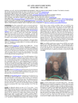
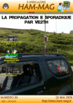
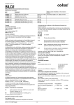
The first free & monthly E-magazine for amateur-radio, SWL... 4 U 1 V I C i n WA E S S B c o n t e s t 2 0 0 8 FT290 SECOND LIFE Z A Ø DX ' P E DI T I O N Number three ! H AM MA G ISSN N.17606470 The Hall of Fame Donators of february PAØNCV, Nick K6LCS, Clint Richard Downey VK2ETA, John Laurent Horne K4SHF, Tim KE4IAP, Don K3PB, Pat W2FBS, Richard VK2SJJ, Steven CT1ADT, Manuel KB1KRS, Hyrum 2IØCOS, Cornelius KA5DON, Don PY3ARS, Jocarli W3ACO, Rich NØAX, Ward MØWAY, wayne Antonio de Armas Medina K3ZIV, Bill Milan Puncer William Beyrer EA6BB, Pedro W1CRO, Arthur KA8Q, Jerry Thanks a lot four your support ! To be in the hall of fame, visit our Website and click on "help us" http://www.hammag.com THE RACE WITH OBSTACLES By Francisc Grünberg, YO4PX I started to read with great excitement the article written by YO2**, dedicated to the 40 years anniversary of the radio club of Timisoara, my beloved place of birth, abandoned by me 37 years ago, but on whose streets I still walk often in my dreams. There I brought up and went to school, there I traveled in frosty winter mornings, when the mercury of the thermometer descended under 20 degrees C, sometimes on the foot board of the crowded streetcar 6, on its circular way, through the Maria plaza and on the bridge over the river Bega, trying to arrive in time to the Musical High School situated in the downtown. But I haven’t imagined in my nastiest dreams that reading this article I will come across again with «comrade» Alexandru, albeit only under the spiritual shape of a name printed on paper. Like in a nightmare, comrade Alexandru reappeared in my life, though I was hoping once that I’ll may erase him for good from my memory. The author of the article is arrogating him good organizers’ abilities who knows, maybe he was really a good organizer but for me he was the one who for two lengthy years prevented the fulfilment of a dream. I was 16 when a class mate, a violoncelist inoculated me with the bug of amateur radio by giving me a few issues of the The Radio Amateur magazine and revealing me the «secret» that on the short wave bands, amidst the broadcasting stations one can hear radio amateurs ragchewing freely, something fast unconceivable to the spectators of the propaganda films of those years, in which the only ones operating radio stations were either brave Soviet soldiers, or spies, disgusting traitors in the service of the Western intelligence agencies, who ended always by being caught, thanks to the patriotism of a pionier or a Comsomolist (member of the Soviet Young Communists’ organization), who discovered their activity and informed the authorities. I found quickly in our rudimentary radio set the 40 and 20 meters bands and, amazed, I started to listen the QSO’s of the local amateurs and of the foreign stations in AM, among them many Italian stations, with their extremely strong signals. Then, with the help of an old scout guide I learned by myself to copy the CW contacts too; obviously the signals didn’t have a musical sound, they were only «buzzing», and I remember the thrill felt when I heard in a very early morning the trembling signal of a W6 station sending QTH CA and then a Chilean station from Antofagasta. I even manufactured log sheets, keeping record of my receptions and I started to dream that one day I will send QSL cards bearing my SWL callsign! In the winter of 1959 I entered my name for the telegraphy courses organized by the A.V.S.A.P., the «Voluntary Association for the Defence of the Homeland», held in the main room of the radio club and I graduated them in the summer of 1960. I became also the happy owner of a fabulous booklet with gray covers, the Radio Amateur Traffic, from which I learned a lot of new things. It comprised the list of the DXCC countries, their prefixes, their CQ zones. After a few months I knew most of them by heart, many of the prefixes appeared already in my «logs», so that when a member of the examinations commission for the amateur radio certificates asked me about some European prefixes I had no trouble at all to give him the right answers. In November 1960 I became the proud bearer of the Amateur Radio Short Wave Listener Certificate No.184 and I filed together with my telegraphy courses colleagues the application for the SWL License. Everything seemed to be all right, nothing foreboded the enter of comrade Alexandru in the scene and in my life, to overshadow the enjoyments of my young years. I haven’t seen him very often before, in the afternoons when the telegraphy courses were held I could admire only the skill of a few amateurs constructing in the room on the right side an enormous station, while in the room of the left side the legendary Mir, YO2CD was busy with his exotic CW QSOs. It was said that the new radio club chief is coming from the Army and that he has no idea about amateur radio whatsoever. Well, this haven’t prevented him to reject my license application, while the other applicants among them Hungarians and Germans besides Romanians, but none of them Jewish received their licenses and went off hastily to the workshop to order the stamps with their brand new SWL call signs. Alexandru was supported in his categorical verbal refusal like in all other his actions by a wellknown ham from Timişoara, today an oldtimer, who was shaking his head and shrugging enigmatically his shoulders alike the «boss», as an answer to my desperate questions. This was the beginning of a tormenting time, marked by permanently renewed and afterwards unfulfilled expectations. Alexandru hoodwinked me, appointing time and again new dates when I had to present myself to the club, and I remember the winding staircase mounted by me with pang and hope and descended soon full of sorrow, having in mind a new date when who knows, maybe, possibly, nevertheless a misterious and unseen guardian of the Law, arised out of the writings of Kafka, will finally take pity and will agree with the supplication of the poor unlicensed short wave listener, who desired so much to be within the Law…… I have kept record of these visits to the radio club. They were as much as 35. At the thirtyfifth visit Alexandru, probably bored of the monotony of this repeated scenario, opened with soldierly courage a new battlefront: one has to be member of the UTC (the Union of the Communist Youth) to become a licensed short wave listener. The homeland has confidence only in UTC members. I objected: among my course colleagues who obtained the license I know a few who are not UTC members, some of them didn’t even reached the necessary age to become UTC members. Alexandru sank for a while into his thoughts, but at last he found the saviour solution. A letter of reference from the school, that’s it, I need to obtain a letter of reference from the school, but for this we’ll go together, comrade Alexandru and me, to request the letter of reference from the headmaster. As a disciplined military man, he was waiting for me at the entrance of the high school on the appointed day and time, wearing his greenish uniform; in front of the headmaster’s office he told me to stand by and he stepped in alone. The headmaster was very fond of me, I was always included in his «troupe» of studentartists, able to perform a complete musical programme, sent by him to take part in all the artistic festivals held in the county, and with my xylophone, accompanied by a colleague at accordion, I scored fulminant successes. I’ll never find out what exactly they discussed inside the cabinet, the fact is that after a time Alexandru came out and showed in direction of the door: the headmaster is waiting for me. This entire suspicious theatre seemed to be of very ill omen. With burning face and stammering of emotion I presented to the headmaster my grievance to be issued with a letter of reference. As long I live I’ll never forget the profound embarrassment of the poor man, constrained to deny my request, without being able to offer me any explanation at all. I left astounded the cabinet. Alexandru disappeared. And with this all my hopes collapsed. I decided to give up irrevocably to this hobby, which for me seemed to be forbidden. But before that I’ve done however something: for the first time in my life I exercised my right of petition, granted by the Constitution, in my capacity of young citizen of the Romanian People’s Republic. I wrote a long letter to YO3**. I heard him Sundays transmitting on 40 meters band the official QTC’s of the Romanian Amateur Radio Federation, and I thought that somebody must nevertheless learn about the mockery I’ve been inflicted, it must remain somewhere a trace of it. I counted him day by day the 35+1 summons to the club and I asked for his help, simply unable to understand why I have been refused to get something obtained by others without any difficulty. I sent one copy of the letter to the Central Radio Club, another one to his personal address, I found both addresses in the telephone directory. A few months I still watched the arrival of the postman. In vain. The Romanian citizens’ right of petition was laid down all right by the Constitution, but not so the obligation of the institutions or the officials to give them an answer. Probably that’s why the addressee did not condescend to reply to my S.O.S…… After a year or so I came across on the street with a course colleague. He received already his transmitting license, he told me that he worked ZS4 on 40 meters. And he gave me another information: comrade Alexandru was called back to active service, the new chief of the radio club is Costi Dumitrescu, YO2BI. Go to the club, he’s a good guy, maybe he’ll give you a hand, added the colleague before we gone apart. I ascended with trembling feet the wellknown wooden stairs. And indeed: in the room tapestried in blue by comrade Alexandru, near the station sate a nice looking young man. I narrated him in short what I have been through and I showed him my SWL certificate. He smiled sadly, sympathetically, then he rose to his feet, extracted from a locker a form, he filled it in with my name and with the «receptionable bands» in my poor radio set: 7 and 14 MHz. Then he consulted a register and he filled in also the «call sign» column: YO21117. Go to the Central Post Office and ask them to stamp it, he said. Then he turned to another ham present in the room: Unbelievable, isn’t it? After a month I was there again, this time with about 300 QSL cards, my very first receptions as a licensed SWL. I brought with me the log copy as well probably the younger colleagues doesn’t know that in those years one had to present carbon copies, even for receptions, in order to be verified by the «authorities». Costi run over the pages and he said: Wellwell, how nice would be if the transmitters could keep their logs as orderly as this one! With this a chapter came to an end for me, but not so the ordeal of my race with obstacles. I reached its finish only in 1980, after 17 years of formfillings, applications, petitions, remonstrances, memorials … and receptions. I obtained my transmitting license at the age when other hams accumulated some 20 years of activity. This is the way I’ve acquainted comrade Alexandru. I hope with my whole heart that on the way of their evolution our younger colleagues won’t come upon such characters, who were able to do much harm to the Romanian amateurs, in those years plagued by arbitrariness and totalitarianism. This text was published in the Romanian magazine Radiocommunications and Amateur Radio and on the independent website www.radioamator.ro 73's ! YO4PX 4U1VIC in WAE‐SSB contest 2008 BY OE3SGU ‐ Hannes Every 2nd weekend in September the SSB part of the „Worked all Europe“ contest takes place (www.waedc.de). Normally stations located in Europe may only work stations located on another continent, but this year because of the 60th anniversary of the WAE diploma an exception was made: Europeans could also work other Europeans. Of course, no contest points were granted for these contacts, but the t fun taking part in the competition was greatly improved. This fact was enough reason for some hardcore shortwave enthusiasts (Günther, OE3GCU, Werner, OE1DWC and Hannes, OE3SGU) to think about participating from the UN Headquarters in Vienna, the Vienna International Centre (VIC). 4U1VIC counts as a separate region and multiplier in this contest and thus we expected some nice pileups. It also has been a while, since a multioperator group has operated from the VIC. We soon thought about how to best realise this project. After we established contact with some Hams from the VIC, ten days before the event all of us met and discussed the details, and we had a look at some possible contest locations. We wanted to plan everything as thouroughly as possible in the short time remaining – making the best out of the given facts and options. Soon we realised, that participating during the whole 48 hours of the contest would not be possible. Security standards in the VIC require, that a UN staff member be with visitors during the period of operation. Furthermore, access to the VIC during the weekends is only possible in a very restricted manner and requires an early registration. Thankfully, Rom, OE1RKS, Alex, OE1AWB, Bernhard, OE3BLB and Rainer, DL1DTN – all employees at the VIC – offered to stay with us during our contest activity. Needeless to say that this is not a matter of course as normally all rather like to spend their weekends with their families instead of at their QRL’s location. A short visit and inspection of the present shack of 4U1VIC in the Gbuilding near the “Austria Center“ conferencebuilding soon showed us that there is relatively little space for wire antennas. Even OE1DWC and OE3GCU installing a beam would not be an easy task. Also, the Gtower “only“ has 48 meters of height and transmission into some direction is severely blocked by some of the higher UNbulidings around. Among other offices, the Gbuilding accomodates UNIDO and IAEA. On the other side, building “D“, seat of UNIDO and CTBTO, is a massive 102 meters tall and offers a relatively free sight into all directions. According to Alex, OE1AWB, a temporary weekendoperation from the Dtower would be possible. He could offer us a little room on top of the roof that is normally used as a serviceroom for elevators. The room offered just enough space for the group and sheltered us from any outside noise, wind and rain. Friday before the contest the antennas had to be installed. We used a Cushcraft A3S tribander (lent by Georg, OE1GPC) including a SPIDrotator (from Manfred, OE1MB) for the higher bands. For 40 and 80 meters we had monoband dipoles which were adjusted by Günther, OE3GCU, for a perfect low SWR. Installing the antennas was more difficult as we expected and took until sunset. A total lenght of 130 meters of coaxial cable was needed. Günther and Werner really had planned every little detail. There was literally nothing they had not thought about. Every adapter and tape, every screw, an SWRanalyzer, ropes – all had been brought by them. For enabling us to install the A3S at the ladder on top of the roof some special brackets had to be built. The exposed – and sometimes very windy – location on top of the Dbuilding offered a phantastic view all over Vienna and to parts of OK and OM. This location was a dream for someone whose options in installing outside antennas are very restricted or nonexistent. The radio in use was Günthers’s Icom IC775DSP, including a Heilheadset, a footswitch and a microHam microkeyer. Werner brought along his OMPower 2500 linear amplifier. With a modest drive of 20 watts this linear delivers a massive Kilowatt output – just what we needed for the rough contestuse. All the logging was done by „WinTest“. We were on the air for a total time of approximately 20 hours. On Saturday we worked from 0755 to 2245 and on Sunday from 0710 to 1655 (local time). Late in the afternoon on Sunday we started disassembling the antennas and evacuating the equipment. Only a very modest operation during the nighttime was planned. We worked in shifts of 2 hours which proved of value as it gave everyone some time for other obligations. Unfortunately, band conditions during this weekend were absolutely disappointing. In the morning we only had smaller pileups, mainly with European stations on 40 meters. During these times of low activity we mainly “searched and pounced“ the bands for new multipliers. Probably only a few European stations knew that this year they could also work other Europeans. Most of the callers came from outside our continent. In the afternoon, 20 and 15 meters often provided A3S antenna on Dbuilding wide openings and we finally could change into “running“. Especially on 20 meters we had nice pile ups to NorthAmerica and to Japan. Many W6/7’s, VE’s and JA’s/HL’s had big signals over S9 and queued to work us. Interesting entries into our log on 20 meters were stations from 5R, 9K, 9M2/6, BY, EY, HI, HK, TI, TR, TU, UK, VU, YB, YI. 15 meters partly showed nice signals from Near, Middle and the Far East, but most openings only were of a short duration. Among others, we were able to work stations from A7, HS, HZ, JA, UA0, UN, YB. 40 meters opened to South America; the prefixes HI, HK, PY, YV could be logged. But we also managed to work 4L, 5B, EA8, EA9, JA, TA, UA0, VK und some W’s on this band. All QSO’s of this activity – as it is a tradition with 4U1VIC – will be automatically confirmed via the bureau. Of course all direct cards will be OE1DWC and OE1RKS answered, too. We will also upload our log into the ARRL’s Logbook of the World (NOTE: ONLY contacts for this activity! All other, earlier QSO’s of 4U1VIC are not available in electronic form!) A special thanks to all of the UNstaff who supported and accompanied us patiently during this contest. Thanks to Rom, OE1RKS, Alex, OE1AWB, Bernhard, OE3BLB and Rainer, DL1DTN – without you it would have been impossible to realise this project! Our thanks goes also to the very patient security staff, who assisted us in checking in and –out the pile of boxes and antennas and tolerated our presence during the weekend. Last but not least: thanks to our partners who gave us a free weekend for our hobby and to everyone who called us. We are looking forward to the next QSO in the next contest or during the next activity of 4U1VIC! QSOstatistics for 4U1VIC 13/14.9.2008: A total of 1027 QSO’s with 80 DXCCentities were made, on 80 m: 3 40 m: 238 20 m: 763 15 m: 23 10 m: 0 0,3% 23,2% 74,3% 2,2% by continents: Africa: Asia: Europe: North America: Oceania: South America: 16 135 399 453 5 19 1,6% 13,1% 38,8% 44,1% 0,5% 1,8% claimed score: 173756 © Hannes Grünsteidl, OE3SGU ([email protected]) OE3SGU on top of the building View over Vienna from the shack A NEW LIFE FOR THE FT-290R TRANSCEIVER ! By F5RCT The FT290R is an old amateur radio workhorse which was a very popular transceiver during the 80’s. It is a 2metre multimode portable which can run with or without an external 12 V power supply unit. Still quite favoured as an exciter for transverters or linear amplifiers, it is built like the proverbial brick outhouse. Large numbers were sold and they are now commonly available for around 150€. They seem to be reliable in general and most components are discreet and can be replaced. The following article proposes a list of modifications “à la carte” to improve their performance. The Yaesu FT290R is a multipurpose, multimode FM / CW / USB / LSB portable 2metre transceiver. With 13.8 VDC input, output power is 2.5 watts. Coverage is 144 to 146 MHz. FM steps are 12.5 or 25 kHz for the European version. CW/SSB steps are 100 or 1000 Hz. It has a builtin telescopic antenna. The radio operates from eight alkaline/NiCad C cells (not supplied) or from an 8.5 to 15.2 VDC power supply. It measures 6 x 2.5 x 7.9 inches (150x58x195mm) and weighs 1.3 kg. For modifications you need the schematic diagram and the alignment procedure described in the user manual [1]. The minimum equipment required to align the transceiver is a power metre and a frequency counter (or better: a spectrum analyzer). I have tested four devices: on some of them PLL and SSB modulator frequency crystals drifted due to ageing. Aluminium capacitors had aged too and showed an equivalent series resistance of more than 3 Ohms on 10µF capacitors. Some of them can leak, block the AGC line and have an effect of “heating up” when power is turned on. Internal antenna removal and Pi filter improvement: The FT290R has a reputation of low sensitivity when the transceivers from the 90s came on the market. Mutek Ltd offer the SLNA290s [2] preamplifier but the internal antenna system will bring losses anyway. This present modification has two advantages: It reduces the loss on the system by 2dB, improves the output power (x1.5) and sensitivity is better. For OMs who don’t like the antenna socket connection at the back, it is possible to replace the antenna by a BNC socket on the front panel. Removing the inserted ring can be done by drilling it carefully through with a 10.5 mm diameter tool. On one device, I used the hole to place a 3.5mm stereo phone socket. Very useful for common headsets! The output Pi filter shows losses and needs to be modified. Remove the antenna and the tube along the flange and the components wired to the main board. Remove all external components located outside the main PCB : From small tore L02 to L01. It is possible to replace the capacitors with 1206 or 0805 SMD 50V COG soldered directly on the bottom of the board. : it’s easier and quicker than removing solder from holes. Now replace C106 (33pF) to 22 pF with a good ceramic capacitor (located in the corner near the screw). Replace L12 with 6 turns on 3 mm diameter using 0.5mm enamelled wire. Add a 39 pF capacitor between L12 and L13 (a location is foreseen). Add a 22 pF capacitor parallel to D25. Replace C101 with a 470pF to 1 nF capacitor. Reassemble the turns of L13 as shown on picture. The Tx output stage needs to be tuned. Select the high power switch position. Adjust VR2003 to maximum power, and then adjust TC05 and TC06 to maximum power at 145 MHz in FM mode. The current is approximately 1.1A at 12.5V and maximum power is 4.5 W on my sample. Then reduce the power to 3.5 W by adjusting VR2003 again. This is necessary to stay linear in SSB mode. Select low power switch position, and then adjust VR2006 to 500 mW. The insertion loss on Rx is improved from 2.7 dB to 0.7 dB. On Tx the loss is improved too: from 2.5dB to 0.6dB and allows more than 1W in additional power.). Using the FT290 as a transverter or a PA: The FT290R has two power levels: 2.5W and 500 mW. The low power mode may only be used for power consumption reduction. In low power mode ALC is not working and modulation compression is not present. The low level depends on a gate voltage of the Tx IF chain, this will imply large tolerance on this level, depending on temperature and frequency. To use the transceiver with a PA or a transverter I recommend using it in 2.5 W mode. It is possible to adjust the level with VR2003 down to 1 W. Receiver sensitivity improvement : Sensitivity of initial circuit with modifications of Pi input filter and internal antenna system removed. Connection direct to S0239 antenna socket: 120 dBm measured (0.22 µV) at squelch threshold in FM with CW signal. 115 dBm measured (0.39 µV) for 20 dB (S+N)/N in SSB with CW signal. (0.5 µV specified on datasheet). The poor sensitivity comes from different design reasons and from the input transistor: Antenna switching from antenna socket to receiver input has high loss. The last modification reduces the loss by 2dB. The input transformer T01 has loss too. Having a transformer with very thin winding wire introduces loss compared to a direct matching circuit. The input transistor Q1001 has a poor noise figure even if the gain is sufficient. A quick modification consists in grounding the source resistor to increase gain (+1 or 2 dB) and drain current: but there is no improvement in sensitivity (signal to noise). This will increase G2 voltage and gain. This transistor is located close to the power jack. Desoldering of T01 is easy by using a large tip and adding a lot of solder tin to heat all leads together. Remove Q1001, C03, and C07. Clean holes with a desoldering pump. Replace Q1001 with a BF988 soldered on back side with reference facing the PCB. It is possible to use a BF690, BF961 or BF964 (or the SMD versions: BF998, BF994, ..) Remove carefully the shield from T01 and the ferrite cap, cut the wire and clean the coil support. Then T01 is wound with 4.5 turns of 0.25 mm enamelled wire. Start the winding at the top second slot from G1 pin connection to finish at ground connection. Place the 6pf or 5.6pF capacitor from ground S to G1. Add a 4.7 pF capacitor from G1 to input close to C101, or replace C101 with 4.7 pF and make a short jump to G1. Solder non used pins of T01 to ground. The front end stage T01 and T02 need alignment at 145 MHz using an RF signal generator, based on maximum deviation of Smeter. Tests: Sweeping the stage from antenna input to output of T02 gives a gain of 23.5 dB. The AGC voltage of 2.1V is sufficient to get the maximum gain. 123 dBm measured (0.16 µV) at squelch threshold in FM with CW signal. 118.6 dBm measured (0.263 µV) for 20 dB (S+N)/N in SSB with CW signal. With 128.6 dBm measured (0.083 µV) for 10 dB (S+N)/N it is possible to decode a good CW signal. The sensitivity measurement shows a 2.6 dB improvement, with the modification of the Pi filter it is about 5 dB better! Calculating the approximate noise figure from output S/N to input S/N: NF = (128.6 dBm) – (174 dBm/Hz + 10log (2400 Hz) + 10 dB [(S+N)/N] )= 1.6 dB (Not bad!) Modulation improvement : If you have a low pitched voice and reduce plops effects it is necessary to cut off audio low frequencies by changing some capacitors. This modification improves the quality of modulation by cutting low frequencies under 300 Hz. A slight emphasis of 3dB is introduced from 300 to 1000 Hz to make the voice clearer. The original SSB microphone preamplifier has a low frequency cutoff near 10 Hz. This will not improve the rejection of residual side band under 300 Hz and produces a scratchy modulation. Located on border near VR2001, change the C01, C04, C05, C06, C13 capacitors for 100nF X7R ceramic capacitors. See capacitors marked in red circles on picture below. The C07 capacitor is replaced by a 1µF aluminium. Audio quality of reception : On earlier versions of FT290R the audio gain is too high and the volume control range is too straight. The change had been made by Yeasu during production. Check if capacitor C123 and resistor R101 on the border are mounted, if it is the case remove them. See location marked with a blue circle on picture below. Battery replacement : Check the voltage of the battery: If measured voltage is less then 2.8V the battery is at the end of its life. It is difficult to find a lead type battery the same as the original. On old computer motherboards you can find a good CR2032 battery holder. Just drill a hole on the PCB ground plane and place the holder to solder it. Before placing a new battery check the small 10µF capacitor on the CPU board (located near the CPU chip): if oxidation is visible, clean the PCB and replace the capacitor with a 100nF or 1µF ceramic if possible for less leakage current. S meter and LCD panel lamp replacement : The main weak point of the FT290 is the small incandescent backlight that has to be replaced periodically. This lamp does not handle a voltage greater than 12.5 V and blows at 14 V. It is a real pain in the neck if you do your own repairs: do the replacement once and for all. It is possible to replace the light bulb by two white LEDs side by side in series with a 470 Ohms resistor. This modification depends on surface mounted LEDs picked up from mobile phones. The procedure is lengthy due to the removal of the front panel and the stack of printed circuits. Reverse polarity protection : The protection against reverse polarity of supply is not sufficient: F5AEG burned the CPU board of his device. By studying the schematic diagram and the device structure we spot a diode (D01 10D1) located on the power jack and PL socket that will shortcut the supply if reverse polarity is applied. This diode is a silicon junction (0.7V) diode and is too weak for strong power. A fuse follows the switch and the diode to protect the device against inside shortcircuits. The recommended improvement is to remove the input diode and add a Schottky series diode on +12V of the device. This change adds a voltage drop of 0.3 V max but protects the device absolutely without any trouble. The Schottky diode may be found in a computer power supply, it is the +5V rectifier diode, generally a double 30 A to 60 A 45 V diode. Remove the parallel diode on power jack and PL socket. Connect the two anodes of the Schottky diode together. Then solder the anode to the power jack and the cathode to the red wire and +V pole of the capacitor. Check the capacitor and replace it if necessary with a 1000 µF 16 V minimum. This capacitor protects the device against voltage spikes present on vehicles. Another idea is to connect the Schottky diode in parallel to the supply after the fuse. In this case the fuse will blow if reverse polarity is applied. If you do this the anode ground connection must be connected to the frame near the fuse on the power supply board. Bear in mind that if the ground impedance is too high the protection will be not sufficient. PLL phase noise and spurious. The signal at Rx mixer gate 2 was measured with an R&S FUP spectrum analyzer and phase noise system measurement. Phase noise: 95 dBc/Hz at 1 kHz offset 111 dBc/Hz at 3 kHz offset 122 dBc/Hz at 10 kHz offset Spurious: some residuals from the comparison frequency of the PLL 70 dBc at 10 kHz offset 80 dBc at 20 kHz offset 95 dBc at 40 kHz offset Spectrum measurement: PLL phase noise measurement: 95 dBc/Hz at 1 kHz offset It is possible to reduce PLL noise: Limit the frequency range to 144145 MHz with the jumper configuration on the CPU board. Then adjust the TC01 trimmer capacitor of the PLL’s VCO (see alignment procedure) at 3.5 V for 145 MHz. The RF filters on receiving (T1001T1004) and transmitting (T2001T2006) section need tuning too. Remove the PLL shield and cut the track from pin 8 of PLL circuit to resistor R27 (1k), then add SMD 4k7 to 10k resistor. This modification decreases the noise on tuning voltage. On earlier versions the 6.8V voltage is provided by ICL7660 (8 pins DIL IC). Noise is generated on +5.6V, audible in FM mode. It is very easy to improve by connecting a 10µF capacitor between pin 8 and ground. More information and modifications can be found on the web [3]. I hope these will help you! 73 de F5RCT JeanMatthieu STRICKER f5rct.jm<at>gmail.com References: [1] : http://www.mods.dk/ [2] : http://www.mutekrf.com/index.html [3] : http://www.whelan.me.uk/radio/mods290i.htm T H E D X N E WS From the Web (tnx opdx, 425 dx news, arrl. . . ) 2M, SCOTLAND (Satellite Op) Paul, 2E1EUB, will once again be active as 2M1EUB from March 21st for one week. He will sign 2M1EUB and be active on all the satellites from northeast Scotland. Also, look for him on 160 and 80 meters. Checkout QRZ.com under 2M1EUB for more info. 5N, NIGERIA (EME and Possible IOTA Op) Bodo, DL3OCH, will be working from here between March 5th and July 24th. Activity will be on all HF bands (16010 meters) plus some operations on EME. His expected callsign will probably be 5N/KT3Q. There is mention that he may also activate the Bayelsa/Rivers/Akwa Ibom etc States IOTA Group (AF076). QSL via DL3OCH. 9M8, EAST MALAYIA Steve, 9M6DXX, will operate as 9M8Z from Sarawak (OC088), March 2629th. Activity will include the CQ WPX SSB Contest (March 2829th) as a SingleOperator/Unassisted/All Band/HighPower entry. Outside the contest look for him to be on 40 meters SSB using a 3 element Yagi. QSL via M0URX, direct, by the Bureau or LoTW. PLEASE NOTE: QSL Manager Tim, M0URX, states, "This week 180 QSL cards have been posted by air mail from recent activities. Logs have also been uploaded to LoTW." AH0, MARIANA ISLANDS Operators Kuniyoshi/7L1FPU (W1FPU), Yoshiki/KH0UA and Satoshi/N2QP will be active as AH0BT during the CQWW WPX SSB Contest (March 2829th). QSL via 7L1FPU. CN, MOROCCO Hartwig, DL7BC, will be active as CN2BC during the CQ WW WPX SSB Contest (March 28 29th) as a SingleOp/AllBand/LowPower entry. QSL via DL7BC. EI, NORTHERN IRELAND (30m Digital) Daithi, GI7OMY, informs that EI stations will be permitted to commence operating on Digital modes on 30 meters starting March 29th. He plans to activate the club callsign MI0EPC for European Phase Shift Keying Club (EPC) on that day on 10140 kHz. QSL via GI7OMY. FP, ST. PIERRE AND MIQUELON Eric, KV1J, will once again be active as FP/KV1J from Miquelon (NA032) between March 4 9th. Activity will be on 806 meters using CW, SSB, RTTY and PSK31. He will also be in the ARRL DX SSB Contest (March 78th, 2009). QSL via his home callsign, direct or by the Bureau. Also, LoTW or eQSL. Visit his Web page at: http://www.kv1j.com/fp/March09.html GJ, JERSEY (EU013) Dez, G0DEZ, will be active as GJ3WW during the CQWW WPX CW Contest (May 3031st) as a SingleOp/LowPower entry. This will be a holiday style operation. QSL via LoTW or direct to G0DEZ. J6, ST. LUCIA (NA108) Just a reminder that John, W5JON, will be active as J6/W5JON from Marigot Bay between March 111th (2009). Activity will be on 1606 meters SSB using dipoles and 6m yagi. Also, look for activity in the ARRL DX SSB Contest (March 78th, 2009). QSL via W5JON. J7, DOMINICA (NA101) John, G3LZQ, will be active as J79WR between March 525th. Activity will be holiday style, but he plans to concentrate on 160 and 80 meters, and participate in the upcoming Commonwealth (BERU) Contest (March 1415th). QSL via G3LZQ. LT9, ARGENTINA (Special Callsign) Members of the Corrientes Radio Club (LU4LG), Villa Angela Radio Club (LU4GO) and Chaco Radio Club (LU4GF) will activate the special callsign LT9L from "Esteros del Ibera", March 21 23rd. The place of operation is the Ibera Interpretation Center, located on the shores of Lake Luna, Colonia Pellegrini, Corrientes Province. Access to this location is from the City of Mercedes, from which it is separated on about 120 km of unpaved road. The Center has a showroom with illustrative material about the history, geography and biology of the park. Activity will be on 80/40/20/15 meters using CW, SSB, PSK, RTTY and SSTV. Operators mentioned are: Ricardo/LU4GL (CW), Raul/LU1JB/L (CW), Luis/LU4LC (SSB), Juan Carlos/LU9GDN (SSB), Ramon/LU7LC (Digital) and Nestor/LU4LE (Digital). QSL via EA5FL JOSE MIGUEL ALCARAZ Moncho, PO Box 252, 03700 Denia, Alicante, Spain. MJ, JERSEY Operators David/G3NKC, Dave/G4BUO, Martin/G4XUM and Phil/GJ4CBQ will be active as MJ4K during the CQWW WPX SSB Contest (March 2829th). QSL via G3NKC. OM0, SLOVAK REPUBLIC The rare "OM0" prefix will be activated during the CQWW WPX SSB Contest (March, 2829th) on 16010 meters by the OM0A Contest Group. Five operators and one YL will enter the contest as a Multi2 entry. Operators mentioned are: Villiam/OM0AAO, Martin/OM4AAS, Mimi/OM4AQW (YL), Igor/OM6ACI, Peter/OM6PR and Stevo/OM7KW. QSL via OM0AAO. PA750, THE NETHERLANDS A group of radio amateurs in the Assen region will be on the air as PA750ASN during the following periods: March 1st and April 15th, and the month of June and September. Operations will be on all bands and modes. Activity is to celebrate the 750th anniversary of Assen city located in the northeastern part of the Netherlands. Also being celebrated is the 200th anniversary (March 13, 1809) of the city's rights granted by Louis Napoleon. A special QSL card will be available on request. QSL via PI4ASN, by the Dutch QSL Bureau or direct by (QRZ.com) address. NO EQSL. PJ2, NETHERLANDS ANTILLES A MultiMulti contest effort as PJ2T in the ARRL DX SSB Contest (March 78th). Operators mentioned are (*Desecheo Team): *Bob/K4UEE, *Gregg/W6IZT, *George/N4GRN, Everett/WZ8P, David/K4SSU, Elmer/N4LR, Norman/WA4ZXV, Wayne/KU4V, Jim/W4TE, Don/N4HH, Mary/K1MMH, Harry/W4KJ, George/KI4DSO, Jim/ND4V, *Bill/N4NX, *Chaz/W4GKF and Geoff/W0CG. QSL PJ2T via N9AG or LoTW. TF, ICELAND Siggi, TF3CW, will be active in the ARRL DX SSB Contest (March 78th) as SingleOp/Single Band (20m) entry. QSL via LX1NO. TT8, CHAD Franck, F4BQO, will once again be active as TT8CF between February 27th and July 1st. Activity will be on the HF bands using CW and SSB. QSL direct via F4BQO. V2, ANTIGUA Operators Norman/K1DG, John/K1QX and Martin/W1MD (V26F) will be active as V26F during the ARRL DX SSB Contest (March 78th) as a MultiSingle entry. QSL V26F via W1MD. V85, BRUNEI Kanzi, JA4ENL, will once again be visiting Brunei from March 69th. He will be active as V85NL and operate on all bands (including 30/17/12m), especially on 80/40/20m and the top bands mostly on CW. QSL via JA4ENL, by the JARL Bureau or direct. Look for special event station V88NBD25 to be active until March 10th. Activity is to celebrate 25 years as an independent and sovereign nation. To mark this auspicious and historic occasion, the Brunei Darussalam Amateur Radio Association, the organizer of this special event station, launched a temporary Silver Jubilee Award which is available to all amateur radio stations worldwide and SWLs. For details, visit the Web page at: http://www.bdara.net/calendar_special.html Also, see details at: http://www.qrz.com/db/V88NBD25 VP59, TURKS AND CAICOS ISLANDS Dave, W5CW, will once again be active as VP5/W5CW between March 24th and April 8th. Activity will be on 1606 meters (this will include 30/17/12m) CW/SSB. He will also be in the CQ WW WPX SSB Contest (March 2829th) as a SingleOp/AllBand entry using the special callsign VP59V. QSL direct ONLY via W5CW or via PO Box 88, Morris, OK 744450088. VP8, FALKLAND ISLANDS (SA002) John, G3VPW, will once again be active as VP8KF between March 531st. This is about John's seventh trip to the Falkland Islands. Activity may be limited at first because he will be working at the "Stanley Ionospheric Observatory" for two weeks. However, the last 10 days are set for some DXing. He is expected to stay with Bob/VP8LP and Janet/VP8AIB McLeod (the ones that organized the YL only VP8 operation). When active, John will be on 80/40/20/15/10 meters using CW and SSB. He will also focus on the ARRL DX SSB, RSGB Commonwealth and CQWW WPX SSB Contests. QSL via his home callsign. VP9, BERMUDA First time DXpeditioners John/W3MF and Bob/K3PH plan to activate VP9I for the ARRL DX SSB Contest (March 78th). QSL via N1HRA. They may operate outside the contest as VP9/homecalls. YV5, VENEZUELA Operators Suer/YY5EBV, Jose/YV5BM and Jhony/YV5KG will be active as YV5KG during the ARRL DX SSB Contest (March 78th) as a MultiSingle/HighPower entry. QSL via YV5KG. T HE DX CAL E NDAR B Y S M3 C V M, L a r s h ttp :/ / w w w . s k 3 b g . s e / DXPEDITION HELP WANTED We need a good support & sponsors for next dx expedition on MOGADOR island (Marocco) IOTA AF065 ww.loc. IM51CM ITU 37 CQ 33 Date : 18/26 April 2009. Team of the 9 operators : 5C2A 5C2C 5C2F 5C2G 5C2J 5C2L 5C2SG 5C2Z 5C2Y Essaouira IM51CL /P : Mogador island IM51CM /M : Lighthouses A.R.LH.S. MOR019 Cape SimEssaouira IM51CL MOR036 Sidi MagdulEssaouira IM51BJ MORO40 Grand JetéeAgadir IM50EJ QSL via bureau > see the letter of the suffix : A via IK2AQZ, C via IK6CAC, F via I2FUG, G via IZ7GWZ, J via IK7JWX, L via I8LWL, SG via IZ7ATN, Z via I8YGZ, Y via I0SNY. All HF, VHF, WHF bands, all modes (SSB, CW, M.S., RTTY, PSK31). Pse, reply to : [email protected] 73 de Alfredo IK7JWX Sign the guestbook at : www.sazan2008.altervista.org www.myspacecom/ik7jwx ZAØ SAZAN ISLAND DX'PEDITION BY IK7JWX My second adventure in Albania on the island of SAZAN: Iota EU169, M.I.A. MA001, Lh. ARLHS ALB04, ALB019, ALB020, WLOTA L0028. I would like to describe the sense of joy and the strong emotion, that I felt when I have just arrived on the island of Sazan : the return after six years has been wonderful, especially with the very nice company, formed this time by great Italian friends. After having gotten all the permissions, both Albanian and Italian, begun the organization of our radio equipments, antennas, amplifiers, etc. The group components was : Alfredo IK7JWX from Lecce, Nicola I0SNY from Perugia, Pino I8YGZ from Nocera Superiore, Leopoldo I8LWL from Castellammare di Stabia, Oscar IZ2AQZ from Como. We installed a Windom HF, a directional Spiderbeam HF, a vertical by I1UJX and dipoles for 40, 80, 160 m., besides directionals for VHF and 50 MHz.; for a total of 4 stations on SSB, CW, digital PSK31 e RTTY, one VHF station also for Meteor Scatter traffic (op. Pino I8YGZ). One of the station had a ICOM 7400 with TL922 amplifier, two stations were equipped with two Yaesu FT450, a IC7000 and linear amplifiers, always monitoring 50.140 MHz. for a possible ESporadic. We have always operated at the same time on 3 (some times on 4) bands. At the end of this fantastic adventure (total QSO 15.228), we want to thank Mr. Gazmend Oketa of the Albanian Office of the Defense, Mr. Besnik Gjonbati of the Albanian Army Forces, the Command of Italian Marines, the commander C.F. Russo Vittorio and the whole 28° Gruppo Navale for the perfect logistic support and great hospitality received, the Delegazione Italiana Esperti (D.I.E.) of the Italian Embassy of Tirana, the Command of Guardia di Finanza of island of Saseno, the A.K.E.P. office (particularly Lady Dervishi e Mister Ilir Shehu) for the temporary licenses ZA0/, the friends C.V. Tiziano Peretti IW0EVL and Coppola Tommaso IZ7JXQ for their precious help, our very good pilot Pasquale IZ8GDO for the compilation of ours beautiful QSL. Many THANKS to ours sponsors all (See the links in our website) ! We also thank all OMs that had QSO with us and allowed the total of 15.228 contacts. The ZA0/2008 team invite all to read the various infos on our activity and to see many pictures on our website (in continuous updating) edited by Aldo IZ8IDX : http://www.sazan2008.altervista.org (Don't forget to sign the guest book). More info on : http://dxhamspirit.com http://www.mdxc.org http://www.myspace.com/ik7jwx The Versatile 995x Board By WB6DHW Dave DDS(Direct Digital Synthesizers) are magical integrated circuits. Put in a few 1's and 0's on one end and you get a sine wave out the other end. Analog devices makes the most popular line of DDS chips. Prior to the recent introduction of the AD9910 and AD9912, the AD9951 through AD9954 chips were the highest performing devices. They are available at reasonable price ($24.54, qty. 1, from DigiKey). Analog Devices also has a very generous free sample policy. http://www.analog.com/ The purity of the sine wave and the level of spurious outputs are related to the number of bits in the internal D/A(digital to analog) converter, the clock speed, and the programmed frequency. The AD995x series uses a 14 bit D/A(as opposed to 10 bits in the earlier DDS's such as the AD9850). The maximum specified clock speed is 400 MHz, although every device I have tried has clocked to at least 500 MHz. Generally, the more bits in the D/A, the lower the spurs. One problem with the DDS chips is they are all fine pitch(0.5mm center to center pin spacing). A second problem is the requirement for either a computer or processor to program the desired frequency. A PC board is necessary. Either an onboard processor with keyboard input and LCD readout or a connection to a computer is required. A low noise 400 or 500 MHz oscillator is also required. With the recent popularity of Software Defined Radios such as the Softrock , http://groups.yahoo.com/group/softrock40/ I decided to control the board from a PC. The Softrock already requires the PC to provide the filtering and demodulation functions. An AD995x(x=1 to 4) would provide a programmable local oscillator(LO) from VLF to VHF. With a 500 MHz clock, the AD995x can provide output up to 200 MHz with 0.116 Hz frequency steps! Because many notebooks and some new desktops no longer have parallel or serial ports, it was decided to use a USB port for control. Because the Softrocks required 2 LO signals in quadrature(2 signals the same frequency but 90 degrees apart in phase – also called I and Q), a quadrature generation circuit was added. The block diagram of my 995x board is figure 1. As in many designs, feature creep came in. I added a QSD(quadrature sampling detector) to make the board a Software Defined Radio(SDR). Since the board would have an onboard processor, I added a programmable attenuator and a power measurement integrated circuit to allow the setting of output power. The R2 revision of the board contains a modification to allow breaking the connection from the RF output to the input to the power meter. This allows the board to be used as a SNA(scalar network analyzer) from VLF to 200 MHz. Available free SDR software allows the board to be a receiver or a narrow band spectrum analyzer. Additional software could be written to turn the board in to a spectrum analyzer covering VLF to 10MHz. FIGURE 1 Figure 2 is the schematic of the USB interface. A PIC18F2550 was chosen for its easy availability, low cost, free development tools, the large(32KBytes) program flash memory, and number of I/O pins and onboard peripherals. The design is a clone of the Universal Bit Whacker. http://greta.dhs.org/UBW/ All of the I/O(input/output) pins are brought out to headers. The firmware contains a bootstrap loader. Once the bootstrap loader is programmed into the PIC chip, future firmware changes are done through the USB interface rather than a separate programmer. The bootstrap loader is invoked by holding down the program button, momentarily depressing the reset button, then releasing the program button. The current firmware interprets commands from the PC program to control the DDS, the attenuator, and to read the power meter. The firmware for the PIC18F2550 could be rewritten to allow for stand alone operation with a keyboard and LCD display(this is a future project). FIGURE 2 Figure 3 and figure 4 are the schematic of the DDS and associated support circuitry. A separate regulator is used for each of the 3 power supplies required by the DDS. In addition a lot of bypass capacitors and careful circuit layout are employed to keep the digital signals out of the analog circuits. FIGURE 3 FIGURE 4 A 125 MHz “can” crystal oscillator is used for the DDS clock. The output phase noise is dependent on the clock. The clock selected does not use a PLL to generate the 125 Mhz. This guarantees no spurs and lower phase noise. It is low cost but has a reasonably low phase noise. The DDS internal PLL is used to generate a 500 MHz DDS clock. The board has provision for an external clock input for those desiring ultimate performance. The 125 MHz crystal oscillator may be replaced by a 100 MHz oscillator for those not wishing to push the DDS beyond its specification of 400 MHz. A DDS is a sampled system. Therefore, outputs appear at mFclock + Fprogrammed (m is any integer, Fclock is the clock frequency, and Fprogrammed is the programmed frequency). A low pass filter is required to remove the undesired aliases. With a 500 MHz clock, C26C32 and L1L3 form a LPF(low pass filter) with a cutoff frequency of 200 MHz. The output of the LPF is split in two. One output goes to the mmic amplifier and the programmable attenuator. The other output goes to the quadrature generator circuit. If the programmable attenuator output is coupled to the power meter, the PIC processor can monitor the output level and adjust the attenuator to achieve a desired output level. Alternately, the attenuator output can be applied to an external circuit. If the output of the external circuit is connected to the power meter, a scalar network analyzer is created. Figure 5 is the quadrature generator schematic. The RF sine wave is split into two phases 180 degrees apart in transformer T2. These two phases are converted to square waves by 2 LVDS line receivers. One or both of these square waves are applied to the two 74AUC74's to produce 4 outputs 90 degrees apart. H18 selects the clock source for the 2nd 74AUC74. If both are clocked from the same signal, the output is at 1/4th the input frequency. If the 2nd 74AUC74 clock is 180 degrees out of phase with the 1st, the output frequency is ½ the input frequency. The four digital outputs connect to the QSD circuit through U20. The T/R( transmit/receive) signal, when pulled high for transmit, prevents the signals from reaching the QSD circuit. FIGURE 5 Figure 6 is the QSD schematic. This circuit is similar to that of the Softrocks, but with faster switches. The 4 square wave clocks are converted to 4 rectangular waves with a 25% duty cycle by U12. The four analog switches in the two 74AUC2G66 integrated circuits each sample the signal from the antenna for 1/4th of the RF cycle. U15 and the associated resisters and capacitors act as a low pass filter . The outputs of the 2 op amps are sampled versions of the input that are separated by 90 degrees(I and Q samples). If these outputs are fed to the stereo line inputs of a PC audio card, PC software can demodulate and filter the signals. A number of free programs are available for this purpose. If a band pass filter(such as my BPF board) is added, the 995x board becomes a complete general coverage receiver covering LF to at least 80 Mhz(depending on the filters). Unassembled PCB's as well as details on where to get a parts kit, are available on my forsale web page (http://wb6dhw.com/For_Sale.html) A detailed assembly manual with firmware/software loading instructions as well as a schematic and board photos are available on my 995x page (http://wb6dhw.com/AD995x.html) For the software types, there are several firmware and pc software programs that need to be written to take advantage of the available hardware on the 995x board. These include: 1 New firmware to allow stand alone operation with a keyboard and LCD display plus a rotary knob. I have started on this and have the pinouts defined. The firmware should also allow for computer control using standard commands. This could interface to a 995x DLL. 2 A PC program needs to be written to take advantage of the scalar network analyzer connection. This would allow measurement of filters, attenuators, amplifier gain and power output. 3 A PC program could be written to use the QSD as a slow speed spectrum analyzer. The SDR software already produces a spectrum display. What is needed is to program the DDS, collect the spectrum, step the DDS frequency, collect the spectrum, and repeat until end frequency is reached. Then display on computer and/or store in a file. 73's Dave WB6DHW FIGURE 6 C O M I C ' S HA M H a v e s o m e f un The ham catapult for YL HUMAN's ROTOR I ' ve L O My p S T o cke V HF t HE L P !