1
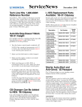
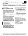
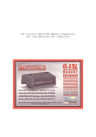
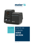
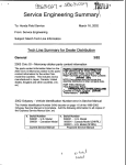
2 ServiceNews March 2002 Front Suspension Squeaks in Cold Weather New Software for PGM Tester: SN211 On ’96–98 TLs, ’97–98 CLs, and ’96–98 3.5RLs, stiff lower arm ball joints in the front suspension can squeak in cold weather. To stop the squeaking, you need to exercise the ball joint. Here’s how: The latest PGM Tester software version SN211 (1/21/02) was sent to your service manager on the February ACURALINK CD. To load the software into the PGM Tester, use your 8MB program card and the normal updating procedure. For info about updating on the Interactive Network or on the DCS workstation, or for general CD questions, call the ACURALINK Support Center at 800-245-4343. For info on vehicle systems or using the PGM Tester, call Special Tools at 800-346-6327. For warranty policy inquiries, call Warranty at 310-783-3240. 1. Pop the front suspension lower arm ball joint loose from the lower arm (see section 18 in the appropriate S/M for details). 2. Move the tapered ball joint pin left and right and back and forth as far as you can, 10 times in each direction. 3. Move the tapered ball joint pin to the limit of its stroke, then push it around the joint 10 times in a circular direction. 4. Reinstall the lower arm onto the ball joint. 5. Repeat this procedure for the other side. LEFT AND RIGHT, AND LEFT AND RIGHT... GREAT ! NOW, CIRCULAR MOTION, SET OF TEN ! REMEMBER, GOOD FORM EVERYONE ! AND FEEL THE BURN ! ! Here’s some important info on SN211: • The new EVAP system function test has been expanded. It now covers ’98–99 2.3CLs, ’99–02 3.2TLs, ’01–02 3.2CLs, and ’02 RSXs. More vehicles will be added in future software releases. See S/B 02-005, EVAP System Function Testing and Diagnostics With the PGM Tester, found under Fuel and Emissions, for details. • Fuel tank pressure sensor (FTPS) has been added where it was missing from the EVAP system single and multiple solenoid function test. Owner’s Manual Fix: ’02 MDX Oil Specs Owner’s Manual: The oil specification on pages 261, 262, and the rear cover page are wrong. The correct oil for the ’02 MDX is 5W-30 not 5W-20. The chart on page 262 should look like this: • On ’99–02 3.2TLs, ’01–02 3.2CLs, and ’01–02 MDXs, don’t use the PGM Tester idle adjustment feature; it can cause an idle fluctuation that resembles a faulty intake air control (IAC) valve. This problem will be fixed in the next software release. • Automatic Transmission snapshots cannot be transmitted to Tech Line by the Data Transfer Module (DTM). Special tools is working on fixing this bug. WRONG ’02 RSX: Can’t Turn Off the A/C While in Defrost Am bient Tem perat ure CORRECT Am bient Tem perat ure For a complete and accurate oil recommendation chart, see the January ’02 issue of S/N. The ’02 RSX has new heater control panel logic that prevents the user from turning the A/C compressor off when in the defrost mode. The logic for the RSX is very similar to the logic used in the 3.2TL, the 3.2CL, the RL and the MDX. When defrost is selected, the A/C compressor turns on and fresh air is directed towards the windshield. The defrost mode is set up this way to help improve defrosting performance. Troubleshooting Multiple Misfire DTCs Power Seat Won’t Move: ’01–02 MDX Touring NOTE: This article applies to ’99–03 3.2TLs, ’01–03 3.2CLs, and ’01–02 MDXs. If you have a driver’s or passenger’s seat on an MDX Touring model that isn’t working, the harness may have been misrouted after someone worked near it. Make sure this harness is routed above the front boss on the side seat trim. Do not route the harness below the side seat trim mounting boss, or the harness may become pinched or chafed, and cause a short which can blow the No. 2, No. 3, No. 4, or No. 5 fuse in the passenger’s under-dash fuse/relay box. If the harness is damaged, replace the harness. When troubleshooting misfire DTCs (P0301 thru P0306) with the PGM Tester, look at the freeze data values for the throttle position (TP) sensor and the exhaust gas recirculation valve lift sensor (EGR VLS). If the EGR VLS value is more than 1.25 volts and the TP sensor value is 0.5 volt (closed throttle), the EGR valve opened when it should have been closed, and it is defective. Replace the EGR valve. If the TP sensor value is more than 0.5 volt and the vehicle speed sensor (VSS) and RPM values indicate that the DTC was set while the vehicle was moving, write down or print out the EGR VLS value. Then, drive the vehicle at the same VSS and RPM values as shown in the freeze data, and note the EGR VLS value: FRONT BOSS Route the power seat harness over the top of the front boss. • If the freeze data EGR VLS value is more than 1.25 volts but the EGR VLS value from the test drive is less than 1.25 volts, the EGR valve was stuck open, and it is defective. Replace the EGR valve. • If the EGR VLS value from the test drive is similar to the EGR VLS value on the freeze data, the EGR valve is OK and isn’t the cause of your misfire DTCs. Look for other possible causes. S/M Fix: ’01–02 MDX Oil Specs The oil specifications on page 3-2 of the 2001–02 MDX Service Manual are wrong. Correct them like this: WRONG Am bient Tem perat ure CORRECT Am bient Tem perat ure For a complete and accurate oil recommendation chart, see to the January ’02 issue of S/N. POWER SEAT SWITCH Troubleshooting Multiple Indicators: All Models ABS/TCS and VSA control units communicate with the ECM/PCM. If a DTC causes a loss of communication among these control units, the loss can cause multiple indicators to come on. For instance, when the ABS/TCS control unit stops getting data from the ECM/PCM, it sets a DTC such as TCS DTC 31 [engine retard command (PFINH) signal]. This DTC doesn’t mean there’s a circuit or control unit failure; it means the flow of data has stopped. If you troubleshoot the PGM-FI system or the ABS/TCS first and clear the DTCs, you’ll most likely fix the problem. As a general rule, troubleshoot DTCs that aren’t related to communication first. For example, if DTC P1676 (FPTDR signal line failure) is set, and the ABS/TCS control unit sets a TCS DTC 24 thru 27 (TCS solenoid), troubleshoot the TCS DTC problem first. A second example: If the ECM/PCM sets DTC P1498 (EGR valve position sensor circuit voltage high), and the ABS/TCS control unit sets TCS DTC 31 [engine retard command (PFINH) signal], troubleshoot DTC P1498 first. DTC P0171 and DTC P0172 Troubleshooting Tips DTC P0171 (fuel system too lean) and DTC P0172 (fuel system too rich) can set when the ECM/PCM makes adjustments to the fuel mixture that are out of range in relation to the input from the heated oxygen sensor (HO2S). Some Acura vehicles use a universal exhaust gas oxygen (UEGO) sensor. You’ll see the values for this sensor listed as Air/Fuel Feedback (AF FB) on the PGM Tester display screen. Here’s a handy table to help you diagnose and repair DTC P0171 and DTC P0172 problems. Parameter Expected Values Long-Term Fuel Trim (LT FT) or Air/Fuel Feedback Average (AF FB AVG) LT FT or AF FB AVG normally reads 1.00 on the PGM Tester. When the LT FT or AF FB AVG values reach .85 (rich) or 1.15 (lean), the MIL comes on and the appropriate DTC sets. Short-Term Fuel Trim (ST FT) or Air/Fuel Feedback (AF FB) ST FT or AF FB normally fluctuates around 1.00 and should not hold a high or low value. If the ST FT value is high or low, find the driving condition, using freeze data, that causes the ST FT to peak. Engine Coolant Temperature (ECT) 0.5 to 0.7 V (engine at normal operating temperature) Intake Air Temperature (IAT)* 1.0 to 2.0 V (engine at normal operating temperature) Throttle Position (TP) Sensor 0.5 (closed throttle) to 4.5 V (wide-open throttle) Barometric Pressure (BARO)** 2.8 to 2.9 V at sea level; 2.5 V at 5,000 feet Manifold Absolute Pressure (MAP)** 0.8 to 1.0 V at idle, no load Exhaust Gas Recirculation Valve Lift Sensor (EGR VLS) 1.1 to 1.25 V at idle Manifold Vacuum The manifold vacuum should be 20 inches, or the equivalent MAP sensor voltage should be less than 1.0 V, when idling at sea level, no load. If the MAP sensor voltage is higher than 1.0 V, the engine has low manifold vacuum that will cause a rich mixture. Some causes for low manifold vacuum are tight or leaking valves, incorrect camshaft timing, low compression, or an EGR valve that’s stuck open. Fuel Pressure On models with vacuum-operated fuel pressure regulators, make sure you measure fuel pressure with the pressure regulator vacuum hose connected and disconnected. Refer to the appropriate S/M for fuel pressure specifications. Fuel Injectors Connect the fuel pressure gauge, and start the engine. Turn off the engine, slowly and carefully pinch the return hose, and check the fuel pressure leak down rate. If the fuel pressure decreases by more than 10 psi in 30 minutes, an injector is leaking and causing a rich mixture. Debris in the injector screens can cause DTC P0171 or P0172. If you find debris, replace the injectors, but find the source of contamination before installing the new injectors. * ECT and IAT sensor voltage should be the same when the engine is cold. ** MAP and BARO sensor voltage should be the same with the ignition switch turned on and the engine off. Measure Voltage Drops to Pinpoint Problems Measuring for voltage drops is one of the best ways to find unwanted resistance (bad ground, connector, connection, etc.) in a circuit or component. It’s a really easy and quick procedure, and you can use it on both the ground and power sides of the circuit. The tests are done with normal system voltage going through the circuit. While checking for continuity with an ohmmeter lets you find simple opens and shorts easily, measuring for voltage drops points you right to those elusive poor connections and bad switch or solenoid contacts that waste your time. A voltage drop in either the power side or ground side of a circuit means the component isn’t getting all the current it’s supposed to from that circuit. So, it isn’t going to work the way it should, or it may not even work at all. An engine that won’t crank fast enough because of corroded battery connections is a classic example of a voltage drop. To help you understand voltage drop, let’s take a quick look at Ohm’s Law: E = I x R. Since E is voltage, I is current, and R is resistance, another way to express this equation is Voltage = Current x Resistance. Therefore, when you have current flowing through a circuit with resistance, you’ll have a voltage drop. To illustrate the voltage drop principle, let’s troubleshoot a light that’s dimmer than normal. First, we’ll check the power side of the circuit. Connect the positive lead of your digital voltmeter* to the side of the switch that’s nearest the power source. Then connect the negative lead to the side of the switch that’s nearest the light. Now turn on the light. NOTE: You can’t check for a voltage drop unless the circuit is “on” (remember, there has to be current flow). Even if the component in the circuit won’t work at all, turn it on. Let’s say your voltmeter reads 4.0 V. This means there’s a voltage drop of 4.0 V in the switch. The light’s dim because it’s only getting 8.0 V instead of 12.0 V. That means there’s a bad connection or dirty contacts (resistance) inside the switch. On the other hand, let’s suppose there isn’t enough voltage drop in the power side of the circuit to cause a problem (less than 1.0 V, probably only 0.1 to 0.2 V). So now we’ll check the ground side of the circuit. Connect the positive lead of your voltmeter to the ground side of the light and the negative lead to a good body ground. Look at your voltmeter; if it’s reading 3.0 V, you’ve found the bad connection (resistance) that’s causing the light to dim. While most of the circuits you troubleshoot are probably not this simple, the principle remains are the same. Remember these tips when measuring voltage drops: • Find out if the voltage drop is on the power side or on the ground side. • Measure for voltage drop from the power source to the component, then from the component to ground. • Pinpoint the exact location of the problem by referring to the appropriate ETM, and measuring the voltage drop in each length of wire, across each connector, each fuse, each splice, and each switch in that circuit. * Make sure you use a digital voltmeter. Since a voltage drop of less than 1.0 V is enough to cause a problem, an analog voltmeter isn’t sensitive enough. 2 ServiceNews 2002 American Honda Motor Co., Inc. - All Rights Reserved. Published by AHM Service Communications, 1919 Torrance Blvd., Torrance, CA 90501-2746. All suggestions become the property of American Honda Motor Co., Inc.; sending a suggestion gives Honda permission to publish it without further consideration. BSN 23737 (0203)