1
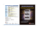
72-6855 & 72-6856
BENCH POWER SUPPLIES
INSTRUCTION MANUAL
Tenma 72-6855 & 72-6856 Instruction manual
Table of Contents
Introduction
2
Specification
2
Safety
4
Installation
5
Connections
5
Operation - Main Outputs
6
Operation - Auxiliary Output
7
Operation - General
7
Maintenance
8
www.tenma.com
1
Introduction
The 72-6855 and 72-6856 provide high levels of power (up to 305 watts) in a compact and
attractive case style.
High resolution controls allow precise setting of voltage and current levels which are indicated on
accurate and legible digital meters.
Excellent line and load regulation are matched by low noise and good transient response. High
power efficiency ensures that the unit remains cool without any fan noise. Remote sense
terminals are provided so that good regulation can be maintained across remote loads at high
current.
The 72-6855 has two independent and isolated outputs each with a 0 to 35V, 0 to 4A capability.
The outputs operate in constant voltage or constant current mode with automatic cross-over and
mode indication. Each output has its own on-off switch. Where higher voltages or currents are
required the outputs can be wired in either series or parallel to provide voltages up to 70 volts or
currents up to 8 Amps.
The 72-6856 has, in addition, an Auxiliary ‘logic voltage’ output with a 5A current capability. To
reflect the increasing usage of low-voltage logic devices, this output can be preset between
1.5 volts and 5 volts via a front panel control.
The total power capability is 280 watts for the dual supply and 305 watts for the triple.
The 72-6855 and 72-6856 incorporates separate digital voltage and current meters on each main
output. The meters use bright 14mm (0·56”) LED displays and have an update rate of 4 per
second providing near instantaneous response. Simultaneous metering of voltage and current
provides accurate information “at a glance” and avoids any possibility of misinterpretation. When
an output switch is set to “off”, the current limit setting is displayed enabling conditions to be set
before the load is connected. With the right-hand main output off, the right-hand meters can be
used to momentarily display the preset Auxiliary voltage and current limit.
The 72-6855 and 72-6856 have been designed to meet the stringent requirements of relevant
IEC standards for safety and EMC, including harmonics emissions. All outputs are intrinsically
short circuit proof, and are protected against external voltages and reverse currents.
Specification
MAIN OUTPUTS
2
Voltage Range:
0V to 35V minimum.
Current Range:
0A to 4A minimum.
Output Voltage Setting:
By coarse and fine controls.
Output Current Setting:
By single logarithmic control.
Operating Mode:
Constant voltage or constant current with automatic cross-over.
Output Switch:
Electronic. Preset voltage and current displayed when off.
Output Terminals:
Universal 4mm safety binding posts on 19mm (0.75”) pitch.
Sensing:
Switchable between local and remote. Spring-loaded push
terminals for remote connection.
Output Protection:
Output will withstand up to 40V forward voltage.
Reverse protection by diode clamp for reverse currents up to 3A.
Load Regulation:
<0.01% of maximum output for 90% load change, using remote
sense.
Line Regulation:
<0.01% of maximum output for 10% line change.
Tenma 72-6855 & 72-6856 Instruction manual
Ripple & Noise
(20MHz bandwidth):
Typically <2mVrms, <10mVpk-pk, constant voltage mode.
Transient Response:
<200µs to within 50mV of set level for a 5% to 95% load change.
Temperature Coefficient:
Typically <100ppm/°C.
Status Indication:
Output on lamp. Constant current mode lamp.
METER SPECIFICATIONS (Main Outputs)
Meter Types:
Dual 4 digit meters with 14mm (0·56") LEDs. Reading rate 4 Hz.
Meter Resolutions:
10mV, 1mA.
Meter Accuracies:
Voltage 0.3% of reading ± 3 digits,
Current 0.5% of reading ± 3 digits.
AUXILIARY LOGIC OUTPUT (72-6855 only)
Voltage:
Variable <1.5V to >5V by front panel control.
Meter Voltage Accuracy:
0.3% ± 4 digits
Current Limit:
5A minimum.
Output Protection:
Output will withstand up to 7V forward voltage.
Diode clamp reverse protection for currents up to 3A.
Load Regulation:
<0.5% for 90% load change.
Line Regulation:
<0.1% for 10% line voltage change.
Ripple & Noise
(20MHz bandwidth):
Typically <2mVrms, <10mVpk-pk, constant voltage mode.
Transient Response:
Typically <200µs to within 50mV of set level for a 5% to 95% load
change.
Temperature Coefficient:
Typically <100ppm/ºC.
Status Indication:
UNREG lamp.
GENERAL
AC Input:
110V - 240V AC ± 10%, 50/60Hz. Installation Category II.
Power Consumption:
500VA max.
Operating Range:
+5ºC to +40ºC, 20% to 80% RH.
Storage Range:
−40ºC to + 70ºC.
Environmental:
Indoor use at altitudes up to 2000m, Pollution Degree 2.
Safety:
Complies with EN61010-1.
EMC:
Complies with EN61326.
Size:
260 x 160 x 320mm (WxHxD).
Weight:
4.3kg
www.tenma.com
3
Safety
This power supply is a Safety Class I instrument according to IEC classification and has been
designed to meet the requirements of EN61010-1 (Safety Requirements for Electrical Equipment
for Measurement, Control and Laboratory Use). It is an Installation Category II instrument
intended for operation from a normal single phase supply.
This instrument has been tested in accordance with EN61010-1 and has been supplied in a safe
condition. This instruction manual contains some information and warnings which have to be
followed by the user to ensure safe operation and to retain the instrument in a safe condition.
This instrument has been designed for indoor use in a Pollution Degree 2 environment in the
temperature range 5°C to 40°C, 20% - 80% RH (non-condensing). It may occasionally be
subjected to temperatures between +5°C and –10°C without degradation of its safety. Do not
operate while condensation is present.
Use of this instrument in a manner not specified by these instructions may impair the safety
protection provided. Do not operate the instrument outside its rated supply voltages or
environmental range.
WARNING! THIS INSTRUMENT MUST BE EARTHED
Any interruption of the mains earth conductor inside or outside the instrument will make the
instrument dangerous. Intentional interruption is prohibited. The protective action must not be
negated by the use of an extension cord without a protective conductor.
When the instrument is connected to its supply, terminals may be live and opening the covers or
removal of parts (except those to which access can be gained by hand) is likely to expose live
parts. The apparatus shall be disconnected from all voltage sources before it is opened for any
adjustment, replacement, maintenance or repair. Capacitors inside the power supply may still be
charged even if the power supply has been disconnected from all voltage sources but will be
safely discharged about 10 minutes after switching off power.
Any adjustment, maintenance and repair of the opened instrument under voltage shall be avoided
as far as possible and, if inevitable, shall be carried out only by a skilled person who is aware of
the hazard involved.
If the instrument is clearly defective, has been subject to mechanical damage, excessive moisture
or chemical corrosion the safety protection may be impaired and the apparatus should be
withdrawn from use and returned for checking and repair.
Make sure that only fuses with the required rated current and of the specified type are used for
replacement. The use of makeshift fuses and the short-circuiting of fuse holders is prohibited.
Do not wet the instrument when cleaning it.
The following symbols are used on the instrument and in this manual:Earth (ground) terminal.
mains supply OFF.
l
mains supply ON.
alternating current (ac)
direct current (dc)
4
Tenma 72-6855 & 72-6856 Instruction manual
Installation
Mains Operating Voltage
This instrument has a universal input range and will operate from a nominal 115V or 230V mains
supply without adjustment. Check that the local supply meets the AC Input requirement given in
the Specification.
Mains Lead
When a three core mains lead with bare ends is provided this should be connected as follows:
BROWN
-
MAINS LIVE
BLUE
-
MAINS NEUTRAL
GREEN/YELLOW
-
EARTH
Safety Earth Symbol
When fitting a fused plug a 5 amp fuse should be fitted inside the plug. As the colours of the
wires in the mains lead of this apparatus may not correspond with the coloured markings
identifying the terminals in your plug proceed as follows:
The wire which is coloured green-and-yellow must be connected to the terminal in the plug which
is marked by the letter E or by the safety earth symbol shown above or coloured green or greenand-yellow.
The wire which is coloured blue must be connected to the terminal which is marked with the letter
N or coloured black.
The wire which is coloured brown must be connected to the terminal which is marked with the
letter L or coloured red.
WARNING! THIS INSTRUMENT MUST BE EARTHED.
Any interruption of the mains earth conductor inside or outside the instrument will make the
instrument dangerous. Intentional interruption is prohibited.
Connections
All connections are made from the front panel.
The load should be connected to the positive (red) and negative (black) terminals marked
OUTPUT.
Remote sense connections to the load, if required, are made from the positive (+) and
negative (−) SENSE terminals. Switch the LOCAL/REMOTE switch to REMOTE when remote
sensing is required. Switch back to LOCAL when remote sensing is not in use.
The terminal marked
is connected to the chassis and safety earth ground.
www.tenma.com
5
Operation - Main Outputs
The operation of both main outputs is identical; the following description applies to both.
Switching On
The POWER switch is located at the bottom left of the front panel. When the POWER switch is
turned on ( l ) the right hand meter briefly indicates the firmware revision before the display
shows Volts and Amps.
Setting Up the Output
With the POWER switch on (l) and the
output OFF the output voltage and current limit can
be accurately preset using the VOLTAGE and CURRENT controls; the left-hand meter shows the
set voltage and the right-hand meter shows the set maximum current.
When the output switch is switched ON, the
lamp lights; the left-hand meter now shows the
actual voltage and the right-hand meter the actual load current.
Constant Voltage
The output voltage is adjusted using the coarse and fine VOLTAGE controls; the CURRENT
control sets the maximum current that can be supplied.
Constant Current
If the load resistance is low enough such that, at the output voltage set, a current greater than the
current limit setting would flow, the power supply will automatically move into constant current
operation. The current output is adjusted by the CURRENT control and the VOLTAGE controls
set the maximum voltage that can be generated.
The CC lamp lights to show constant current mode.
Instantaneous Current Output
The current limit control can be set to limit the continuous output current to levels down to 10mA.
However, in common with all precision bench power supplies, a capacitor is connected across the
output to maintain stability and good transient response. This capacitor charges to the output
voltage and short-circuiting of the output will produce a current pulse as the capacitor discharges
which is independent of the current limit setting.
Protection
The output has intrinsic short-circuit protection and is protected from reverse voltages by a diode;
the continuous reverse current must not exceed 3 Amps, although transients can be much higher.
The output is protected against externally applied forward voltages of up to 40V.
Remote Sensing
The unit has a very low output impedance, but this is inevitably increased by the resistance of the
connecting leads. At high currents this can result in significant differences between the indicated
source voltage and the actual load voltage (two 20mΩ connecting leads will drop 0.2V at 5 Amps,
for instance). This problem can be minimised by using short, thick, connecting leads, but where
necessary it can be completely overcome by using the remote sense facility.
This requires the sense terminals to be connected to the output at the load instead of at the
source; insert wires into the spring-loaded SENSE terminals and connect directly to the load.
Switch the LOCAL/REMOTE switch to REMOTE. To avoid instability and transient response
problems, care must be taken to ensure good coupling between each output and sense lead. This
can be done either by twisting the leads together or by using coaxially screened cable (sense
through the inner). An electrolytic capacitor directly across the load connection point may also be
beneficial.
The voltage drop in each output lead must not exceed 0.5 Volts.
Switch the LOCAL/REMOTE switch back to LOCAL when remote sensing is not in use.
6
Tenma 72-6855 & 72-6856 Instruction manual
Operation - Auxiliary Output
Output Voltage
The output voltage can be set between 1.5V and 5.0V using the front panel rotary adjustment
beside the centre terminals. With the right-hand main output OFF, pressing the SHOW AUX
PRESET button will display the AUX output voltage and current limit on the right-hand meters.
Current Limit
The output will go into current limit at between 5A and 6A; the UNREG lamp lights in this
condition.
Protection
The output has intrinsic short-circuit protection and is protected from reverse voltages by a diode;
the continuous reverse current must not exceed 3 Amps, although transients can be much higher.
The output is protected against externally applied forward voltages of up to 7V.
Operation - General
Connection to the Load
The load should be connected to the positive (red) and negative (black) output terminals. Both
are fully floating and either can be connected to ground.
Series or Parallel Connection with Other Outputs
The outputs of the power supply are fully floating and may be used in series with other power
supply units to generate high DC voltages up to 300V DC.
The maximum permissible voltage between any terminal and earth ground ( ) is 300VDC; the
maximum permissible voltage between either terminal of one output and any terminal of another
output on the same supply is also 300VDC.
WARNING! Such voltages are exceedingly hazardous and great care should be taken to shield
the output terminals for such use. On no account should the output terminals be touched when
the unit is switched on under such use. All connections to the terminals must be made with the
power switched off on all units.
It should be noted that the unit can only source current and cannot sink it, thus units cannot be
series connected in anti-phase.
The unit can be connected in parallel with others to produce higher currents. Where several units
are connected in parallel, the output voltage will be equal to that of the unit with the highest output
voltage setting until the current drawn exceeds its current limit setting, upon which the output will
fall to that of the next highest setting, and so on. In constant current mode, units can be
connected in parallel to provide a current equal to the sum of the current limit settings.
Ventilation
The power supply is very efficient but nevertheless can generate significant heat at full power.
The supply relies on convection cooling only and it is therefore important that ventilation is never
restricted if performance and safety are to be maintained.
www.tenma.com
7
Maintenance
The Manufacturers or their agents overseas will provide repair for any unit developing a fault.
Where owner wish to undertake their own maintenance work, this should only be done by skilled
personnel in conjunction with the service manual which may be purchased directly from the
Manufacturers or their agents overseas.
Fuse
The correct fuse type is:
10 Amp 250V HBC time-lag(T), 5 x 20mm.
Note that the main function of the fuse is to make the instrument safe and limit damage in the
event of failure of one of the switching devices. If a fuse fails it is therefore very likely that the
replacement will also blow, because the supply has developed a fault; in such circumstances the
instrument will need to be returned to the manufacturer for service.
Make sure that only fuses of the required rated current and specified type are used for
replacement. The use of makeshift fuses and the short-circuiting of fuse-holders is prohibited.
To replace a fuse, first disconnect the instrument from the AC supply. Remove the 7 cover
securing screws and lift off the cover. Replace the fuse with one of the correct type and refit the
cover.
Cleaning
If the PSU requires cleaning use a cloth that is only lightly dampened with water or a mild
detergent. Polish the display window with a soft dry cloth.
WARNING! TO AVOID ELECTRIC SHOCK, OR DAMAGE TO THE PSU, NEVER ALLOW
WATER TO GET INSIDE THE CASE. TO AVOID DAMAGE TO THE CASE OR DISPLAY
WINDOW NEVER CLEAN WITH SOLVENTS.
8
TEST EQUIPMENT
405 Pioneer Blvd.
Springboro, Ohio 45066
Book Part No. 48511-1390 Issue 1