1
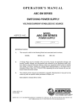
TECHNICAL MANUAL UNIVERSAL BOP GPIB VISA INSTRUMENT DRIVER MODEL KEPCO INC. An ISO 9001 Company. UNIVERSAL BOP GPIB VISA INSTRUMENT DRIVER ORDER NO. REV. NO. IMPORTANT NOTES: 1) This manual is valid for the following Model and associated serial numbers: MODEL SERIAL NO. REV. NO. 2) A Change Page may be included at the end of the manual. All applicable changes and revision number changes are documented with reference to the equipment serial numbers. Before using this Instruction Manual, check your equipment serial number to identify your model. If in doubt, contact your nearest Kepco Representative, or the Kepco Documentation Office in New York, (718) 461-7000, requesting the correct revision for your particular model and serial number. 3) The contents of this manual are protected by copyright. Reproduction of any part can be made only with the specific written permission of Kepco, Inc. Data subject to change without notice. KEPCO® ©2014, KEPCO, INC P/N 243-1098-r1 THE POWER SUPPLIER™ KEPCO, INC. 131-38 SANFORD AVENUE FLUSHING, NY. 11355 U.S.A. TEL (718) 461-7000 FAX (718) 767-1102 email: [email protected] World Wide Web: http://www.kepcopower.com UNIVERSAL BOP GPIB VISA INSTRUMENT DRIVER The VISA instrument driver supplied with BOP Series Power Supplies is provided to simplify programming with a VISA compatible GPIB controller. The latest driver can be downloaded from the Kepco website (http://www.kepcopower.com/drivers.htm). Included in the driver are: • source code (C) for all VISA functions (kp_BOP.c) • a complete programming reference manual (kp_BOP.pdf) • a sample application of the VISA functions (written in C) which can be used to program one or more BOP power supplies using a virtual front panel observed on a computer monitor (bit.4886.exe). 1. DEMONSTRATION PROGRAM USING THE VISA DRIVER The demonstration program is intended to illustrate the use of the VISA functions included with the BOP power supply. The demonstration program is installed under Windows by running SETUP.EXE. The program can be used to program and view the virtual front panels of up to 10 BOP Power Supplies. After the program is installed, double click on BOP.exe to run the program. 1. Unzip the files and doubleclick on setup.exe to install the driver. The bit_mdac folder will be added to the Start - Programs folder. Doubleclick bit_mdac.exe to run the program, and refer to the visamdac.pdf in the bit_mdac folder for details about using the soft front panel. 2. Install the VISA driver per the text file included with the driver. At the Start-up screen (Figure 1) set the correct GPIB Address and click CONNECT. When the Power Supply Type window shows BIT 4886, click Continue. FIGURE 1. BOP-VISA 042114 GPIB VISA DRIVER START-UP 3 Once you are connected to the VISA interface, the virtual front panel appears (see Main Panel, Figure 2). FIGURE 2. MAIN PANEL 1.1 MAIN PANEL BUTTONS The main panel shows all power supply parameters simultaneously, without having to execute local controls and read the corresponding display. The main panel is a real-time display of output values and programmed parameters. All functions are available from the main panel. The title bar at the top of the window (not shown) indicates the BOP model connected to the GPIB interface. NOTE: Some buttons may disabled for special BOP models or those using special BIT cards (special models include a 5-digit suffix). The Mode button changes the operating mode (CV or CC); Mode indicators light to indicate whether the power supply is operating in either CV (constant voltage) or CC (constant current) mode. The analog meters read actual output voltage and current; Two Display windows at the center provides a more precise digital readout of actual output voltage and current. The Range button opens a dropdown box; to change the operating range: either High, Low or Auto range must be selected. The Output button applies the programmed settings to the output terminals (ON) or keeps the output voltage and current at zero (OFF). The Gain button (not shown - available only with BOP’s of 1000W and above or with MDAC BIT card) opens a dropdown box which allows the selection of the reference voltage: INT for Internal or EXT1 or EXT2 for one of two external analog reference voltages used to calibrate the gain. Indicators on either side of the digital display window, V limit and C limit, light (yellow) if the programmed voltage or current limit is exceeded and light (red) if a protection error is detected Set Voltage and Set Current windows are used to program the output voltage and current for the unit; settings can be changed either by clicking on the arrows to the left of the display window, or by using the mouse to highlight the setting, then typing in the new value. 4 BOP-VISA 042114 The BEEP button causes the power supply to beep. The ABOUT button displays the model, serial number and firmware version number. The Trans button (not available with BIT 4882 card) generates a transient pulse with the amplitude and duration specified by the user in the Transient Pulse window (see Figure 3). The output level of the transient will either be V or A, depending on which mode is active. After the transient pulse is generated, the output will return to the programmed values in effect before the transient was generated. FIGURE 3. TRANSIENT PULSE WINDOW The Trigger button opens the Trigger window (Figure 4) which allows 99 different trigger voltage and current values, as well as mode to be stored and recalled. The STORE button stores the Trigger Mode, Trigger Voltage and Trigger Current values at the selected Memory location (1-99). The Recall button displays the Trigger Mode, Trigger Voltage and Trigger Current values stored in the selected Memory location. Clicking the Trigger button (or double-clicking RECALL) within the Trigger window causes the power supply output to be programmed to the settings stored in the selected Memory location. . FIGURE 4. TRIGGER WINDOW The Calibrate button opens the Calibration Window (Figure 5), and is used to recalibrate the unit (see Section 3 of the Operator’s Manual or Section 4 of the Service Manual). FIGURE 5. BOP-VISA 042114 CALIBRATION WINDOW 5 The Utilities button opens the Utilities window (Figure 6). The Hardware Test button tests the validity of system parameters (e.g., CRC). FIGURE 6. UTILITIES WINDOW The Power Test button performs a full power test by first testing maximum voltage output, then testing minimum voltage output. Model Configuration. Special models of BOP power supplies and BIT interface cards are identified by a 5-digit suffix. A text file supplied with the driver, optionxxxxx.txt (where xxxxx = the 5-digit suffix) identifies how the special unit has been configured using the control commands described in the Theory of Operation section of the applicable technical manual. When the 5-digit number is entered in the Model Configuration TEST NUMBER window, and the TEST button is pressed, the optionxxxxx.txt file is scanned and the configuration is verified, resulting in either PASSED or TEST FAILS displayed in the TEST NUMBER window. NOTE: The TEST button must also be used to reconfigure special shutdown requirements each time the VISA application is started. Entering the 5-digit suffix in the Model Configuration UPDATE TEST window and clicking the UPDATE button, restores the factory set special options using the optionxxxxx.txt file. When directed by factory support, this feature can be used to change the configuration of the unit to accommodate customer requests or firmware upgrades. The Reset button on the Main Panel (Figure 2) resets the unit to the power up defaults: output voltage and current set to zero, and output off. The QUIT button on the virtual panel (Figure 2) is used to exit the sample VISA application. 2. PROGRAMMER REFERENCE 2.1 VISA INSTRUMENT DRIVER FUNCTIONS Kepco’s BOP VISA instrument driver provides programming support for Kepco’s BOP Power Supply (VISA I/O). It contains functions for opening, configuring, taking measurements from, test, calibration and closing the instrument. To successfully use this module, the instrument must be connected to the GPIB and the GPIB address supplied to the initialize function must match the GPIB address of the instrument. 6 BOP-VISA 042114 Table 1 lists the functions that are available. TABLE 1. BOP VISA DRIVER FUNCTIONS Purpose Function Name Description INITIALIZE FUNCTION Initialize KpBop_init Initializes the instrument and sets it to a default configuration. APPLICATION FUNCTIONS — This class of functions contains high-level test and measurement routines. These functions call other instrument driver functions to configure, start, and get readings from the instrument. Set and Measure KpBop_ApplicSetMeas Used to either set and read back, or just read back the output voltage, current and operating mode of the power supply CONFIGURATION FUNCTIONS — This class of functions configures the instrument by setting system configuration parameters. Get Current Range Status Kpbop_getCurrRange Unit can operate in either auto, high or low range. The function will return 0 for auto, 1 for high range and 4 for low range Set Current Range Kpbop_setCurrRange Sets the current operating range (auto, high or low) Get Voltage Range Status Kpbop_getVoltRange Unit can operate in either auto, high or low range. The function will return 0 for auto, 1 for high range and 4 for low range Set Voltage Range Kpbop_setVoltRange Sets the voltage operating range (auto, high or low) Get Minimum or Maximum Value KpBop_GetMinMaxValue Gets the minimum or the maximum output voltage, output current of the power supply depending on the min_max switch and slide selection position. Set Trigger Voltage and Current KpBop_SetTrig_Volt_Curr Sets the trigger voltage and trigger current at the same time Set Trigger Value KpBop_SetTrigValue Sets the trigger voltage or trigger current level, depending on the switch position. Get Trigger Value KpBop_GetTrigValue Gets the trigger voltage or the trigger current level, depending on the switch position. ACTION/STATUS FUNCTIONS — This class of functions executes commands and queries. It also provides functions which allow the user to determine the current status of the instrument. Set Voltage and Current KpBop_Set_Volt_Curr Sets the output voltage and current at the same time. Set Value KpBop_SetValue Sets the output voltage, the output current of the power supply, depending on the slide selection position. The values are checked against the maximum acceptable values for the corresponding power supply. Get Value KpBop_GetValue Gets the output voltage, the output current of the power supply depending on slide selection position. Transient pulse in voltage mode Kpbop_TransVolt Sets the power supply to the required value for the indicated time Transient pulse in current mode Kpbop_TransCurr Sets the power supply to the required value for the indicated time Clear List parameter Kpbop_ListClr Clears all the parameters of a list, set direction to UP and SEQ to Default (DSEQ) Count list parameter Kpbop_ListCount Sets the LIST seq to run for COUNT periods Dwell list parameter Kpbop_ListDwell Sets the time a list will run the current step (if entered for only location 0 will apply for all steps) Executes a list Kpbop_ListExec Starts the execution of a list, if all the parameters were correctly set. Defines list parameters (V or C) Kpbop_ListData Calculates the value (V or C, depending on which mode is active) for each of the STEPS of a list, in accordance with the waveform and the max and min values selected Trigger KpBop_Trig Triggers the instrument once. The output will go to the trigger voltage and current values. BOP-VISA 042114 7 TABLE 1. BOP VISA DRIVER FUNCTIONS (CONTINUED) Purpose Function Name Description Measure Current and Voltage Output Values Kpbop_MeasVoltCurr Measures the values of output (voltage and current). Measure Current and Voltage Output Values Kpbop_MsVoltCurr Measures the value of output voltage and then the value of output current. Measure Output Value KpBop_MeasValue Measures the value of output voltage or current depending on the switch position. Get Source Mode KpBop_GetSourceMode Gets the operating mode of the power supply. Set Gain Kpbop_SetGain Select reference voltage INT (internal) , EXT1 or EXT2 Set Source Mode Kpbop_SetSourceMode Set power supply mode: voltage or current depending on the switch position. Output On/Off KpBop_OutputOnOff Sets the output on or off. Get Output Status KpBop_getOutputState Returns the output status (on or off). Abort Measurement KpBop_abortMeas Sends the abort command. Beep KpBop_beep The selected BOP power supply will emit a beep. DATA FUNCTIONS — This class of functions transfers data to or from the instrument. Save/Recall Settings KpBop_SaveRecSet Saves the current settings to the selected memory location or restores previously stored settings from a memory location. The memory location range is from 1 to 40. UTILITY FUNCTIONS — This class of functions provides lower level functions to communicate with the instrument and to change instrument parameters. Identify Power Supply KpBop_identify Returns the full message returned by the power supply to the *IDN? query. This message contains four fields: manufacturer, power supply type, serial number and firmware version. Revision Query KpBop_RevisionQuery Returns the revision numbers of the instrument driver and instrument firmware version from the *idn? query. This instrument driver's Revision Number is "Rev 1.0, 9/99, CVI 5.1" and the BOP firmware version is Firmware Version "1.0". This data is necessary when requesting technical support. Model Query KpBop_ModelQuery Return the model number of the BOP power supply. Serial Number Query KpBop_SerialnQuery Returns the serial number of the BOP power supply. The serial number is extracted from the answer to the *idn? query. Query SCPI Version KpBop_GetScpiVersion Returns the power supply answer to the Query SCPI Version command. Checks the Standard Commands for Programmable Instruments (SCPI) language version. Write To Instrument KpBop_writeInstrData This function writes commands and queries to the instrument to modify parameters and query device settings. Read Instrument Data KpBop_readInstrData This function reads data from the instrument's output buffer and returns it to the specified variable in memory. Because the instrument may return both numeric and text data in response to queries, this function returns the data in string format. NOTE: If valid data is not available at the instrument's output buffer when this function is called, the instrument will hang up and the function will not return until it times out. If the time-out is disabled, this function will hang indefinitely and it may be necessary to reboot the computer to break out. Reset KpBop_psReset Resets the instrument to a known state and sends initialization commands to the instrument. Self-Test KpBop_selfTest Runs the instrument's self test routine and returns the test result(s). Error-Query KpBop_errorQuery Reads an error code from the instrument's error queue. Error Message KpBop_errorMessage Takes the Status Code returned by the instrument driver functions, interprets it and returns it as a user readable string. 8 BOP-VISA 042114 TABLE 1. BOP VISA DRIVER FUNCTIONS (CONTINUED) Purpose Function Name Description Calibration Status On/Off KpBop_CalStatus Used to enter or exit the calibration state. To enter the calibration state an 11-character password is required. When the instrument is shipped from the factory the calibration password is "DEFAULT". The password protects the instrument against unauthorized calibrations. Calibration Mode KpBop_CalMode Allows the user to select the calibration mode (either voltage or current calibration) and also allows selection of 0 (min) or full scale (max) calibration. Calibration Output KpBop_CalOutput Allows the user to perform the power supply calibration in both voltage or current mode. By moving the digital to analog converter the number of LSB's specified in the repeat count, the user can approach the 0 or full scale value of the corresponding power supply. This is a fine adjustment for the 0 or full scale value. The user can specify a repeat count between 1 and 9 in order to avoid having to repeat sending the command Calibration Zero KpBop_CalZero Used to zero the output of the power supply before switching from voltage calibration to current calibration (to allow a calibration resistor to be connected between the power supply output terminals. Zero Voltage Calibration Kpbop_CalVoltZero Calibrate output zero in Voltage mode. Zero Current Calibration Kpbop_CalCurrZero Calibrate output zero in Current mode. Volt_low Calibration constants Kpbop_CalVLSD Read Calibration constants when unit is in low-volt calibration mode. Volt Calibration constants Kpbop_CalVSND Read Calibration constants when unit is in voltage calibration mode. Curr_low Calibration constants Kpbop_CalCLSD Read Calibration constants when unit is in low-current calibration mode. Curr_high Calibration constants Kpbop_CalCSND Read Calibration constants when unit is in current calibration mode. Calibration Save KpBop_CalSave Stores the calibration results in the nonvolatile calibration memory of the instrument. Security Code KpBop_CalCode Allows the user to change the password to prevent accidental or unauthorized calibrations of the instrument. The password is stored in nonvolatile memory, and does not change when power has been off or after a reset. To change the password, the instrument must already be in calibration status, ensuring that the user knows the current password. If the password is lost, call the factory for support. Disable Password Kpbop_PassDis Allow user to disable the security code. Dump Calibration Kpbop_CalDUMP Save Calibration constants in files. Restore Calibration Kpbop_CalRestore Restore Calibration constants from files. Close KpBop_close This function takes the instrument off-line. BOP-VISA 042114 9 2.2 PROGRAM PRACTICES In addition to providing prototype functions listed in Table 1, the BOP_MDAC.H file, also provides enumerations for various Kepco-specific variables. The PS_TYPE enumeration defines the various Kepco BOP models supported by the driver and the associated INVALID TYPE. The CAL:MODE and CAL:STATe enumerations provide details for the calibration of various BOP/BIT combinations. 3. EXAMPLES The following examples show the functions needed to set voltage to 15V, current to 2 amp and output ON. Example 1: #INCLUDE “BOP_MDAC.N” ViByte ps_type; ViSession BOP_Session; /*add definition for driver prototype*/ Kpbop_init ("GPIB0::6", 1, &ps_type, &BOP_Session); Kpbop_Set_Volt_Curr (BOP_Session, 15, 2); Kpbop_OutputOnOff ( BOP_Session, KEPCO_ON); //init ps //voltage and current //output on Example 2: #INCLUDE “BOP_MDAC.N” ViByte ps_type; ViSession BOP_Session; /*add definition for driver prototype*/ Kpbop_init ("GPIB0::6", 1, &ps_type, &BOP_Session); //init ps Kpbop_SetValue (BOP_Session, KEPCO_VOLT, 15); //voltage Kpbop_SetValue (BOP_Session, KEPCO_CURRENT, 2);//current Kpbop_OutputOnOff ( BOP_Session, KEPCO_ON); //output on Delay (1); Kpbop-SetValue BOP_SESSION, KEPCO_VOLT, 25); //voltage now 25 volts Delay (1); Kpbop-SetValue BOP_SESSION, KEPCO_VOLT, 10); //voltage now 10 volts 10 BOP-VISA 042114