1
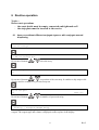
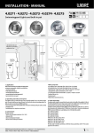
Instrument for the immunoblot processing
Dynablot
Operating and maintenance manual
Rev. 5
The knowledge imparted by this manual is required for the operation of the instrument.
Therefore please make yourself familiar with contents of this manual and pay particular
attention to notes on the safe operation of the instrument
Copyright
Copyright © Revised 2008 Dynex Technologies spol. s r.o..
All rights reserved. Reproduction of the accompanying user documentation in whole or in part
is prohibited.
Issued by :
DYNEX Technologies spol. s r.o.
Na Čihadle 32
160 00 Prague
Czech Republic
Rev.5
List of contents :
1
2
3
4
5
6
7
8
General instructions and safety .......................................................................................... 1
1.1 About this manual ........................................................................................................ 1
1.2 Symbols and markings................................................................................................. 1
1.3 Intended application .................................................................................................... 2
Instrument description ........................................................................................................ 2
Technical specifications ..................................................................................................... 3
Instrument transport, instalation and assembly .................................................................. 4
4.1 Instrument transport and unpacking ............................................................................ 4
4.2 Environmental requirements........................................................................................ 4
4.3 Instrument assembly .................................................................................................... 4
Instrument control description ........................................................................................... 5
5.1 Instrument switch on ................................................................................................... 5
5.2 Keyboard button description ....................................................................................... 5
5.3 Signal lights function ................................................................................................... 6
5.4 Main menu structure .................................................................................................... 6
5.5 Menu Pause structure................................................................................................... 7
Routine operation ............................................................................................................... 8
6.1 Assay run without different conjugate types or with conjugate manual dispensing ... 8
6.2 Assay run with different conjugate types, strips order according to methods ........... 11
6.3 Assay run with different conjugate types, strips order according to samples ........... 12
6.4 Pause .......................................................................................................................... 14
6.4.1
Stop of the strip plate carrier rocking ................................................................. 14
6.4.2
Pumps priming ................................................................................................... 14
6.4.3
Skip to another assay step or skip the incubation time ...................................... 14
6.5 Pumps priming........................................................................................................... 15
6.6 Pumps calibration ...................................................................................................... 16
6.7 Communication with PC ........................................................................................... 18
6.8 Power failure treatment ............................................................................................. 18
Maintenance ..................................................................................................................... 19
7.1 Tube and waste bottle purging................................................................................... 19
7.2 Instrument cleaning ................................................................................................... 19
7.3 Pumps ........................................................................................................................ 19
Troubleshooting ............................................................................................................... 20
8.1 Movements error........................................................................................................ 20
8.2 Control system fault................................................................................................... 21
i
Rev.5
ii
Rev.5
1 General instructions and safety
1.1
About this manual
The Operating and maintenance manual has been written for the user (e.g. laboratory
technician) and provides information on the Dynablot instrument. This manual contains the
instalation, operating and maintenance instruction for the Dynablot instrument.
Read the manual in its entirely prior to operating the instrument. The manual must be
kept near the instrument and user must have access to it at any time.
The Operating and maintenance manual refers to Dynablot Service manual which contains
description of service procedures.
1.2 Symbols and markings
These symbols are intended to draw your attention to essential information and alert you to
the presence of hazards as indicated.
I
Power ON
0
Power OFF
Caution: biohazard risk
Caution : risk of personal injury to the operator or a safety hazard to the
surrounding area
Producer
Date of production
1
Rev.5
1.3
Intended application
Dynablot is the strips washing and incubation device for processing biological samples
according to specifications described in this manual.
For in Vitro Diagnostic only!
Prior to the use of the Dynablot for IVD, any test methods (assays) or kiks must be validated
by the user in combination with the system according to common clinical laboratory practice,
local legislations and state of the art.
The device must only be operated by the laboratory personnel who have been trained on the
use of the instrument.
The instrument must only be used in accordance with its intended use.
2 Instrument description
Dynablot is the compact desktop instrument for the automatic processing of immunoblot
assays. Its capability is up to 44 strips in one run. Reagents are dispensed by 6 peristaltic
pumps during assays. Strip contents are aspirated to the waste bottle by the vacuum principle
way. Strip contents mixing during the incubation is done by rocking of the strips plate.
The instrument top part can be comfortably folded to make good access to the inner
instrument area. It enables comfortable handling during tubing replacement or possible
service.
Instrument control is provided by the membrane keyboard and the large 80-character LCD
display with illumination.
Up to 20 assays is able to by saved in the instrument memory. PC with Blot editor SW is
used for creating and editing assays. USB port in the front part of the instrument is used for
assays upload and download to instrument.
The external switching adapter according to the technical specification is used for the
instrument supply. The supply connector together with the power switch are placed on the
instrument back side.
2
Rev.5
3 Technical specifications
Display
Keyboard
Computer Interface
Liquid crystal type with illumination, 2 rows of 40 characters
Membrane type, 6 keys, 7 control LED lights
USB
Number of strips
Strip plate
max 44
plastic, disposable
Number of reagent pumps
Dispense volume
Dispense accuracy
6
0.1 – 5 ml in 0.1 ml steps
< 10 %
Reagents bottles
Waste bottle
according to customer use
2000 ml
Step incubation time
Assay total incubation time
00:00 – 30:59(hh:mm)
max 99:59 (hh:mm)
Strip shaking
by rocking, 3 speeds
Number of stored assays
Number of steps in one assay
Number of cycles in one step
max 20
max 14
1 - 20
Power supply
Power consumption
22 - 24 V DC ( for example Switching adapter 100-240V,
50-60 Hz)
30 W max
Dimensions
Weight
520 mm(W) x 310 mm(D) x 250 mm(H)
14,5 kg
3
in 1 min steps
Rev.5
4 Instrument transport, instalation and assembly
4.1 Instrument transport and unpacking
Instrument and its acessories are trasported in the special transporting box to save them from
damage.
Unpack the instrument and accessories from transporting box and check completness and
condition of items according to next list:
1. Dynablot
2. Switching adapter with power chord
3. 6 input tubings with fittings
4. Priming bowl
5. Waste bottle (2 l)
6. Reagent tray
7. Phillips screwdriver
8. Operating and maintenance manual
9. Service manual
10. Intalation Check list and inspection certificate
If any parts are missing or damaged, contact Dynex Technologies spol. s r.o. or its local
representative.
4.2
Environmental requirements
The instrument is determined for placing in the internal environment. Place the instrument in
the room where it is protected from the excessive dust, vibrations, strong magnetic field,
direct sun shining, draught, high humidity or great temperature changeover.
.
Operating temperature:
Storage temperature:
Operating altitude:
Max. relative humidity:
+15°C - + 40°C
IMPORTANT: If the instrument was exposed to temperature out
of this range, it must be enough allowed to get operating
temperature. Immediate instrument switch on may cause its
damage.
1°C – 50°C
up to 2000 m above sea
80%, not condensing
4.3 Instrument assembly
Put the instrument on working area to enable access to power switch. There has to be enough
space around of the instrument for the waste bottle instalation and handling (back right side)
as well as the reagent pad (front).There has to be enough space above the instrument for the
lid opening to the back position.
Note:
There is the emergency strip plate area draining outlet in the instrument bottom. In case
of heavy instrument fault some fluid could leak from this outlet to the working surface.
Insert the reagent pad to front of instrument below the peristaltic pumps.
4
Rev.5
Place the waste bottle to back right side of the instrument. Connect carefully Waste and
Vacuum tubes to the bottle outlets. Waste tube has to be placed to outlet with short tube inside
of the bottle.
Remove black cups from peristaltic pump tubes and connect input tubes according to letters A
–F.
Place the primig bowl to the frame under dispensing arm at left side of the workink area.
Place the switching adaptor near the instrument so that to avoid its contact with some fluid
during incorrect manipulation with waste or reagents.
Connect the switching adapter power chord to main supply and connect the adapter outlet to
the instrument power supply connector.
5 Instrument control description
5.1 Instrument switch on
Switch on the instrument by mean of the power switch on its back, left part. Short initial test
of the arms and the plate carrier is done. The instrument is ready when Main menu item List
of assays is displayed.
5.2
Keyboard button description
- Moving to the next menu item.
- Answer „Yes“ to question on the display (text with question mark)
- Increasing of the entered value ( for example number of strips)
- Moving to the previous menu item.
- Answer „No“ to question on the display (text with question mark)
- Decreasing of the entered value ( for example number of strips)
- Enter to the next menu level
- Confirmation of entered value
- Operation start according to display text
- Generally, return to the previous menu level.
- Pause – interception of assay run. Assay continuation by next push.
5
Rev.5
- Alarm speaker silencing. This function only switchs off the acoustic signal caused by
the specific instrument state (for example waiting for manual dispensing, error, …).
Instrument state is not changed by pushing this key.
Besides above mentioned basic functions the buttons have auxiliary functions which are
changed according to the instrument state. In this case the description of button functions are
written on the lower display line.
5.3 Signal lights function
Green A –F
Green LEDs appertain to peristaltic pumps A –F.
Blinking denotes that a pump requires a reagent inserting.
Light denotes that correct inserting of a reagent was confirmed.
Red
during an assay run.
It is activated by the button
Light denotes that an assay run is paused.
5.4 Main menu structure
The main menu consists of four main instrument control items :
It is possible to start an assay runing from the item List of assays.
Pumps priming is used during the instrument maintenance.
Pumps calibration function is used for the dispensed volume accuracy of the peristaltic
pumps setting.
Communication function is used for uploading and downloading asaays between the
instrument and PC.
List of assays
Pumps priming
Pumps calibration
Communication
01-1.assay name
0 2-2.assay name
20-2 0.assay name
For next ite ms see captera Routine ope ration
6
Rev.5
5.5
Menu Pause structure
Menu Pause is accessible during run assay only.
Rocking stop function enables to stop the strip plate carrier movement before appropriate
strip checking or manipulation.
Priming function can be used for additional reagent tube filling.
Skip to function enables to skip to another step in a running assay or to skip a current
incubation time. It is used during the assay structure checking.
Rocking stop
Priming
Skip to
01-1.step name
0 2-2.st ep na me
xx End
For next items see captera Routine opera tion
7
Rev.5
6 Routine operation
Notice :
Before next operations
- the waste bottle must be empty, connected and tightened well
- the strip plate must be inserted to the carrier
6.1
Assay run without different conjugate types or with conjugate manual
dispensing
Main menu:
List of assays
List of assays:
01 WB Conjugates man.
By means of buttons
or
select the assay
Start strip:
01
By means of buttons
or
set position of the start strip. It enables to skip strips wells
already used for example in a previous assay run.
No.of strips:
15
By means of buttons
Max.:30
or
set number of processed strips
Pump A:Buffer
222 ml
- Priming,+ Postpone,ENTER Ready
The control LED of the pump A is blinking. Put the input tube of the pump A to a bottle with
reagent. The reagent type and volume is displayed on the top line of the display.
8
Rev.5
Prime the pump as long as reagent flows through all A tube to primig bowl
(watch dispensing arm)
Confirm that the pump A reagent is ready. Control LED of pump A glows
permanently.
Pump E:Substrat
- prime,+ postpone,ENTER ready
The same procedure as for pump A
38 ml
or there is possibility to postpone reagent inserting by means of key
. Control LED is
switched off.
Inserting of postponed reagent will be asked during assay run at least 5 minutes before its
application.
Pump E:DIH2O
- prime,+ postpone,ENTER ready
The same procedure as for pump A
Warning message is displayed
Is waste bottle empty?
70ml
Check bottle and press Yes
Start assay?
01 WB Conjugates man.
Yes – Assay is started
Step 01-1:Buffer
S 00:01
Filling
A 02:02
Display upper line : Number and cycle of the step : Step name, expected time to step finish
(S hh:mm)
Display lower line: the running operation, expected time to assay finish ( A hh:mm)
Step 02-1:Strips incubation
S 00:16
Insert Strips!
Compl.?
A 02:01
Type of Step 02 is manual. There is an instruction for the operator and „Complete?“ question
in lower line of the display. Alarm speaker is switched on.
- posibility to silence the alarm speaker
- Yes, confirmation of the manual operation execution (inserting of strips), the assay
continues
Step 02-1:Strips incubation
Incubation
S 00:14
A 01:59
9
Rev.5
Step 03-1:Samples incubation
Disp. 1,5ml Samples!
The same procedure as for step 02
Step 03-1:Samples incubation
Incubation
(Step 04 consists of 3 cycles)
Step 04-1:Wash 1
drain/Filling
Compl.?
S 00:30
A 01:46
S 00:30
A 01:45
S 00:15
A 01:15
Step 04-1:Wash 1
Incubation
S 00:15
A 01:15
Step 04-2:Wash 1
Incubation
S 00:10
A 01:10
Step 04-3:Wash 1
Incubation
S 00:05
A 01:05
Step 05-1:Conjugates incubat.
Disp. 1,5ml Conjug!
The same procedure as for step 02
Step 05-1:Conjugates incubat.
Incubation
S 00:31
A 01:00
Compl.?
S 00:29
A 00:59
Step 06-1:Wash 2
drain/Filling
S 00:16
A 00:30
Step 06-1:Wash 2
Incubation
S 00:14
A 00:28
Step 06-2:Wash 2
Incubation
S 00:10
A 00:25
Step 06-3:Wash 2
Incubation
S 00:05
A 00:20
Step 07-1:Substrate incubation
Incubation
S 00:10
A 00:13
Step 08-1:Stop
Incubation
S 00:03
A 00:10
Step 08-2:Stop
Incubation
S 00:02
A 00:03
Step 08-3:Stop
Incubation
S 00:01
A 00:01
10
Rev.5
Finish assay?
A: 00:00
Waiting time 00:10
The strip plate carrier stops in horizontal position. The alarm speaker is switch on. Time
spending in possible Pauses during the assay run is displayed in the lower line (Waiting
time).
- Yes, the assay is finished, The strip plate carrier is stopped in the horizontal position.
Pumps priming:
Priming all pumps?
- possibility to prime all pumps
- possibility to prime only selected pumps
- return to main menu
6.2
Assay run with different conjugate types, strips order according to
methods
Main menu:
List of assays
List of assays:
02 WB Conjugates meth.
By means of buttons
or
select the assay
Start strip:
01
By means of buttons
or
set position of the start strip. It enables to skip strips wells
already used for example in a previous assay run.
No. of strips: Conjugate IgA
10
Max.:30
11
Rev.5
By means of buttons
or
set number of processed strips with reagent displayed in
top line. The value can be set betwenn 0 and Max number displayed in lower line.
No. of strips: Conjugate IgG
10
Max.:20
By means of buttons
or
set number of processed strips with reagent displayed in
top line. The value can be set betwenn 0 and Max number displayed in lower line.
No. of strips: Conjugate IgM
10
Max.:10
By means of buttons
or
set number of processed strips with reagent displayed in
top line. The value can be set betwenn 0 and Max number displayed in lower line.
Pump A:Buffer
- prime,+ postpone,ENTER ready
Next procedure is similar asn in the previous described assay.
6.3
222 ml
Assay run with different conjugate types, strips order according to
samples
Main menu:
List of assays
List of assays:
03 WB Conjugates Sampl.
By means of buttons
or
select the assay
Start strip:
01
By means of buttons
or
set position of the start strip. It enables to skip strips wells
already used for example in a previous assay run.
Used? Conjugate IgA – Pump B
12
Rev.5
or
Yes or No - answer the question whether reagent displayed in top line will be
used.
Used? Conjugate IgG – Pump C
or
Yes or No - answer the question whether reagent displayed in top line will be
used.
Used? Conjugate IgM – Pump D
or
Yes or No - answer the question whether reagent displayed in top line will be
used.
No. of samples:
06
Max.:10
By means of buttons
or
set the number of processed samples.
Edit strips?
Now map of strips in the plate for dispensing by reagents (conjugates) from pumps B,C,D is
B C D B C D B C D … It means that strips of one patient can be placed in nearby wells.
- No, continue without strip editing
- Yes, possibility to change map of strips
01 02 03 04 05 06 07 08 09 10 11 12 13
B C D B C D B C D B C D B
Upper line : Numbers of strips in the plate
Lower line: pumps bracket to strip displayed above
By means of buttons
or
cursor is moved along the pumps characters
Set the cursor to position you want to change
choose another (B,C,D) or non (-) pump for selected strip
- finish of Edit mode, the new map of strips is saved
Pump A:Buffer
- prime,+ postpone,ENTER ready
Next procedure is similar asn in the previous described assays.
13
222 ml
Rev.5
6.4
Pause
Whenewer after assay start its run can be paused by pressing the button
Pause menu is displayed and its items are listed by means of buttons
or
.
6.4.1 Stop of the strip plate carrier rocking
Pause:
Rocking stop
- the plate rocking is stopped in the horizontal position
Pause:
Rocking again?
- return to pause menu, rocking is stopped
- return to pause menu, rocking is started again
6.4.2 Pumps priming
Pause:
Priming
Priming:
Pump A
By means of buttons
or
select the pump for priming
Pump A:
- Priming, ENTER OK
- Prime pump as long as needed (watch dispensing arm)
- return to the pump list
- return to the pause menu
6.4.3 Skip to another assay step or skip the incubation time
In case that Pause has not been activated in a step Incubation period :
Pause:
Skip to
14
Rev.5
Skip to
01 Buffer disp.
By means of buttons
or
select another step of the assay
- the assay continues from the selected step
In case that Pause has been activated during the Incubation time it is possible to skip
incubation time :
Pause:
Skip to
Skip to
Inkubation Stop - ENTER
- the incubation time is skipped and the assay continues in the actual step
Or by means of buttons
or
select another step of the assay
- assay continues from selected step
6.5
Pumps priming
The pumps priming function is used for the instrument maintenance (cleaning or drying of
the tubing).
Main menu:
Pumps priming
Pumps priming:
Priming all pumps?
Yes – all pumps will be primed
Volume per pump:
05.0 ml
The volume of priming fluid can be changed by means of buttons
or
.
Each pump is primed by entered volume of fluid.
15
Rev.5
Pumps priming:
Priming all pumps?
No – only selected pumps will be primed
Volume per pump:
05.0 ml
The volume of priming fluid can be changed by means of buttons
or
.
Priming pump A?
The displayed pump is primed by entered volume of fluid
The displayed pump is not primed and the next pump is displayed
Priming pump B?
etc.
return to Main menu
6.6
Pumps calibration
The pumps calibration procedure adapts the internal instrument parameters to the current
mechanical condition of peristaltic pumps. Then really dispensed volume of a fluid equal to
asked volume in steps of assays.
Main menu:
Pumps calibration
Pumps calibration:
Pump A
by means of buttons
or
select a pump for calibration
Pump A:
- Priming, ENTER Calibrate
Remove the screw on the dispense arm and remove dispensing tubes together with plastic
part. The input tube of calibrated pump insert to a bottle with DI water.
Point outputs of dispensing tubes to the priming bowl.
16
Rev.5
By means of button
in it.
prime the tube of calibrated pump so that there are not any bubbles
Filled volume 40 ml
Put the output of tubes to measuring cylinder (50 ml)
Filled volume 40 ml
Pump A Calibrate
DI water is filled to the cylinder
Real volume:
40.0 ml
Check the volume of fluid in the cylinder and set this value by means of buttons
or
.
Empty the cylinder and do next measurement.
If just 40 ml is filled to the cylinder and this value is entered by
for 2 seconds
Pump A - Compl
next text is dispayed
Control LED of calibrated pumps is switched on..
Required pumps calibration is done step by step.
exit the pump calibration menu
Exit?
remain in the pump calibration menu
return to Main menu (shining LEDs are switched off)
Fasten the plastic part with tubes back to dispensing arm after calibration procedure finishing.
17
Rev.5
6.7
Communication with PC
Communication is used for sending assays between the instrument memory and PC through
USB port. Creating and editing of assays are made by means of Blot Editor SW in PC.
Main menu:
Communication
Communication:
Connection waiting
Instrument is waiting for communication with Blot Editor which take the control of the
communication.
For next instructions see BlotEditor operating manual.
Depending on communication stage next displays appears:
After the instrument and PC initial communication
Communication:
PC connected
During writing or reading assay
Communication:
Transfer
I IIIII
I
finishing communication, return to Main menu
6.8
Power failure treatment
Instrument control system has the power failure treatment function to save an assay run in
case of main power failure. This function is active during an assay run. When main power
failure appears backup of actual instrument state is saved. After main power recovery it is
possible to continue in assay run.
After main power recovery alarm is activated and power failute time is displayed
Power failure time: 5 min
Continue?
- Yes, assay run continues
- No, assay is finished
18
Rev.5
7 Maintenance
The instrument is relatively maintenance-free. Howewer, the tubing should be kept clean to
ensure good pumping action.
7.1
Tube and waste bottle purging
After every assay run tubing must be purged by DI water. Use Pumps priming function for
this. DI water volume per pump can be kept 5ml.
Empty the waste bottle after assay run. Don´t allow the waste bottle total filling because
waste fluid could be draw into diaphragm vacuum pump. Keep the waste bottle clean and
tighten it everytime well.
Weekly purge tubing by decontamination solution. Then purge the tubing by DI water well.
Before long instrument operation break dry the tubing. Také out the input tubes from any
fluid and do Pumps priming procedure.
When tubes are damaged or contaminate replacement of tubing must be done (see Service
manual).
7.2
Instrument cleaning
The instrument surface clean by a damp paper or cloth. If dirt is heavy use some detergent.
The aspirating tube, priming bowl and their surroundings clean by isopropanol.
7.3
Pumps
Peristaltic pumps are equiped by replacable plastic heads with the tube. It is recommended to
replace the pump heads annually in case of usual instrument exploitation (see Service
manual).
It is necessary to do pumps calibration after pumps head exchanging.
To keep the dispensing accuracy it is suitable to repeat pumps calibration every month of
usual exploitation. It eliminates the dispensing inaccuracy caused by abrading of the head
mechanical parts and tube.
19
Rev.5
8 Troubleshooting
8.1 Movements error
The instrument control system makes diagnostics of the motor groups. If there is some fault
during assay run , it is paused and the alarm speaker is switched on. Then the user makes
decision whether he finishes assay run or whether he tries to continue assay run ( in the case
of temporary reason of fault).
There are 3 types of faults :
Rocking of the strip plate carrier fault.
Err No:1.Rocking fail
Enter-Continue
Shift of the dispense arm fault.
Err No:2.Arm shifts fail
Enter-Continue
Movement of the aspirating arm fault.
Err No:3.Aspirate arm fail
Enter-Continue
The instrument interrupts assay run and the alarm speaker is switched on.
User tries to remove an evident fault reason. ( blockage of some movement).
the movement. test of the faulty group is ran
If the test is succesful next text is displayed
Recalibration OK
Continue?
According to the processed strips condition the used decides whether to continue in
interrupted assay run.
- assay run continues from point of fault
- asaay is finished.
If the test in not succesful next text is displayed
Recalibration fail.
Continue?
20
Rev.5
It is possible to make an attempt to continue in assay run or to finish it.
- assay run continues from point of fault
- asaay is finished.
.
In the case that a fault is not temporary, error messages are repeated after an attempt of return
to assay run. Then switch off the instrument and ask the technical service for help.
8.2
Control system fault
There is a small probability of the control system fault during quick main power fail and
recovering. Then undefined text appeares on display.
In this case it is necessary to reset instrument. Press simultaneously next 4 buttons for about 3
seconds :
21
Rev.5