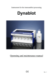
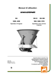
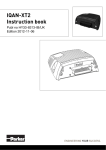
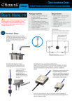
1
Instrument for the immunoblot processing
Dynablot
Service manual
Rev. 2
The knowledge imparted by this manual is required for the some spare part replacing and
adjusting of the instrument. Therefore please make yourself familiar with contents of this
manual
Copyright
Copyright © Revised 2008 Dynex Technologies spol. s r.o..
All rights reserved. Reproduction of the accompanying user documentation in whole or in part
is prohibited.
List of contents :
1
2
3
4
5
6
About this manual .............................................................................................................. 1
Service menu – instrument settings a check....................................................................... 1
2.1 Components test .......................................................................................................... 1
2.2 Home positions setting ................................................................................................ 3
2.3 The strip plate setting .................................................................................................. 4
2.4 Language version ......................................................................................................... 5
2.5 Return to instrument main menu ................................................................................. 6
The arms adjustment procedure ......................................................................................... 6
Hydraulic systems diagram ................................................................................................ 7
Tubing replacement ............................................................................................................ 7
5.1 Dispensing tubing ........................................................................................................ 7
5.2 Waste tubing .............................................................................................................. 10
5.3 Vacuum and exhaust tubing replacement .................................................................. 11
Peristaltic pump head replacement ................................................................................... 12
i
Rev 2.
ii
Rev 2.
1 About this manual
The Service manual has been written for the user (e.g. instruments technician) and provides
information on the Dynablot instrument. This manual contains the components check,
adjustment and part replacement instruction for the Dynablot instrument.
Read the manual in its entirely prior to servicing the instrument.
The Service manual joins with Dynablot Operating and maintenance manual which refers to it
.
2 Service menu – instrument settings a check
WARNING !
The service menu functions could change instrument settins. Use them only with fully
understanding.
Service menu is accesible from Main menu. Press simultaneously
and
for 3 seconds.
Service menu consists of 4 items:
- Components test : checking of motors and pumps
- Home position – set : setting SW constants for arm shift and aspirate arm moving
- Plate - set : setting SW constants for used type of the strip plate
- Language version : setting man to machine dialogue language
2.1
Components test
By means of keys
or
select the function
Service:
Components test
Components test:
Arm shifts
Arm shifts:
ENTER:Home +:right
-:left
1
Rev 2.
- dispensing arm runs into the magnetic sensor from the right direction
- dispensing arm runs into next strip position to right direction up to last strip position
- dispensing arm runs into previous strip position to left direction up to home position
- return to Component test menu
or
By means of keys
select the function
Components test:
Aspirate arm
Aspirate arm:
ENTER:Home +:up
-:down
- aspirating arm runs into the magnetic sensor from the down direction
- aspirating arm runs into upper position
- aspirating arm runs into down position
- return to Component tests menu
By means of keys
or
select the function
Components test:
Rocking
Rocking:
ENTER:Home
+:start
-:stop
- the strip plate rocking cam runs into the home magtetic sensor
- switch on the rocking stepper motor
- switch off the rocking stepper motor, the strip plate rocking carrier stops in the
horizontal position
- return to Component tests menu
By means of keys
or
select the function
2
Rev 2.
Components test:
Peristaltic pump
Peristaltic pump: Pump A
ENTER:next +:forward -:backward
- selecting of next pump (A,B,C,D,E,F,A,B,…….)
- switch on the pump motor in forward direction for about 2 seconds (dispensing)
- switch on the pump motor in backward direction for about 2 seconds (reagent saving)
- return to Component tests menu
By means of keys
or
select the function
Components test:
Aspirate pump
Aspirate pump
+:start -:stop
- switch on the pump motor
- switch off the pump motor
- return to Component tests menu
2.2
Home positions setting
This menu enable to set the left - start position of the dispense arm (Arm shifts) and the lower
position of the aspirating arm (Aspirate arm).
By means of keys
or
select the function
Service:
Home position-set
Home position-set:
Arm shifts
3
Rev 2.
Arm shifts:
ENTER:Save +:right
-:left
- arm runs into right direction by one microstep
- arm runs into left direction by one microstep
Set the position of the dispensing arm above the priming bowl. Both dispensing and aspirating
tubes must lead to the bowl.
- the position of the arm saving
- return to Home position – set menu
By means of keys
or
select the function
Home position-set:
Aspirate arm
Insert the strip plate to the carrier. Setting. It is possible to set the aspirate arm position when
the aspirate arm is adjusted for the used strip plate. (See capter The arms adjustment
procedure).
Aspirate arm:
ENTER:Save +:Up -:Down
The aspirating arm goes above the first strip position.
- aspirating arm runs in up direction by one microstep
- aspirating arm runs in down direction by one microstep
Set the lower aspirating arm position. Run down the arm (button
) as long as the
aspirating tube just touches the strip plate bottom. If you want to repeate setting procedure,
the aspirating arm must be raised and again run down to the bottom position.
- constant of the actual arm position saving
- return to Home position – step menu
2.3 The strip plate setting
This menu enables to set the parametres of used strip plate.
4
Rev 2.
By means of keys
or
select the function
Insert the strip plate to the carrier.
Service:
Plate setting
Set the 1-st strip:
ENTER:Save +:right
or
-:left
- dispensing arm runs into right direction by one microstep or about 5 mm step
or
- dispensing arm runs into left direction by one microstep or about 5 mm
step
Set the position of the dispensing arm. The dispensing tubes must lead to the center of the 1-st
strip.
- the position of the arm saving
Set last strip:
ENTER:Save +:right
or
-:left
- dispensing arm runs into right direction by one microstep or about 5 mm step
or
- dispensing arm runs into left direction by one microstep or about 5 mm
Set the position of the dispensing arm. The dispensing tubes must lead to the center of the last
strip.
- the position of the arm saving
No. of strips:
00
By means of keys
or
set the number of strips at the plate.
- the new plate parameters calculating and saving
2.4
Language version
The instrument memory contains texts in 7 language version : English, Espanol, Portugues,
Italiano, Turkce, Deutsch and Cesky. This menu enables to chose the language of displayed
texts.
5
Rev 2.
By means of keys
or
Service:
Language version
select the function
Language version:
English
By means of keys
or
select required language
setting of the selected language and return to Service menu
2.5
Return to instrument main menu
Press
Exit?
in Service menu
Yes – return to Main menu
No – remain in Service menu
3 The arms adjustment procedure
The arm adjustments consists of 4 successive steps:
1. The left - start position of the dispense arm (Home position – set/Arm shifts) (See
previous capter)
2. The strip plate setting (See previous capter)
3. The aspirating arm mechanical adjustment (See next text)
4. The aspirate arm position setting (Home position – set /Aspirate arm)
The aspirating arm mechanical adjustment
Insert the strip plate to carrier and position the dispense arm above the 1-st strip. Use menu
Service/Components test/Arm shifts for this operation.
After that press ESC and open Service/Components test/Aspirate arm menu.
Now untighten two screws on the aspirating arm and place the aspirating tube above the
center of the 2-nd strip. Then tighten screws and check movement of the aspirating arm By
and
. The aspirating tube must lead to the strip centre down corner
means of keys
( for the best strip content aspiration) but must not collide with the strip plate edge during its
movement. Untighten two screws and make needed correction. After adjustment finishing
tighten the screws well.
6
Rev 2.
4 Hydraulic systems diagram
5 Tubing replacement
For access to instrument remove two screws in the top part of the peristaltic pumps area. Fold
the top part of instrument and secure it in open position.
5.1 Dispensing tubing
Disconnect old tubes from the pump tube-to-tube connectors. Cut off plastic straps which
secured tubes at lower part of dispensing arm. Remove old tubes.
Prepare new tubes. (Silatic, Laboratory Tubing 508-008, 1,57mm x 3,18mm)
The tube lenghts table :
Chanel
Tube length (cm)
A
65
B
58
C
50
D
50
E
54
F
61
Install the new tubes. See next pictures.
7
Rev 2.
Start inserting from the dispensing arm. Keep the chanel order.
The tubec B,C,F are inserted in front of the arm pivot, A,D,E behind it.
Secure the tubing by means of the plastic wrap to the dispensing arm body. Tight wrap
carefully not to press dispense tubing.
Place the spiral belt aroud tubing
8
Rev 2.
Poke the tubes through holes above the pumps and connect them to the tube-to-tube
connectors of the rihgt pump tubes. The left pump tube is the input, the right tube is the
output.
9
Rev 2.
5.2 Waste tubing
Disconnect the tube from the pipe at the aspirating arm and remove it.
Prepare the new tube (Silatic, Laboratory Tubing 508-010, 2,64mm x 4,88mm), lenght
110cm.
Connect the new tube to the aspirating arm pipe, then along the arm back side to the
instrument inside. Secure the tube to top and bottom side of the arm and to plastic holder at
the back instrument side. Then poke the tube by hole Waste in the back side of the instrument
Connect the new tube to the waste bottle to outlet with short tube inside the bottle.
10
Rev 2.
5.3 Vacuum and exhaust tubing replacement
Disconnect the tubes from the diaphragm pump remove them from instrument and disconnect
silencer.
Prepare the new tube (Silatic, Laboratory Tubing 508-010, 2,64mm x 4,88mm)
The tube lenghts table :
Tube position
Tube length (cm)
Diaphragm pump input – waste bottle
60
Diaphragm pump output – silencer
11
Silencer - exhaust
11
Clean the silencer inside and connect 2 short bubes to its outlets. Put silencer to the
instrument and connect ist tubing to the pump output and the exhaust at back side of the
instrument. Pay attention, the tube from the pump output must be connected to silencer outlet
with short tube inside it. Then poke the long tube by hole Vacuum in the back side of the
instrument and connent it to the diaphragm pump input and the waste bottle outlet (without
short tube inside the bottle).
11
Rev 2.
6 Peristaltic pump head replacement
Remove the old peristaltic pump head. Push the locks ( marked by arrows in the picture) and
pull the head from the motor shaft.
Equip the new head tube by 2 pieces tube-to-tube connector (AC-6). Push the black tool to
hole in the front side of the head and mount the head on the motor shaft. Také care to get back
the lock well.
12
Rev 2.