1
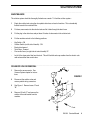
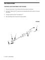
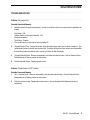
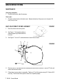
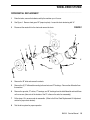
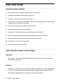
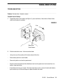
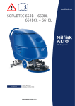
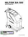
NILFISK BA 500
Service Manual
ORDER PARTS
Online: www.ivie-ent.com
Phone: (918)254-5161
Model 66324400
12/94 Form Number 043023
TABLE OF CONTENTS
________________________________________________________________________________________________________________________________________________________________________________________________________________________________________________________________________
Batteries .................................................................................................................21
Brush Drive Belt Adjustment Or Replacement .........................................................7
Brush Drive Motor - Carbon brush Inspection ......................................................... 8
Brush Drive Motor Replacement ............................................................................. 8
Brush Drive System Maintenance ............................................................................7
Brush Drive System Troubleshooting .....................................................................10
Differential Replacement ........................................................................................16
Potentiometer Adjustment ......................................................................................20
Safety .......................................................................................................................1
Solenoid Valve - Removal / Disassembly & Cleaning ..............................................4
Solution System Maintenance ..................................................................................4
Solution System Troubleshooting .............................................................................6
Specifications & Maintenance ..................................................................................2
Squeegee Adjustment ............................................................................................13
Vacuum Motor Removal .........................................................................................12
Vacuum System Maintenance ................................................................................ 11
Vacuum System Troubleshooting ...........................................................................14
Wheel Drive Chain - Replacement Or Adjustment .................................................17
Wheel Drive Motor Replacement ...........................................................................17
Wheel Drive System Troubleshooting ....................................................................18
Note: All references to right, left, front, or rear in this manual are as seen from the operator’s stand-point.
SAFETY
________________________________________________________________________________________________________________________________________________________________________________________________________________________________________________________________________
SYMBOLS
Nilfisk uses the symbols below to signal potentially dangerous conditions. Always read this information
carefully and take the necessary steps to protect personnel and property.
DANGER!
Is used to warn of immediate hazards that will cause severe personal injury or death.
WARNING!
Is used to call attention to a situation that could cause severe personal injury.
CAUTION!
Is used to call attention to a situation that could cause minor personal injury or damage to the machine or other
property.
________________________________________________________________________________________________________________________________________________________________________________________________________________________________________________________________________
GENERAL SAFETY INSTRUCTIONS
WARNING!
Keep sparks, flame and smoking materials away from the batteries. Explosive gases are vented during
normal operation.
Remove all jewelry when working near electrical components.
Disconnect one of the battery terminals when servicing electrical components.
Never work under a machine without safety stands or blocks to support the machine.
CAUTION!
Carefully read all instructions pertaining to a service function before performing that function.
Take precautions to prevent hair, jewelry, or loose clothing from becoming caught in moving parts.
1
BA 500 Service Manual
SPECIFICATIONS
________________________________________________________________________________________________________________________________________________________________________________________________________________________________________________________________________
SPECIFICATIONS
Dimensions
Scrub Brush Diameter
Scrub Brush Path
Scrub Brush Pressure
Scrub Brush Speed
Squeegee Size
Machine Length
Machine Width
Machine Height
Drive Wheel
Solution Tank Capacity
Recovery Tank Capacity
Coverage Rate
Machine Weight
General Specifications
Brush Motor
Wheel Drive Motor
Vacuum Motor
Brush Drive
Sound Level
Squeegee Type
Speed Control
Batteries
English (Metric)
20 inches (51 cm)
20 inches (51 cm)
70 lbs (32 kg)
190 rpm (190 rpm)
25.5 inches (65 cm)
44 inches (112 cm)
21.75 inches (55 cm)
43.5 inches (110 cm)
8 inch (20 cm) soft ride wheels
12 gal (45i)
12 gal (45i)
7,500 sq ft (697 m2) per hour
266 lbs (121 kg) net w/o batteries
558 lbs (253 kg) w/four 244 AH batteries
376 lbs (175 kg) w/two 93 AH batteries
350 lbs (159 kg) shipping weight
24 volt, 1/2 hp dc motor
24 volt, 1/4 hp dc motor
24 volt, 3/4 hp dc motor
Belt drive
68.2 db (A) @ 3 ft (.9m) using pads
68.9 db (A) using prolene scrub brushes
4 sided, curved, pivot type
Electronic, fully variable forward/reverse
(4) 6 volt 244 AH (std)
(2) 12 volt 93 AH (opt)
BA 500 Service Manual
2
MAINTENANCE
________________________________________________________________________________________________________________________________________________________________________________________________________________________________________________________________________
MAINTENANCE CHART
MAINTENANCE ITEM
Clean and inspect the tanks and hoses
Clean the brushes and pads
Clean the squeegee
Charge the batteries
Check battery water level
Lubrication
Vacuum motor carbon brushes
Daily
X
X
X
X
Once a
Week
Once a
Month
X
X
X
ORDER PARTS
Online: www.ivie-ent.com
Phone: (918)254-5161
3
BA 500 Service Manual
Once a
Year
SOLUTION SYSTEM
________________________________________________________________________________________________________________________________________________________________________________________________________________________________________________________________________
MAINTENANCE
The solution system should be thoroughly flushed once a week. To flush the solution system...
1
Empty the solution tank, using the clear plastic drain hose on back of machine. This automatically
flushes loose dirt from solution filter.
2
Put clean, warm water into the solution tank and let it drain through the drain hose.
3
Put the plug in the drain hose and put about 2 inches of clean water in the solution tank.
4
Put the machine controls in the following positions:
•
•
•
•
•
Key Switch - ON
Solution Switch (on left side of handle) - ON
Brush drive lowered
Twist Grips - Forward
Flow control lever (on right side of control handle) UP
•
Let all of the clean water flow from the tank. This will flush dirt and soap residue from the electric solenoid valve and the flow control valve.
________________________________________________________________________________________________________________________________________________________________________________________________________________________________________________________________________
SOLENOID VALVE REMOVAL
1
2
Remove the vacuum motor. See
Vacuum System chapter for instructions.
Disconnect the solution valve and
mercury switch wiring connectors.
3
See Figure 1. Remove hoses “A” and
“B”.
4
Remove (2) bolts “C” and remove the
solution valve and bracket from the
machine.
A
FIGURE 1
B
C
Front
BA 500 Service Manual
4
SOLUTION SYSTEM
________________________________________________________________________________________________________________________________________________________________________________________________________________________________________________________________________
SOLENOID VALVE DISASSEMBLY AND CLEANING
1
Remove the solenoid valve. See the Solenoid Valve Removal section for instructions.
2
See Figure 2. Remove the (2) “D” screws and nuts and disassemble the valve (be careful not to lose any
internal parts).
3
Thoroughly wash dirt from block “E” and diaphram “F”.
4
After reassembling, test the solenoid valve for proper operation.
FIGURE 2
D
E
D
5
BA 500 Service Manual
F
SOLUTION SYSTEM
________________________________________________________________________________________________________________________________________________________________________________________________________________________________________________________________________
TROUBLESHOOTING
________________________________________________________________________________________________________________________________________________________________________________________________________________________________________________________________________
Problem: No solution flow
Possible Cause and Remedy:
1 Machine controls not positioned properly. In order for solution to flow, the controls must be positioned as
follows:
•
•
•
•
•
Key Switch - ON
Solution Switch (on left side of handle) - ON
Brush drive lowered
Twist Grips - Forward
Flow control lever (on right side of control handle) UP
2
Clogged Solution Filter. Drain solution tank, using the clear plastic drain hose on back of machine. This
automatically flushes loose dirt from solution filter. If solution still does not flow, remove and disassemble
the tee-fitting (under the solution tank), remove and clean the filter thoroughly.
3
Clogged Solenoid Valve. Remove, disassemble, and clean the solenoid valve. See the Solenoid Valve
Disassembly and Cleaning section for instructions.
4
Defective Speed Control. Replace speed control.
________________________________________________________________________________________________________________________________________________________________________________________________________________________________________________________________________
Problem: Solution leaks in “OFF” position
Possible Cause and Remedy:
1 Dirt in solenoid valve. Remove, disassemble, and clean the solenoid valve. See the Solenoid Valve
Disassembly and Cleaning section for instructions.
2
Defective solenoid valve. Replace the solenoid valve. See the Solenoid Valve Removal section for
instructions.
BA 500 Service Manual
6
BRUSH DRIVE SYSTEM
________________________________________________________________________________________________________________________________________________________________________________________________________________________________________________________________________
MAINTENANCE
Once every six months...
1 Check the belt tension, adjust if necessary.
Once a year...
1 Check the carbon brushes in the brush motor. Replace the brushes if they are worn to a length of 3/8
inch (10 mm) or less.
________________________________________________________________________________________________________________________________________________________________________________________________________________________________________________________________________
BELT ADJUSTMENT OR REPLACEMENT
FIGURE 1
1
Drain the solution and recovery tanks.
2
See Figure 1. Tip the machine back as
shown and place a jack stand under the
front end.
3
See Figure 2. Turn nut “A” counterclockwise to loosen the belt tension.
A
D
C
FIGURE 2
E
D
C
B
Front
4
Remove screw “B” and remove the idler assembly and the belt from the machine. Remove “E” bolts, and
remove the belt from the idler.
5
Follow steps in reverse order to reassemble. Tighten nut “A” until the tension spring is 2 1/2 inches (63.5
mm) long. Test the brush drive system to make sure it operates properly.
7 BA 500 Service Manual
BRUSH DRIVE SYSTEM
________________________________________________________________________________________________________________________________________________________________________________________________________________________________________________________________________
BRUSH DRIVE MOTOR - CARBON BRUSH INSPECTION
1
Remove the brush drive motor. See the Brush Drive Motor Replacement section for instructions.
2
See Figure 3. Place the brush drive motor in a vice as shown. Be careful not to damage the pulley.
FIGURE 3
F
F
FIGURE 4
3
See Figure 4. Remove (2) “F” nuts and remove the end bell from the motor.
4
Remove and measure the carbon brushes. If they are worn to 3/8 inch (9.66 mm) or shorter, replace
both carbon brushes. Remove all loose carbon and dirt from the inside of the motor.
5
Follow steps 1-3 in reverse order to reassemble.
6
Test the motor to make sure it operates properly.
________________________________________________________________________________________________________________________________________________________________________________________________________________________________________________________________________
BRUSH DRIVE MOTOR REPLACEMENT
1
Drain the solution and recovery tanks and remove the solution tank from the machine.
2
Tip the recovery tank to the side and disconnect the batteries.
3
Remove the vacuum motor. See the Vacuum System section for instructions.
4
Disconnect the wires from the brush drive motor. Take note of which wire color goes to each terminal for
reassembly.
BA 500 Service Manual
8
BRUSH DRIVE SYSTEM
________________________________________________________________________________________________________________________________________________________________________________________________________________________________________________________________________
BRUSH DRIVE MOTOR REPLACEMENT, (continued)
5
See Figure 5. Tip the machine back as
shown and place a jack stand under the
front end.
6
See Figure 6. Turn nut “G” counterclockwise to loosen the belt tension.
G
J
FIGURE 5
I
FIGURE 6
K
J
I
H
Front
7
Remove screw “H”, the idler assembly and the belt from the machine.
8
Remove (2) “I” bolts and (2) “J” nuts. Set the front of the machine back on the floor and pull the brush
drive motor up and out of the machine.
9
Remove the pulley from the old motor and install it on the new one.
10 Follow steps 1-7 in reverse order to reassemble. Tighten nut “G” until the tensioning spring is 2 1/2
inches (63.5 mm) long.
11 Test the brush drive system.
9 BA 500 Service Manual
BRUSH DRIVE SYSTEM
________________________________________________________________________________________________________________________________________________________________________________________________________________________________________________________________________
TROUBLESHOOTING
________________________________________________________________________________________________________________________________________________________________________________________________________________________________________________________________________
Problem: Squealing noise when brush is lowered.
Possible Cause and Remedy:
1 Loose belt — adjust belt tension.
________________________________________________________________________________________________________________________________________________________________________________________________________________________________________________________________________
Problem: Brush motor will not start when twist grips are turned.
Possible Cause and Remedy:
1 Tripped brush motor circuit breaker (see
Figure 7) — press the reset button, check
circuit breaker for continuity.
2
Defective brush motor solenoid (see
Figure 7) — replace solenoid.
3
Defective brush motor switch (see Figure
7) — replace switch.
4
Defective brush motor — remove motor,
repair or replace.
5
Defective speed control or potentiometer
— replace speed control or potentiometer.
FIGURE 7
Brush
Drive
Circuit
Breaker
Brush Drive
Solenoid
Front
Brush Motor Switch
BA 500 Service Manual
10
VACUUM SYSTEM
________________________________________________________________________________________________________________________________________________________________________________________________________________________________________________________________________
MAINTENANCE
Whenever the vacuum system does not perform
properly, the entire system should be cleaned and
inspected, following the maintenance checklist
below.
1
Remove the squeegee from the machine and
clean it thoroughly.
2
Inspect the squeegee blades. If the wiping
edge of the rear blade is damaged or worn to
a radius, turn it around or over so a new
edge with a sharp corner faces toward the
front of the machine.
3
FIGURE 1
B
Front
F
E
See Figure 1. Disconnect squeegee hose
“A” from left side of recovery tank cover “B”.
Park the machine outside or near a floor
drain and use a garden hose to “back flush”
dirt down and out of squeegee hose “A”.
CAUTION!
C
A
D
Do not flush hose “C” unless it is disconnected
from the vacuum motor.
4
Remove cover “B” from the recovery tank
(see Figure 1). Rinse all dirt from cage “E”
and ball “F”.
5
Check the gasket on recovery tank cover “B”.
It must seal air-tight against the top of the
tank.
6
Check drain hose cap “D”. Replace the cap if it does not seal air-tight.
If the machine still does not pick up after completing this checklist, see the Troubleshooting section of this
chapter for additional information.
11
BA 500 Service Manual
VACUUM SYSTEM
________________________________________________________________________________________________________________________________________________________________________________________________________________________________________________________________________
VACUUM MOTOR REMOVAL
FIGURE 2
1
Drain the recovery tank, and tip it to the side of
the machine.
2
Drain the solution tank, disconnect the hose
from the bottom of the tank and remove the
tank from the machine.
3
Disconnect one of the battery cables.
4
See Figure 2. Remove the (4) “G” screws and
lift cover “H off of the machine, along with
G
I
H
G
bracket “I”.
5
See Figure 3. Remove the (4) “J” screws.
6
Disconnect the vacuum motor wiring connector.
7
Disconnect hose “K” from the vacuum motor assembly and remove the motor from the machine.
J
FIGURE 3
Front
K
BA 500 Service Manual 12
VACUUM SYSTEM
________________________________________________________________________________________________________________________________________________________________________________________________________________________________________________________________________
SQUEEGEE ADJUSTMENT
1
Adjust the large knob “M” on the back of the squeegee mount until both front and rear blades touch the
floor equally.
FIGURE 4
M
Front
13
BA 500 Service Manual
VACUUM SYSTEM
________________________________________________________________________________________________________________________________________________________________________________________________________________________________________________________________________
TROUBLESHOOTING
________________________________________________________________________________________________________________________________________________________________________________________________________________________________________________________________________
Problem: Machine will not pick up water, water flows around ends of squeegee.
Possible Cause and Remedy:
1 Cap for recovery tank drain hose not sealing air-tight — install cap properly or replace if damaged.
2
Recovery tank cover not installed properly — push cover down all the way, so it seals air-tight against the
top of the tank.
3
Damaged gasket on recovery tank cover — replace gasket.
4
Low battery voltage — charge or replace batteries.
5
Vacuum motor defective — repair or replace vacuum motor.
________________________________________________________________________________________________________________________________________________________________________________________________________________________________________________________________________
Problem: Water in vacuum motor
Possible Cause and Remedy:
1 Operator using high-sudsing detergent — use low-sudsing detergent or add a defoaming chemical to the
recovery tank.
2
Vacuum leak in recovery tank drain hose or cap — replace hose or cap.
3
Vacuum shut-off float ball not closing — clean or replace float ball and cage (mounted on recovery tank
cover).
________________________________________________________________________________________________________________________________________________________________________________________________________________________________________________________________________
Problem: Float closes before tank is full
Possible Cause and Remedy:
1 Foam in recovery tank — advise operator to use low-sudsing detergent or add a defoaming chemical to
the recovery tank.
2
Cage around vacuum shut-off float clogged — disconnect hoses from recovery tank cover, remove the
cover and clean or replace the float cage.
BA 500 Service Manual 14
VACUUM SYSTEM
________________________________________________________________________________________________________________________________________________________________________________________________________________________________________________________________________
TROUBLESHOOTING, (continued)
________________________________________________________________________________________________________________________________________________________________________________________________________________________________________________________________________
Problem: Vacuum motor will not run when squeegee is lowered
Possible Cause and Remedy:
1 Tripped vacuum motor circuit breaker (see
Figure 5) — press reset button, check circuit
breaker for continuity.
2
Defective vacuum switch (see Figure 6) —
remove cover panel from back of control
handle, adjust or replace switch.
3
Defective vacuum motor — remove motor,
repair or replace.
4
Defective vacuum motor solenoid — replace
solenoid.
FIGURE 5
Vacuum Motor
Solenoid
Vacuum Motor
Circuit Breaker
Front
FIGURE 6
Vacuum Motor Switch
15
BA 500 Service Manual
WHEEL DRIVE SYSTEM
________________________________________________________________________________________________________________________________________________________________________________________________________________________________________________________________________
DIFFERENTIAL REPLACEMENT
1
Drain the tanks, remove the batteries and tip the machine up on it’s nose.
2
See Figure 1. Remove chain guard "K" (snaps in place). Loosen the chain tensioning bolt “A”.
3
Disconnect the master link in the chain and remove the chain.
FIGURE 1
H
C
C
E
D
I
K
A
G
F
Front
J
B
4
Remove the “B” bolts and remove the wheels.
5
Remove the (6) "C" differential mounting bolts and nuts and “D” bushings. Remove the differential from
the machine.
6
Remove the sprocket, “E” collars, “F” bearings, and “G” bushings from the old differential and install them
on the new one, (take note of the location of the “E” collars on the axles for reassembly).
7
Follow steps 1-5 in reverse order to reassemble. (Refer to the Drive Chain Replacement Or Adjustment
section for proper chain tension).
8
Test the drive system for proper operation.
BA 500 Service Manual
16
WHEEL DRIVE SYSTEM
________________________________________________________________________________________________________________________________________________________________________________________________________________________________________________________________________
DRIVE MOTOR REPLACEMENT
1
Drain the tanks, remove the batteries and tip the machine up on it’s nose.
2
Disconnect the squeegee lift cable and the squeegee hose.
3
See Figure 1. Remove chain guard "K" (snaps in place).
4
Loosen lock nut “J” and turn bolt “A’ to loosen the chain tension (On reassembly, refer to the Drive Chain
Adjustment section for proper chain tensioning).
5
Disconnect the master link on the chain and remove the chain.
6
Disconnect the drive motor from the wiring harness.
7
Remove the (2) “I” bolts and nuts and remove the drive motor from the machine.
8
Remove the old drive motor from the motor mount and install the new motor on the mount.
9
Remove the chain guard “H” from the old motor and install it on the new one.
10 Follow steps 1-6 in reverse order to reassemble.
11 Test the drive system for proper operation.
________________________________________________________________________________________________________________________________________________________________________________________________________________________________________________________________________
DRIVE CHAIN REPLACEMENT OR ADJUSTMENT
________________________________________________________________________________________________________________________________________________________________________________________________________________________________________________________________________
Replacement:
•
Refer to steps 1, 3 & 4 of the Drive Motor Replacement section for instructions. Follow these steps in
reverse order to reassemble.
________________________________________________________________________________________________________________________________________________________________________________________________________________________________________________________________________
Adjustment:
•
See Figure 1. Loosen the lock nut “J”, turn bolt “A” to tighten or loosen the chain. There should be about
1/2 inch (12 mm) of deflection between the sprockets when moderate pressure is applied to the chain.
•
After replacing or adjusting the chain, test the drive system for proper operation.
17
BA 500 Service Manual
WHEEL DRIVE SYSTEM
________________________________________________________________________________________________________________________________________________________________________________________________________________________________________________________________________
TROUBLESHOOTING
________________________________________________________________________________________________________________________________________________________________________________________________________________________________________________________________________
Problem: No wheel drive - forward or reverse
Possible Cause & Remedy:
1 Tripped wheel drive circuit breaker (see Figure 2) - press reset button, if wheel drive still doesn’t work,
check circuit breaker for continuity.
FIGURE 2
Front
Wheel Drive
Circuit Breaker
2
Defective wheel drive motor - follow instructions below.
•
Jack up the rear of the machine to lift the drive wheels off the floor.
•
Remove back panel from control handle.
•
Remove the plastic cover from the speed control.
•
Disconnect the brown/yellow and the white/brown wires from the speed control and connect them to a
battery, using jumper wires.
•
If the wheel motor turns, go to step 3. If the wheel motor does not turn, remove the tanks and batteries,
tip the machine up on its nose and repair or replace the wheel drive motor.
BA 500
Service Manual
18
WHEEL DRIVE SYSTEM
________________________________________________________________________________________________________________________________________________________________________________________________________________________________________________________________________
TROUBLESHOOTING, (continued)
3
Defect in potentiometer mechanism - follow instructions below.
•
Make sure that the orange, yellow and green wires are firmly connected to the potentiometer (see Figure
3).
•
See Figure 3. Check for loose set screws in pulley “B” or” C”.
•
If the wires and set screws are both secure, follow steps below.
•
Remove the plastic cover from the speed control.
•
Disconnect plug “A” from the speed control.
•
Connect an ohmmeter to the green and orange wires. NOTE: inserting the ends of paper clips into the
plug will help in the attachment of the test leads. The meter should read 2400 - 2600 ohms in neutral and
increase to 5000 ohms when the twist grips are turned to the full-forward position. If you do not get
these readings, follow potentiometer adjustment instructions. If you do get these readings, go to the next
test.
•
Connect an ohmmeter to the green and yellow wires. The meter should read 2400 - 2600 ohms in
neutral and decrease to 100 - 300 ohms when the twist grips are turned to the full forward position. If you
do not get these readings, follow potentiometer adjustment instructions. If you do get these readings,
the potentiometer is OK - replace the speed control.
FIGURE 3
C
Yellow
Green
B
Orange
D
A
19
BA 500
Service Manual
WHEEL DRIVE SYSTEM
________________________________________________________________________________________________________________________________________________________________________________________________________________________________________________________________________
POTENTIOMETER ADJUSTMENT
Adjust the potentiometer if the machine has no drive, or if it moves with the twist grips in neutral. To adjust the
potentiometer...
1
Remove the back panel from the control handle.
2
See Figure 3. Loosen the (2) set screws in pulley “B”.
3
Remove the plastic cover from the speed control.
4
Carefully pull connector “A” off the speed control (pull toward back of machine).
5
Connect an ohmmeter (on 0 x 100 scale) to the green and yellow wires at the connector.
6
Turn the potentiometer shaft until the meter reads between 2400 and 2600 ohms.
7
Without turning the potentiometer shaft, tighten the set screws in pulley “B”.
8
Test the drive system for proper operation before installing speed control cover and handle cover.
BA 500
Service Manual
20
BATTERIES
________________________________________________________________________________________________________________________________________________________________________________________________________________________________________________________________________
WARNING!
Use extreme caution when working with batteries. Sulfuric acid in batteries can cause severe injury if allowed
to contact skin or eyes.
Explosive hydrogen gas is vented from inside the battery caps. This gas can be ignited by any electrical arc,
spark, or flame.
When working with batteries:
•
Remove all jewelry
•
Wear safety glasses
•
Do not smoke
•
Do not allow tools to touch more than one battery terminal at a time
•
Work in a well ventilated area
________________________________________________________________________________________________________________________________________________________________________________________________________________________________________________________________________
BATTERY MAINTENANCE
Proper maintenance of electric vehicle batteries can greatly extend their life.
There are 3 simple rules for good battery maintenance:
•
Maintain Proper Electrolyte Level - Use distilled water in batteries whenever possible. If batteries are
discharged, add just enough water to cover the plates in each cell. If batteries are fully charged, fill each
cell to the bottom of the filler tube. Do not over-fill the batteries! Do not add acid to batteries!
•
Keep the Batteries Charged - Batteries should be charged each time that a machine is used for more
than 1 hour. Machine operators should tip the solution tank forward and the recovery tank to the side of
the machine for charging, to avoid a concentrated build-up of hydrogen gas. Operators should follow the
instructions provided with their specific battery charger, to determine how long the batteries should be
charged. Even when a machine is stored, the batteries should be charged once a month to prevent the
batteries from “sulfating”. Almost all battery caps are vented, so there’s no need to loosen or remove
them for charging.
21
BA 500
Service Manual
BATTERIES
________________________________________________________________________________________________________________________________________________________________________________________________________________________________________________________________________
BATTERY MAINTENANCE, (continued)
•
Keep the Batteries Clean - Use a damp cloth to wipe dirt and liquid from the top of the batteries. Battery
terminals must be clean and tight. If the top of the batteries are wet after charging, the batteries have
probably been over-filled.
________________________________________________________________________________________________________________________________________________________________________________________________________________________________________________________________________
BATTERY TESTING
A battery problem is usually recognized by the machine operator, as a decrease in the machine’s running time.
This condition is usually caused by one (or more) “dead cell(s)” in the battery system- that is, one (or more)
cell(s) that is putting out less voltage than the other cells.
Note: Always charge batteries before testing.
There are 2 ways to find a dead cell:
•
Use a hydrometer to check the specific gravity (or “state of charge”) of the fluid in each cell. A dead cell
is one that reads 50 points (or more) lower than the other cells.
•
Use a volt meter to check the voltage of each battery with the brush and vac motors running. The battery
with the dead cell will read 1 or 2 volts lower than the other batteries in the system.
If the batteries in the machine are more than 1 year old, it’s usually best to replace the whole set, rather than
replacing just one battery.
BA 500 Service Manual 22