1
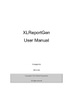
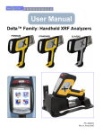
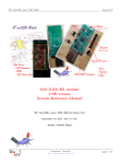
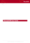
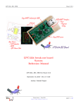
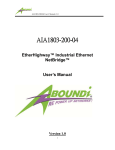
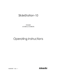
Quick Start Guide
DELTA Family of Handheld XRF Analyzers
PREMIUM
STANDARD
CLASSIC
Table of Contents
Quick Start Guide
Table of Contents
1
DELTA Family
2
Unpack Carry Case
3
Tour: Analyzer
4
Tour: Docking Station
Type
Modes
Models
5
Components & Accessories
Premium
Alloy
DP-2000
5
Return Procedures
Environmental
DP-4000
6
Safety Information
Mining
DP-6000
7
Warning Label & Indicators
RoHS
DP-6500
Innov-X Systems, Inc.
8
Prepare for Operations
Alloy
DS-2000
100 Sylvan St.
8
Battery Issues
Environmental
DS-4000
Woburn, MA 01801 USA
9
Snapshot of User Interface
Mining
DS-6000
10
GUI Elements: Icons/Buttons
RoHS
DS-6500
11
Typical Operating Procedures
Alloy
DC-2000
12
Append A: Radiation Profile
Delta Models
Standard
Classic
Environmental
DC-4000
Mining
DC-6000
RoHS
DC-6500
PN 103076
Rev. 2.0: 8/2010
DELTA Family Handheld™ XRF Analyzers
Unpack the Instrument and Docking Station
To
1.
2.
3.
4.
unpack the instrument:
Locate and remove the shipping papers and documentation.
Open the Carrying Case and remove the Delta and all of the components
Note that the protective foam has TWO LAYERS.
With the Foam Top Layer clear of items, lift it to expose the Docking Station
and the optional AC Power Adapter
5. Inspect all components for damage and report any to Innov-X immediately.
ITEM CHECKLIST for DELTA Handheld XRF Analyzer
1
o
Foam: Top Layer
2
o
Component Key
Cutout
—Foam: Top Layer—
1
Carry Case
2
Delta Analyzer
3
Docking Station Charger
4
USB Cable #1 (See pg 5 for details)
5
USB Cable #2 (See pg 5 for details)
6
Li-ion Batteries (2)
7
Cal Check Coupon
8
Extra Windows (Bag of 10)
9
End/User Documentation
7
o
3
o
o
6
4
o
5
o
9
o
8
o
—Foam: 2nd Layer—
10
Docking Station
11
AC Power Adapter (Optional)
10
o
11
o
Foam: 2nd Layer
2
— Unpack the Instrument and Docking Station —
Rev. 2.0: 8/2010
PN 103076
DELTA Family Handheld™ XRF Analyzers
Tour of Instrument
1. Handheld Analyzer
Component Key
10
o
Delta - All Models
3
o
1
Delta Analyzer
2
Probe
3
Measurement Window
4
Hinged Window Plate
5
Docking Station Connector
6
Trigger
7
Handle - Non-Slip Rubber Grip
8
Battery Boot
9
Data Port w/ Rubber Cover
10
Heat Sink
11
I/O (Power) Switch w/ LED Indicator
12
X-ray Warning Light Array
13
Touchscreen for User Interface
14
Navigation Keys
(Premium Model Shown)
1
o
(Prolene Film)
2
o
4
o
•
•
5
o
6
o
7
o
10 •
o
o
12
• o
8
o
11
13
o
10 Heat
o
Sink
9
o
14
o
•
•
12
o
11
o
11 I/O Power Switch w/LED Indicator
o
12 X-ray Warning Light Array
o
Rev. 2.0: 8/2010
PN 103076
— Tour of Instrument —
3
DELTA Family Handheld™ XRF Analyzers
2. Docking Station
Component Key
1
o
Delta - All Model
4
o
3
o
2
o
1
Docking Station (Empty)
2
Analyzer Signal/Control Connector
3
Second Battery Charge Socket
4
CalCheck Test Cup (316 stainless steel)
5
Docking Station (Loaded)
6
Second Battery in Socket
7
Data Port(s): — Docking Station ->Rear
— Analyzer -> Left Side
8
Input Power (12 VDC)
9
Indicator Lights
a
Second Battery Charging
b
Analyzer Engaged
5
o
6
o
7
o
7
o
7
o
8
o
9
o
8
o
9
o
3
o
9
o
7
o
4
— 2. Docking Station —
a
o
8
o
b
o
Rev. 2.0: 8/2010
PN 103076
DELTA Family Handheld™ XRF Analyzers
3. Components and Accessories
Items included with a Delta analyzer and docking station are shown below.
Unless otherwise noted, all parts are standard accessories.
Li-ion batteries
High capacity, 4.8-5.2 Ah; two provided (one shown).
USB Cable #1
Six feet, 480 Mbps, USB A to USB B connectors.
USB Cable #2
Mini B to USB A connector.
Kapton Windows - Classic Model only
CalCheck (Standardization) Coupon.
Bag with 10 pieces of 6 μm film windows.
(Not shown)
Prolene Windows - Premium & Standard Models
Bag with 10 pieces of 6 μm film windows.
(Not shown)
AC Power Adapter
AC Power Adapter
Provides DC power to Docking Station;
Input: 110-240 VAC; Output: 60 W, 12 VDC, 5 A.
Li-ion battery replacement; 110 - 240 VAC power
source. This unit is an Optional Accessory.
Delta Documentation Suite
User Manual (P/N 103201))
User SW Interface Guide (P/N 103202)
(Not shown)
Safety and Informational Package
(Not shown)
Packing and Shipping
If the instrument is not returned in the protective case, it can be damaged during shipping. Innov-X Systems
reserves the right to void the warranty on instruments that are damaged during return shipping that are sent
without the protective case.
Prior to returning a unit, customers must contact Customer Service at 1-781-938-5005 or
[email protected] to receive the required RMA number and to answer any shipping questions.
Follow these instructions to return your XRF Analyzer:
1.Pack the analyzer in the black protective case in which it arrived, using the original packing materials.
2.Include the RMA in the case and reference the RMA number in your shipping documents.
3.Close the protective case and either:
• Secure it with plastic zip ties,
— or —
• Pack the protective case within another box.
Rev. 2.0: 8/2010
PN 103076
— 3. Components and Accessories —
5
DELTA Family Handheld™ XRF Analyzers
Radiation Safety Information
Innov-X’s Handheld XRF Analyzers are secure and dependable instruments when used according to
recommended testing techniques and safety procedures.
WARNING
•
•
•
Innov-X analyzers must be used by trained and authorized operators, according to proper safety
procedures. Improper usage may circumvent safety protections and could potentially cause harm
to the user.
Heed all warning labels and messages.
DO NOT USE the instrument if there is any chance that it is damaged or might unintentionally emit
stray radiation. In such a case, arrange for qualified personnel to perform a radiation safety test
and repair any analyzer damage.
Safety Interlock Structure
For controlling an Innov-X handheld instrument’s X-ray emissions, and therefore minimizing the
possibility of accidental exposure, there is a standard safety interlock structure consisting of the
three features listed below.
1. Software Proximity Sensor
•
Within one second of a test start, the analyzer will detect a sample in front of the
measurement window. If not, to prevent accidental exposure, the test aborts, the filter
wheel goes to position 0, and the x-rays shut off. The tube current is reduced to 0.0
microAmperes and the red light stops blinking. Also when a test is in progress, if the
probe/nose is pulled away from the sample, the test stops in approximately one second.
2. Software Trigger Lock
•
If five minutes elapse between tests (default time), the trigger locks automatically and you
must tap on the lock icon
to unlock it.
3. Safeguards
As an owner of an Innov-X handheld XRF instrument your safeguards include those items noted
below:
Limited Access
Keep the instrument in a controlled location, where only trained and authorized users are likely to
have access.
Trained Operators
Keep a sign with the analyzer indicating that in order to use it an operator must have completed a
training class provided by your company, or must have attended an Innov-X training course and
completed any other requirements as dictated by the local regulating authority. When the Innov-X
system is turned on, the controller screen displays a message indicating that the system should
only be used by authorized personnel.
Shielding Issues
BACKGROUND:
An Innov-X handheld XRF instrument emits a tightly collimated beam of X-ray radiation. Although
attenuation occurs, the beam may project many meters in open air.
ACTION:
Adequate shielding is achieved by:
• Establishing a no-admittance zone sufficiently distant from the instrument’s measurement
window that allows air to attenuate the beam.
• Enclosing the beam working area with protective panels (for example, 3.0 mm stainless steel
can attenuate the beam to background levels)
Contact your Innov-X Systems representative for assistance and suggestions on interlocks and
applications for limiting radiation exposure.
Trigger Issues
“Deadman trigger” mode requires the user to PULL AND HOLD the trigger for the DURATION of the
test. Releasing the trigger immediately aborts the test.
6
— Radiation Safety Information —
Rev. 2.0: 8/2010
PN 103076
DELTA Family Handheld™ XRF Analyzers
Warning Label and Indicators
Indicators and Status
Power Switch with Integral Indicator Light
The power switch is located at the upper rear of the unit.
POWER ON
• Press the I/O switch to turn on the power.
— A green LED indicator comes on.
• This switch DOES NOT turn on the x-ray tube.
— No tube power is supplied until the Innov-X software is
launched.
SLEEP
• With the unit running, press I/O switch for an instant.
— Analyzer goes into a “Sleep” state; screen is off;
no further activities are possible.
— The Green LED shows a variable intensity, going from dim
to bright to dim in a repeating fashion.
• Press the switch for an instant again to restore the UI screen.
POWER OFF
• Press and hold switch for >3 seconds.
— Unit powers off. (See page 11 for more Exit options)
Caution Radiation Label:
Underneath Probe/Nose
UI Screen Note
X-Ray
Indicator
LED Array
Power
Switch
All User Interface screens have a time-out (power-saving)
feature that causes a screen to go blank if the UI is not
accessed or the unit is not moved after a 90 second interval.
However, the analyzer is still running.
Restore the screen by tapping it or by moving the unit.
t
X-Ray Indicator
The X-ray indicator is located on the upper rear of the unit.
It consists of a six red LED array.
It provides TWO KEY FUNCTIONS:
•
•
1. X-RAY INDICATOR ON CONTINUOUSLY (SOLID RED LED ARRAY)
This signifies:
• X-ray tube is enabled.
• There is no radiation exposure to you or bystanders.
The instrument can be carried or set down safely in this condition.
2. X-RAY INDICATOR ON FLASHING (BLINKING RED LED ARRAY)
This signifies:
• X-ray tube is powered to full operational level.
• Analyzer is emitting x-ray radiation through the analysis window.
In this condition, the analyzer must be pointed at a test sample.
Test Screen
When making a CalCheck or testing a sample, the TEST screen’s
lower status bar provides an indication of the progress.
Upon completion, message indicates Ready (for next operation)
Rev. 2.0: 8/2010
PN 103076
— Warning Label and Indicators —
7
DELTA Family Handheld™ XRF Analyzers
PREPARATION for Operations - Battery Issues
1. Battery Status
To test a Li-ion Battery’s charge status, press the white button on the battery.
The green lamps indicate the percent of charge, from less than 25% to 100%.
If a battery has a charge of less than 25%, use the Docking Station to establish
a full charge.
2. Charging Batteries
The Delta analyzer has a new multi-purpose tool: a Docking Station. {See Page 4 for hardware details}
In addition to providing an automatic Calibration Check, the Docking Station delivers two
charging functions:
— It can charge the installed Li-ion battery located in the instrument’s handle.
— Simultaneously, it can charge a second battery with its special battery charging
socket.
Charge status is shown in real-time on the Delta’s display screen.
The second docked battery’s status (either “charging = red” or “full = green”) is also
shown on the battery icon located on the rear left side of the Docking Station.
3. HOT SWAP for a Delta Battery
A battery Hot Swap capability is a standard feature with the Delta analyzer.
An operator can remove and replace a battery without having to shut down,
restart, or Cal Check.
A “Shutdown” status display gives the percentage of internal charge remaining when the battery is removed.
If the internal charge reaches 0 you have to re-start the unit with the
I/O switch, after inserting a fresh battery.
If red X-ray indicator lights flash, the battery voltage is too low.
4. Changing a Battery
To CHANGE the battery:
1. Hold the instrument by the handle,
upside down, so the bottom of the
instrument base is pointing upward
with the nose pointing away from the
operator.
2. Pull the rubber latch and lift cover.
3. Remove the existing battery using the
tab.
4. Insert the charged battery into the
analyzer with the battery connectors
facing to the left. The battery slot is
keyed so that the battery can be
inserted only one way.
1
o
2
o
8
— PREPARATION for Operations - Battery Issues —
3
o
Rev. 2.0: 8/2010
PN 103076
DELTA Family Handheld™ XRF Analyzers
SNAPSHOT: Delta User Interface
The Delta’s user interface is introduced by the startup Radiation Safety and Initialization screens. {See page 11}
Main operations then revolve around the Home screen.
Test
Conditions
Mode Setup
Mode
Tools
Results
Summary
Test
Setup
Results
Rev. 2.0: 8/2010
PN 103076
— SNAPSHOT: Delta User Interface —
9
DELTA Family Handheld™ XRF Analyzers
GRAPHIC ELEMENTS: Delta User Interface
ICONS and BUTTONS and INDICATORS
Home
Results
Test
Mode
CalCheck
Tools
Setup
Perform:
Start Test
Stop Test
Results:
Navigation
Display: Exit Screen & Exit Screen &
Chemistry Save Changes Don’t Save Changes
Display:
Spectrum
Title:
X=Review S/W Name of Screen
& Current Mode
Display:
Keyboard
On Screen
Vertical
Scrolling
Typical User Interface Screen
On Screen
Horizontal
Scrolling
Battery
Status
Display:
Expand Display:
Minimize
Use finger to
move display
vertically
— or —
horizontally
for added
information
Padlock
Trigger Indicator
Information Indicator:
Black - Messages
Red - Errors
Lower Status Bar
Progress Bar & Test Message
System Time
System OK/Ready
Go to User S/W Interface Guide,
P/N 103202, for complete S/W details.
{Available: September, 2010}
10
— GRAPHIC ELEMENTS: Delta User Interface —
Rev. 2.0: 8/2010
PN 103076
DELTA Family Handheld™ XRF Analyzers
Typical Operating Procedure
About
CalCheck:
Delta analyzers use advanced techniques for
calibration checking.
— The Docking Station (with its special 316 s/s
probe cup) provides an automatic Cal Check.
The instrument must be ON when inserted.
— In the field (away from your Docking Station)
you can use the 316 s/s standardization coupon to do a CalCheck. The check only takes
15 seconds.
A typical operational sequence:
1. Insert a charged battery in analyzer handle.
2. Turn on instrument with I/O switch
3. Read the radiation safety notice screen and
acknowledge that you are a certified user.
4. System Initialization begins immediately
5. Unit will launch a Test screen using the Mode last
selected.
5a. If the mode should be changed, go to Home
screen.
5b. Select the Mode button
5c. Choose the desired Mode
6. When message Cal Check Required is present, place
unit in the Docking Station; navigate to Test Setup,
tap Cal Check button, tap Start Test button. CalCheck
takes about 15 seconds.
7. After a successful Cal Check, unit is ready to use.
8. Position it’s measurement window over the test
sample.
9. Pull the trigger or tap the Start Test button.
Exit Options
Confirm
Exit
Setup Screen
Results are displayed immediately at test completion.
10. Choose the Spectrum icon to view special results.
11. At end of a testing session, export results to a PC
using data port and USB cable.
12. When testing and exporting are complete, turn off
Delta with I/O switch or place in Docking Station.
Go to page 7
to review
Standby and
Time-Out
Features
Rev. 2.0: 8/2010
PN 103076
User has three options:
Soft Reboot
Restart OS and
restart IX app.
Power OFF
Turn analyzer
off after
confirmation.
Relaunch
Restart IX app.
— Typical Operating Procedure —
11
DELTA Family Handheld™ XRF Analyzers
Appendix A. DELTA Radiation Profile
This is the current Delta Radiation Profile.
TEST CONDITION: Instrument run at normal setting for mode and represents typical production unit.
12
— Appendix A. DELTA Radiation Profile —
Rev. 2.0: 8/2010
PN 103076