1
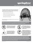
GENERAL PURPOSE THERMAL MASS FLOWMETERS TSI® SERIES 4000 / 4100 RS232 SERIAL COMMAND SET OPERATION AND SERVICE MANUAL P/N 1980340, REVISION J OCTOBER 2013 GENERAL PURPOSE THERMAL MASS FLOWMETERS TSI® SERIES 4000 / 4100 RS232 SERIAL COMMAND SET OPERATION AND SERVICE MANUAL P/N 1980340, REVISION J OCTOBER 2013 U.S. & INTERNATIONAL Sales and Customer Service: (800) 874-2811 / +1(651) 490-2811 Fax: +1(651) 490-3824 TSI Instruments Ltd. (UK) Sales and Customer Service: +44 (0) 1494 459200 Fax: +44 (0) 1494 459700 iii (This page intentionally left blank) iv Copyright TSI Incorporated / 2001-2013 / All rights reserved. Address TSI Incorporated, 500 Cardigan Road, Shoreview, MN 55126 USA WARNING TSI flowmeters employ a heated platinum sensor. They should not be used with flammable or explosive gasses or mixtures. Caution TSI flowmeters are not medical devices under FDA 510k and in no situation should they be utilized for human respiration measurements. LIMITATION OF WARRANTY AND LIABILITY (effective June 2011) (For country-specific terms and conditions outside of the USA, please visit www.tsi.com.) Seller warrants the goods sold hereunder, under normal use and service as described in the operator's manual, shall be free from defects in workmanship and material for 12 months, or if less, the length of time specified in the operator's manual, from the date of shipment to the customer. This warranty period is inclusive of any statutory warranty. This limited warranty is subject to the following exclusions and exceptions: a. Hot-wire or hot-film sensors used with research anemometers, and certain other components when indicated in specifications, are warranted for 90 days from the date of shipment; b. Pumps are warranted for hours of operation as set forth in product or operator’s manuals; c. Parts repaired or replaced as a result of repair services are warranted to be free from defects in workmanship and material, under normal use, for 90 days from the date of shipment; d. Seller does not provide any warranty on finished goods manufactured by others or on any fuses, batteries or other consumable materials. Only the original manufacturer's warranty applies; e. Unless specifically authorized in a separate writing by Seller, Seller makes no warranty with respect to, and shall have no liability in connection with, goods which are incorporated into other products or equipment, or which are modified by any person other than Seller. The foregoing is IN LIEU OF all other warranties and is subject to the LIMITATIONS stated herein. NO OTHER EXPRESS OR IMPLIED WARRANTY OF FITNESS FOR PARTICULAR PURPOSE OR MERCHANTABILITY IS MADE. WITH RESPECT TO SELLER’S BREACH OF THE IMPLIED WARRANTY AGAINST INFRINGEMENT, SAID WARRANTY IS LIMITED TO CLAIMS OF DIRECT INFRINGEMENT AND EXCLUDES CLAIMS OF CONTRIBUTORY OR INDUCED INFRINGEMENTS. BUYER’S EXCLUSIVE REMEDY SHALL BE THE RETURN OF THE PURCHASE PRICE DISCOUNTED FOR REASONABLE WEAR AND TEAR OR AT SELLER’S OPTION REPLACEMENT OF THE GOODS WITH NON-INFRINGING GOODS. TO THE EXTENT PERMITTED BY LAW, THE EXCLUSIVE REMEDY OF THE USER OR BUYER, AND THE LIMIT OF SELLER'S LIABILITY FOR ANY AND ALL LOSSES, INJURIES, OR DAMAGES CONCERNING THE GOODS (INCLUDING CLAIMS BASED ON CONTRACT, NEGLIGENCE, TORT, STRICT LIABILITY OR OTHERWISE) SHALL BE THE RETURN OF GOODS TO SELLER AND THE REFUND OF THE PURCHASE PRICE, OR, AT THE OPTION OF SELLER, THE REPAIR OR REPLACEMENT OF THE GOODS. IN THE CASE OF SOFTWARE, SELLER WILL REPAIR OR REPLACE DEFECTIVE SOFTWARE OR IF UNABLE TO DO SO, WILL REFUND THE PURCHASE PRICE OF THE SOFTWARE. IN NO EVENT SHALL SELLER BE LIABLE FOR LOST PROFITS OR ANY SPECIAL, CONSEQUENTIAL OR INCIDENTAL DAMAGES. SELLER SHALL NOT BE RESPONSIBLE FOR INSTALLATION, DISMANTLING OR REINSTALLATION COSTS OR CHARGES. No Action, regardless of form, may be brought against Seller more than 12 months after a cause of action has accrued. The v goods returned under warranty to Seller's factory shall be at Buyer's risk of loss, and will be returned, if at all, at Seller's risk of loss. Buyer and all users are deemed to have accepted this LIMITATION OF WARRANTY AND LIABILITY, which contains the complete and exclusive limited warranty of Seller. This LIMITATION OF WARRANTY AND LIABILITY may not be amended, modified or its terms waived, except by writing signed by an Officer of Seller. Service Policy Knowing that inoperative or defective instruments are as detrimental to TSI as they are to our customers, our service policy is designed to give prompt attention to any problems. If any malfunction is discovered, please contact your nearest sales office or representative, or call TSI's Customer Service department at (800) 874-2811 (USA) or (001 651) 490-2811 (International) or visit www.tsi.com. Trademarks TSI and TSI logo are registered trademarks of TSI Incorporated. vi CONTENTS CHAPTERS 1 FLOWMETER IDENTIFICATION ............................................... 1 2 CONNECTING PC TO FLOWMETER ....................................... 3 Flowmeter Interface .................................................................. 3 RS232 Configuration and Operation ........................................ 4 3 SERIAL INTERFACE PROTOCOL ............................................ 7 Data Format.............................................................................. 7 Buffering ................................................................................... 7 Command Format..................................................................... 7 4 COMMAND SET ......................................................................... 9 Command Set Summary .......................................................... 9 DmFTPnnnn ........................................................................... 11 Vmnnnn .................................................................................. 13 SSRnnnn ................................................................................ 15 SGn ........................................................................................ 15 SGMmm (Series 4000 only) ................................................... 15 SUn ......................................................................................... 16 SBTxnnn.nn (Series 4000) .................................................. 17 SBTxnn.nnn (Series 4100) .................................................. 17 SETxnnn.nn (Series 4000) ................................................... 18 SETxnn.nnn (Series 4100) ................................................... 18 CBT ........................................................................................ 18 CET ........................................................................................ 18 SASnnn .................................................................................. 19 SAZnnn ................................................................................... 19 SN ........................................................................................... 20 MN .......................................................................................... 20 REV ........................................................................................ 20 DATE ...................................................................................... 20 SURnnnn ................................................................................ 20 SDMm (Series 4100 Only) .................................................... 21 SDMFTPn (Series 4100 Only)............................................... 22 SDUn (Series 4100 Only) ....................................................... 23 Rxx ......................................................................................... 23 ? .............................................................................................. 24 DEFAULT ............................................................................... 24 SAVE ...................................................................................... 24 5 TROUBLESHOOTING ............................................................. 25 APPENDIXES A ERROR CODES ....................................................................... 27 B FACTORY DEFAULT PARAMETERS .................................... 29 vii (This page intentionally left blank) viii Chapter 1 Flowmeter Identification Figure 1-1 Series 4000 and 4100 Mass Flowmeters 1. On/Off Switch 2. Display 3. Mounting Inserts (2) 4. DC Power Input 5. Flow Inlet 6. Interface Connector and Optional Power Input 1 (This page intentionally left blank) 2 Chapter 1 Chapter 2 Connecting PC to Flowmeter Flowmeter Interface TSI offers an optional mini-DIN to 9-pin D-sub cable (TSI PN 1303583) for communicating through a standard computer RS232 serial port to the Series 4000 and 4100 mass flowmeters. An analog cable (TSI PN 1303584) with tinned leads is also available. The analog cable can be used to connect to the analog output of the flowmeter, as well as to supply power and connect to the RS232 bus. When using these cables, line up the arrow on the connector with the bottom side of the flowmeter. Flowmeter connector pin-out designations are shown below. Table 1. List of connector pin-outs and cable color code designations Pin 1 2 3 4 5 6 7 8 Function Power Input (+) Power Ground (-) Analog Output (+) Analog Ground (-) (no connection) RS232 Receive (in) RS232 Transmit (out) Logic Ground Cable color code for TSI Cable 1303584 Black Green Red Brown Blue White Yellow Gray 3 RS232 Configuration and Operation Many flowmeter operating parameters can be easily configured through the RS232 serial port. Likewise, the flow rate, temperature, pressure, and volume can be read through the serial port. RS232 Settings: Baud Rate Data Bits Parity Stop Bits Flow Control 38.4 k 8 None 1 None Table 4. Changeable Operating Parameters Function Select Gas Calibration (air, O2, N2, or N2O) Select Standard or Volumetric Flow Measurement LCD Display Update Rate (controls averaging) Select Measurement Display Scroll Mode Select Measurement Displayed on LCD Display Select Measurement Units on LCD Display Select Data Update Rate for Analog Output Set Analog Output Full-Scale Flow Rate Value Set Analog Output Zero Value Command SGn SUn SURnnnn SDMFTPn SDMm SDUn SSRnnnn SASnnn SAZnnn Configuration Software TSI has several software utilities to help you communicate with your flowmeter to change parameters and to obtain flow data. You can download the latest versions of these at no charge from our web site: http://flowmeters.tsi.com 1. If you only want to change one or more of the operating parameters shown in Table 4 (above), the easiest way is to use the software utility called “TSI setup”. This uses convenient pulldown menus to help change these parameters. After you have made your changes, be sure to click on “Send” to store the changes in the flowmeter’s memory. 4 Chapter 2 2. If you want to communicate directly with the flowmeter using the basic RS232 commands shown in the Serial Command Set Manual, you can use a terminal program. HyperTerminal is a common terminal program that is included with most versions of the Microsoft operating system. You can download a document from our web site that helps you configure HyperTerminal for use with TSI flowmeters. Download the document called “Using HyperTerminal to communicate with TSI Flowmeters”. 3. If you plan to develop a more sophisticated program for data collection and control using LabVIEW, you can download a demonstration program called “Real-time Demo Program” and the source code “Source Code for Real-time Demo Program”. This program is intended to be a basic demonstration program and not a practical laboratory tool. It does, however, have a convenient implementation of the VOLUME measurement function that can be useful for basic tests. Connecting PC to Flowmeter 5 (This page intentionally left blank) 6 Chapter 2 Chapter 3 Serial Interface Protocol Data Format The RS232 port settings are fixed in the Series 4000 / 4100 flowmeters as follows: Baud Rate ........ 38,400 Data Bits .......... 8 Parity ................ None Stop Bits ........... 1 Flow Control ..... None Buffering The flowmeters have an internal software buffer for both transmit and receive operations. Both buffers are 50 bytes long. Command Format The serial interface commands in this manual are designated by the bold font (ex. DmFTPnnnn). The commands are case sensitive. Upper case letters are used throughout the command set except as designated. The TSI Series 4000 / 4100 flowmeters use ASCII characters as the input command set. Each command sent to the flowmeter must be terminated by a carriage return (CR = 0x0d). Line feeds (LF = 0x0a ) are ignored. Select commands allow you to choose either ASCII or binary format for the returned data. Binary data transfers allow for faster operation. The Series 4000 / 4100 flowmeters allow some operating parameters to be stored in non-volatile memory to serve as the new power-on defaults (example: sample rate, gas calibration, etc). After selecting the new operating parameter value, initiate the SAVE command to permanently store this new value. If the SAVE command is not initiated, the change to the operating parameter will be lost when the flowmeter is turned off. The factory default operating parameters can always be reset by initiating the DEFAULT command. See Appendix B for a list of the factory default parameters. The Series 4000 / 4100 flowmeters send an acknowledge sequence to confirm that the command was received. For ASCII commands, the acknowledge sequence is “OK” CR LF. For binary commands, a single byte, 0x00, is returned. 7 (This page intentionally left blank) 8 Chapter 3 Chapter 4 Command Set Command Set Summary Commands for Flow Rate, Temperature, Pressure and Volume DmFTPnnnn Vmnnnn Returns flow rate, temperature, and pressure data at an interval equal to the sample rate. Returns a volume measurement by integrating flow rate over time. Measurement Setup Commands SBTxnnn.nn CBT CET Sets the begin-trigger level for starting data acquisition. Sets the end-trigger level for stopping data acquisition. Clears the begin-trigger level. Clears the end-trigger level. SSRnnnn SGn SGMmm SUn Sets the sample rate at which the data is returned. Sets the gas calibration to be used. Selects the air/oxygen mixture concentration. Selects either standard or volumetric units of flow. SETxnnn.nn Setup Commands for Analog Output SASnnn SAZnnn SSRnnnn Sets the full-scale flow rate of the analog output. Sets the zero intercept for the analog output. Sets the sample rate at which the analog output is averaged and updated. 9 Miscellaneous Commands Rxx SAVE DEFAULT SN MN REV DATE ? Reads the current values of the changeable operating parameters. Saves the current values of changeable operating parameters to nonvolatile memory. Restores the values of changeable operating parameters to factory default settings. Returns the serial number of the flowmeter. Returns the model number of the flowmeter. Returns the internal firmware revision of the flowmeter. Returns the date of the last calibration. Returns “OK” to tell if the flowmeter is communicating. Display Commands SURnnnn Sets the update rate for the LCD display. SDMm Sets the Display Mode (Series 4100 only) to continuously show on the display. SDMFTPn Sets Display Mode (Series 4100 only) to scroll the LCD display between flow, temperature, and pressure. SDUn Sets the flow measurement units (L/min or cm3/min) for the LCD display (Series 4100 only). 10 Chapter 4 DmFTPnnnn Returns Flow, Temperature, and Pressure data at an interval equal to the sample rate. The data is returned in the order of Flow, Temperature, and Pressure. All three measurements may be requested or a combination of the three as indicated below. D m F T P nnnn Denotes data transfer Denotes data format: A = ASCII, B = binary, C = ASCII followed by CR and LF Requests a flow reading (replace with lower case ‘x’ if a flow reading is not desired) Requests a temperature reading (replace with a lower case ‘x’ if a temperature reading is not desired) Requests a pressure reading (replace with a lower case ‘x’ if a pressure reading is not required) Denotes maximum number of samples to return, range is 1 to 1000. (‘0500’ denotes 500 readings, leading zeros must be included) Example 1) DAFxP0250 Requests 250 readings of flow and pressure data in ASCII format. Example 2) DBxTx1000 Requests 1000 readings of temperature in binary format. Flow data is returned in units of Std L/min or L/min (see SUn command). Temperature data is returned in units of °C. Pressure data is returned in units of kPa. Before initiating this command, the sample interval, gas calibration, and flow units should be set. The sample interval between data points is set using the SSRnnnn command. The gas calibration is set using the SGn command. The units of standard or volumetric flow is set using the SUn command. The data can be returned in either ASCII or binary. Command Set 11 If ASCII mode is chosen, the acknowledge sequence is “OK” CR LF. If the command generated an error, an error code “ERRn” CR LF will be returned where n represents an error code 0 through 9. See Appendix A for a list of possible error codes. The readings returned are separated by commas and the termination sequence is a CR LF. The Series 4000 sends 2 decimal places, and the Series 4100 sends 3 decimal places for flow rate. If binary mode is chosen, a single byte, 0x00, will be returned as a command acknowledgment. If a command generated an error, then a single byte will be returned in place of the acknowledgment byte. See Appendix A for a list of error codes. Each reading returns two bytes. The most significant byte is returned first. Flow rate data is returned as an unsigned integer (0 to 65535) that has been multiplied by 100 (for Series 4000) or by 1,000 (Series 4100). Temperature data is returned as a signed integer (-32768 to 32767) that has been multiplied by 100. Pressure data is returned as an unsigned integer that has been multiplied by 100. To convert the returned data back to its original form, divide the data by 100. Binary transfers terminate by returning two bytes in the form 0xff 0xff. Check the first reading in each block of data returned (flow, temperature, and pressure) from the unit, for the terminating sequence. No termination sequence will be sent if an error condition occurred. Special note: a temperature reading of –0.01 C would be transmitted as 0xff 0xff and could signal an early termination if flow readings were disabled. If no begin-trigger is set, the data acquisition begins immediately upon processing of the command. If a begin-trigger is set (set with SBTxnnn.nn), the data acquisition begins as soon as the begintrigger condition is detected. If no end-trigger is set, then nnnn samples will be used in the data set. If an end-trigger is set (set with SETxnnn.nn), then the acquisition will stop either when the endtrigger condition is detected or when nnnn samples have been acquired, whichever comes first. After the command is finished, a termination sequence is sent to signal the end of the transfer. Example 3) SSR0010 Set sample rate to one average sample every 10ms Flowmeter returns OK <CR> <LF> SG1 Use the oxygen gas calibration Flowmeter returns OK <CR> <LF> SBTF+001.00 Begin sample by triggering on increasing flow at 1.0 Std L/min Flowmeter returns OK <CR> <LF> DAFxx0005 Request 5 samples of flow in ASCII format. Flowmeter returns OK <CR> <LF> 12 Chapter 4 Flowmeter returns flow data as follows. 1.10,1.20,1.25,1.23,1.20<CR> <LF> Example 4) DBFxx0005 Request 5 samples of flow in binary format. An example of the data that could be returned is as follows. 0x00 0x33 0x09 0x33 0x1f 0x33 0x25 0x33 0x2d 0x33 0x2e 0xff 0xff After conversion, the data would look like: 130.65 130.87 130.93 131.01 131.02 Example 5) DCFTx0005 Request 5 samples of flow and temperature in ASCII format but with CR and LF following each data set. Returns data as follows. 1.10,23.45<CR> <LF> 1.20,23.53<CR> <LF> 1.25,23.48<CR> <LF> 1.23,23.39<CR> <LF> 1.20,23.50<CR> <LF> Vmnnnn Returns a volume measurement by integrating flow rate over time. V m nnnn Denotes volume measurement Denotes data format: A = ASCII, B = binary Denotes maximum number of flow samples to integrate, range is 1 to 9999 (‘0500’ denotes 500 readings, leading zeros must be included) Example 1) VA2000 Request a single volume reading by integrating a maximum of 2000 flow samples and return data in ASCII format. Volume data is returned in units of standard liters or volumetric liters (see SUn command). Before initiating this command, the sample interval, gas calibration, and volume units should be set. The sample interval between data points is set using the SSRnnnn command. The gas calibration is set using the SGn command. Command Set 13 The units of standard or volumetric is set using the SUn command. The most common units are volumetric liters. The data can be returned in either ASCII or binary. If ASCII mode is chosen, the acknowledge sequence is “OK” <CR>< LF>. If the command generated an error, instead of “OK” CR LF being returned an error code “ERRn” <CR> <LF> will be returned where n represents an error code 0 through 9. See Appendix A for a list of possible error codes. The termination sequence is a CR LF. If binary mode is chosen, the acknowledge sequence is a single byte 0x00. If the command generated an error, a single byte error code will be returned instead of 0x00. See Appendix A for a list of possible error codes. The reading is represented by 2 bytes. The most significant byte is returned first. The data is represented as an unsigned integer (0 to 65535) that has been multiplied by 100 (Series 4000) or by 1,000 (Series 4100). Therefore, you must divide the integer that is returned by 100 or 1000 to get the correct result. The termination sequence for binary is 0xff 0xff. If no begin-trigger is set, the data acquisition begins immediately upon processing of the command. If a begin-trigger is set (set with SBTxnnn.nn), the data acquisition begins as soon as the begintrigger condition is detected. If no end-trigger is set, then nnnn samples will be used in the integral. If an end-trigger is set (set with SETxnnn.nn), then the acquisition will stop either when the endtrigger condition is detected or when nnnn samples has been acquired which ever comes first. After the command is finished, a termination sequence is sent to signal the end of the transfer. Example 2) VA1000 Request volume measurement with at most 1000 samples, data returned in ASCII. Returns volume data as follows: OK <CR> <LF> 130.651 <CR> <LF> Example 3) VB1000 Request volume measurement with at most 1000 samples, data returned in binary. Returns data as follows: 0x00 0x33 0x09 0xff 0xff After conversion, the data would look like: 130.65 14 Chapter 4 SSRnnnn Sets the sample rate for data returned through the serial port and also controls the update rate of the linearized analog flow output. SSR nnnn Denotes set sample rate Denotes number of milliseconds per sample, range 1 to 1000. (‘0005’ denotes 5 milliseconds per sample, leading zeros must be included) Longer sample rates provide greater flow averaging, whereas shorter sample rates provide greater frequency response. After the command is processed, an acknowledge sequence of “OK” CR LF is sent. If the command generated an error, an error code of “ERRn” CR LF will be sent. See Appendix A for a list of possible error codes. Use the SAVE command to permanently store the selected sample rate as the new power-on default. SGn SGMmm (Series 4000 only) Sets the gas calibration to be used or sets the air/oxygen mixture concentration. Models 4040/4043/4045 Only SG n SGM mm Denotes set gas calibration Denotes the gas calibration desired; range is 0 to 6 0=Air, 1= 100% O2, 6= 100% N2, 2-5 are invalid in these models NOTE: N2 calibration is only implemented in these three models with serial numbers of 404xXXXXXXXX and higher Denotes set air/oxygen mixture concentration Denotes the amount of oxygen in air. Range is 21% to 99%. The display will indicate the current gas calibration, either air or O2. For air/oxygen mixtures, the display will indicate both air and oxygen. NOTE: The SGMmm command is implemented in all Model 4043 and 4045. It is only implemented in Model 4040 with serial numbers of 40409921001 and higher. Command Set 15 Models 4140 / 4143 Only SG Denotes set gas calibration n Denotes the gas calibration desired; range is 0, 1, 2, 6 0 = Air, 1 = 100% O2, 2 = 100% N20, 6 = 100% N2 The display will indicate the current gas calibration, either air, O2, N2, or N2O. NOTE: The nitrogen capability is implemented in model 4043, but only in model 4140 with serial numbers of 41400027006 and higher. After the command is processed, an acknowledge sequence of “OK” CR LF is sent. If the command generated an error, instead of “OK” CR LF being sent an error code of “ERRn” CR LF will be sent. See Appendix A for a list of possible error codes. Use the SAVE command to permanently store the selected gas calibration or air/oxygen mixture as the new power-on default. SUn Select either standard or volumetric units of flow for data displayed on the LCD display and for data received through the serial port. SU n Denotes whether flow is measured in standard units or volumetric units Denotes which units S = standard flow rate, V = volumetric flow rate The LCD display will indicate Std L/min when the flow is set to standard units. The display will indicate L/min when flow is set to volumetric. The Series 4100 flowmeters (only) can be set to display in either L/min or cm3/min (see SDUn command). These flowmeters can therefore be set to display “std cm3/min” or “cm3/min” by using the SUn command. The Series 4000 and 4100 flowmeters are designed to measure flow in units of standard L/min or cm3/min (Series 4100 only). When selecting volumetric flow rate, they perform a flow correction as shown below by measuring gas temperature and pressure. Flow output in volumetric L/min is less accurate due to additional 16 Chapter 4 uncertainties encountered when measuring gas temperature and pressure. The following equation is based on applications of the ideal gas law. 273.15 Tm 101.3 VolumetricFlow (StandardFlow ) 273.15 21.11 Pm After the command is processed, an acknowledge sequence of “OK” CR LF is sent. If the command generated an error, instead of “OK” CR LF being sent an error code of “ERRn” CR LF will be sent. See Appendix A for a list of possible error codes. Use the SAVE command to permanently store the selected flow units as the new power-on default. SBTxnnn.nn (Series 4000) SBTxnn.nnn (Series 4100) Sets the begin-trigger level for starting the data acquisition. SBT x nnn.nn Denotes set begin-trigger Denotes trigger source: F = flow, P = pressure Denotes positive or negative trigger: + = positive, - = negative Set trigger level (‘001.00’ would denote 1.00 Std L/min, leading and trailing zeros must be included) The set trigger level stays in effect until cleared using the CBT command. The trigger level is also cleared when the flowmeter is turned off or the DEFAULT command is initiated. After the command is processed, an acknowledge sequence of “OK” CR LF is sent. If the command generated an error, instead of “OK” CR LF being sent an error code of “ERRn” CR LF will be sent. See Appendix A for a list of possible error codes. Example 1) SBTF+002.00 Sets a begin-trigger level of 2.00 Std L/min with positive slope. Example 2) SBTP-110.00 Sets a begin-trigger level of 110.0 kPa with negative slope. Command Set 17 SETxnnn.nn (Series 4000) SETxnn.nnn (Series 4100) Sets the end-trigger level for stopping data acquisition. SET x nnn.nn Denotes set end-trigger Denotes trigger source: F = flow, P = pressure Denotes positive or negative trigger: + = positive, - = negative Sets trigger level (‘001.00’ would denote 1.00 Std L/min, leading zeros must be included) The set trigger level stays in effect until cleared using the CET command. The trigger level is also cleared when the flowmeter is turned off or the DEFAULT command is initiated. After the command is processed, an acknowledge sequence of “OK” CR LF is sent. If the command generated an error, instead of “OK” CR LF being sent an error code of “ERRn” CR LF will be sent. See Appendix A for a list of possible error codes. Example 1) SETF-002.00 Sets an end-trigger level of 2.00 Std L/min with negative slope. Example 2) SETP+110.00 Sets an end-trigger level of 110.0 kPa with positive slope. CBT Clears the begin-trigger level. Begin-trigger function is disabled. The flowmeter will return an acknowledge sequence of “OK” CR LF as a response. CET Clears the end-trigger level. End-trigger function is disabled. The flowmeter will return an acknowledge sequence of “OK” CR LF as a response. 18 Chapter 4 SASnnn Sets the full-scale flow rate scaling factor of the linearized analog output. SAS nnn Denotes set scaling factor Sets full-scale flow rate output. Range is 1 to full scale flow rating of the flowmeter (see Appendix B for factory default values). (‘010’ denotes 10 Std L/min, leading zeroes must be included) The linearized analog output can be configured for various full-scale flow rate values. This value can be changed to improve the resolution of the analog signal by narrowing the range of flow. After the command is processed, an acknowledge sequence of “OK” CR LF is sent. If the command generated an error, instead of “OK” CR LF being sent an error code of “ERRn” CR LF will be sent. See Appendix A for a list of possible error codes. Use the SAVE command to permanently store the new full-scale flow value as the new power-on default. SAZnnn Sets the zero intercept for the linearized analog output. SAZ nnn Denotes set analog zero intercept Denotes number of mV for the zero flow intercept. Range is –100 to 100mV. (leading zeros must be included) The zero intercept nnn is in units of mV. The factory default is 0 mV. If nnn = 010 then at zero flow, the analog output will be 10 mV. This command will accept a negative offset formatted as SAZ-nnn. The zero adjustment range is –100mV to 100mV. Note that this command sets the zero intercept only and is not a true “zero adjust”. The analog output cannot go negative. Use the SAVE command to permanently store the new zero intercept value as the new power-on default. Example 1) SAZ030 Sets zero intercept of zero flow to +30 mV Example 2) SAZ-050 Sets zero intercept of zero flow to –50 mV Note that the analog output cannot go negative. Command Set 19 SN Returns the serial number of the flowmeter in ASCII. The serial number is an alpha-numeric string terminated by a CR LF. The string can be a maximum of 16 characters in length plus the terminating CR LF. Example: 40409806004 MN Returns the model number of the flowmeter in ASCII. The model number is an alpha-numeric string terminated by a CR LF. The string can be a maximum of 12 characters in length plus the terminating CR LF. Example: 4040 REV Returns the internal firmware revision of the flowmeter in ASCII. The revision is an alpha-numeric string terminated by a CR LF. The string can be a maximum of 3 characters in length plus the terminating CR LF. Example: 1.3 DATE Returns the date of the last calibration in ASCII. The format of the string is ‘month/day/year’. The date is an alpha-numeric string terminated by a CR LF. The string can be a maximum of 8 characters in length plus the terminating CR LF. Example: 12/24/98 SURnnnn Sets the update rate for the LCD display. SUR nnnn Denotes the set update rate command Denotes the number of milliseconds per update. Range is 50 to 5000. (‘0050’ denotes 50 milliseconds per update, leading zeros must be included) Data displayed on the LCD is averaged based on the update rate. If the display rate were set to 1000 ms, the data shown on the display would be averaged for 1 second. This command affects only the LCD display. The update rate for the linearized analog output and the serial output is controlled through the SSRnnnn command. 20 Chapter 4 After the command is processed, an acknowledge sequence of “OK” CR LF is sent. If the command generated an error, instead of “OK” CR LF being sent an error code of “ERRn” CR LF will be sent. See Appendix A for a list of possible error codes. Use the SAVE command to permanently store the selected update rate as the new power-on default. SDMm (Series 4100 Only) Selects the measurement parameter that will be continuously shown on the LCD display. This command affects only the LCD display. SDM m Denotes set display mode Denotes measurement parameter that will be shown on the LCD display, where F = flow rate, T = temperature, and P = pressure Example 1) SDMT LCD will continuously display temperature. Example 2) SDMP LCD will continuously display pressure Use the SAVE command to permanently store the selected measurement parameter as the new power-on default. Command Set 21 SDMFTPn (Series 4100 Only) Sets the LCD display into a “scroll” mode, where the desired measurement parameters are alternately shown on the display. This command affects only the LCD display. SDM F T P n Denotes set display mode Denotes flow rate (replace with lower case “x” if a flow reading is not desired) Denotes temperature (replace with a lower case “x” if a temperature reading is not desired) Denotes pressure (replace with a lower case “x” if a pressure reading is not desired) Denotes the number of display update cycles that each parameter will be displayed. See the SUR command. If the update rate (SUR) is set to 500 milliseconds and “n” is set to 2, then each parameter will be displayed for two cycles, or 1.0 second. The display will then move to the next parameter and display it for 1.0 second, etc. The F-T-P elements of this command can be in any order and can be repeated, so long as the total number of elements is three. For example, SDMFFT2, SDMPTF2, SDMTTP2, SDMxPF2, and SDMPxF2 are all valid commands Example 1) SDMFTP2 (and SUR is set to 1000 ms) The display will alternate between flow, temperature, and pressure. Each parameter is displayed for 2 seconds (2 x 1000 ms). Example 2) SDMFxP3 (and SUR is set to 500 ms) The display will alternate between flow and pressure. Each parameter is displayed for 1.5 seconds (3 x 500 ms). Example 3) SDMFFT3 (and SUR is set to 500 ms) The display will show flow for 3 seconds (2 x 3 x 500 ms) and then show temperature for 1.5 seconds (3 x 500 ms). Use the SAVE command to permanently store the new Set Display Mode conditions as the new power-on default. 22 Chapter 4 SDUn (Series 4100 Only) Selects the flow measurement units that will be shown on the LCD display. LCD will indicate “L/min” or “cm3/min”, depending on selected units. This command affects only the LCD display. See also the SUn command SDU n Denotes set display units Denotes the flow measurement units. Values are 0 or 1, where 0 = L/min and 1 = cm3/min. Default value is 0 (L/min) Example 1) SDU1 LCD display will show flow rate in cm3/min and the “cm3/min” indicator will be shown on LCD. Use the SAVE command to permanently store the selected measurement parameter as the new power-on default. Rxx Reads the current values for sample rate, gas calibration, standard/volumetric flow units, trigger values, analog output scaling and display update rate. R xx Denotes read current values. xx=SR Denotes sample rate (returns 0 to 1000). xx=G Denotes gas calibration (returns 0 to 6 for gas calibration, returns M21 to M99 for air/O2 mixture concentrations). xx=U Denotes flow units (returns S or V). xx=BT Denotes begin-trigger value (returns xxnnn.nn). xx=ET Denotes end-trigger value (returns xxnnn.nn). xx=AS Denotes analog flow rate scaling factor (returns 1 to 300). xx=AZ Denotes analog zero intercept (returns –100 to 100). xx=UR Denotes display update rate (returns 50 to 5000). xx=DM Denotes display mode (returns mmmn), Series 4100 only. xx=DU Denotes display units (returns n), Series 4100 only. Returns current settings in ASCII format. Leading zeroes are not returned. After the command is processed, an acknowledge sequence of “OK” CR LF is sent followed by the data. If the command generated an error, Command Set 23 instead of “OK” CR LF being sent an error code of “ERRn” CR LF will be sent. See Appendix A for a list of possible error codes. ? This is a ping command used to tell if the flowmeter is communicating. The flowmeter will return an acknowledge sequence of “OK” CR LF as a response. The serial communications indicator will flash once on the LCD display to indicate that the command was received. DEFAULT Returns the values for sample rate, calibration gas/gas mixture, standard/volumetric flow units, display update rate, display mode, analog zero, and full-scale scaling factors to the factory default settings. To make these values the new power-on default, the SAVE command must be executed following the DEFAULT command. This command also clears both the begin- and end-trigger values. The default values for the Series 4000 / 4100 operating parameters are listed in Appendix B. SAVE Saves the current values for sample rate, calibration gas/gas mixture, standard/volumetric flow units, display update rate, display mode, analog zero, and scaling factors to the internal nonvolatile memory. The flowmeter will be restored to this configuration when powered on. The following parameters are saved: Sample Rate (SSRnnnn) Gas (SGn) Flow Units (SUn) Analog Full-Scale Flow Rate (SASnnn) Update Rate for LCD Display (SURnnnn) Default Measurement Parameter (SDMm) Default Set Display Mode Conditions (SDMFTPn) Default LCD Display Parameter (SDUn) After the command is processed, an acknowledge sequence of “OK” <CR><LF> is sent. If the command generated an error, an error code of “ERRn” <CR><LF> will be sent. See Appendix A for a list of possible error codes. 24 Chapter 4 Chapter 5 Troubleshooting Table 2 lists the symptoms, possible causes, and recommended solutions for common problems encountered with the flowmeter. If the symptom is not listed, or if none of the solutions solves the problem, please contact TSI Customer Support at 800-874-2811 or 651-4903811. Table 2. Troubleshooting Symptom Communication not working Possible Causes Selected wrong PC Comm port Corrective Action Review Comm port selection. Cable not connected See Chapter 2. Flowmeter not powered Turn on flowmeter. Serial communication parameters incorrectly set See Chapter 3. 25 Technical Contacts If you have any difficulty installing the Series 4000/4100, or if you have technical or application questions about this instrument, contact an applications engineer at TSI Incorporated, (651) 490-2811 or contact [email protected]. If the Series 4000/4100 fails, or if you are returning it for service, visit our website at http://rma.tsi.com or contact TSI at: TSI Incorporated 500 Cardigan Road Shoreview, MN 55126 USA Phone: +1-800-874-2811 (USA) or +1 (651) 490-2811 E-mail: [email protected] TSI GmbH Neuköllner Strasse 4 52068 Aachen GERMANY Telephone: Fax: E-mail: Web: +49 241-52303-0 +49 241-52303-49 [email protected] www.tsiinc.de TSI Instruments Ltd. Stirling Road Cressex Business Park High Wycombe, Bucks HP12 3ST UNITED KINGDOM Telephone: Fax: E-mail: Web: 26 +44 (0) 149 4 459200 +44 (0) 149 4 459700 [email protected] www.tsiinc.co.uk Chapter 5 Appendix A Error Codes 1 Unrecognizable command – The flowmeter uses the length of the command and the first few letters (how many letters depends on the command) to recognize a valid command. 2 Number out of range – The number entered as the operand to a command was out of the specified range or unrecognizable. 3 Invalid mode – One or more requested options to a command were invalid. 4 Command not possible – The supplied operands describe a command that is beyond the functional capability of the flowmeter. 8 Internal error – An internal failure was detected. 27 (This page intentionally left blank) 28 Appendix A Appendix B Factory Default Parameters Default factory parameter settings of the Series 4000 Flowmeters Sample Rate: Gas Calibration: Flow Units: Display Update Rate: Analog Output Scaling: Analog Zero Scaling: Triggers Disabled 10ms 0=Air Standard 500 ms 300 Std L/min for Models 4040/4045 200 Std L/min for Model 4043 0 mV Default factory parameter settings of the Series 4100 Flowmeters Sample Rate: Gas Calibration: Flow Units: Display Update Rate: Analog Output Scaling: Analog Zero Scaling: Triggers Disabled Display Mode 10ms 0=Air Standard 500 ms 20 Std L/min for Model 4140 0 mV Flow 29 TSI Incorporated – Visit our website www.tsi.com for more information. USA UK France Germany Tel: +1 800 874 2811 Tel: +44 149 4 459200 Tel: +33 4 91 11 87 64 Tel: +49 241 523030 P/N 1980340 Rev. J India Tel: +91 80 67877200 China Tel: +86 10 8219 7688 Singapore Tel: +65 6595 6388 ©2013 TSI Incorporated Printed in U.S.A.