1
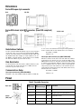
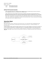
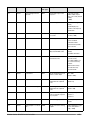
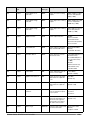
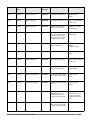
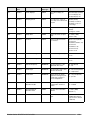
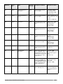
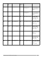
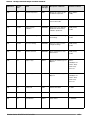
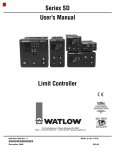
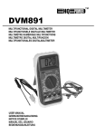
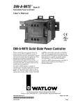
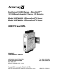
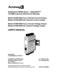
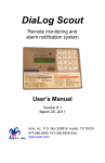
Series SD6 PID with DeviceNet (Addendum)
Watlow’s Series SD6 with DeviceNet offers excellent control and application flexibility in a 1/16th DIN panel
mount package.
The Series SD6 with DeviceNet has successfully passed
the rigorous testing requirements of ODVA and is also
SEMI-SIG compliant.
Keys and Display
Diagnostic Indicator Lights
Provide operating and diagnostic information about
the module (MOD) and network (NET).
SD6C-XXXA-DXXX shown.
Up and
Down Keys
In the Home
Page, adjusts
the set point.
This single-channel controller includes a universal sensor
input with two outputs that can be configured as heat,
cool, or alarm. The DeviceNet communications interface is
supplied with either of two standard connectors, a closed
style M12 (Semi-SIG compliant) or an open style connector.
The Series SD6 with DeviceNet is only available
with one or two outputs.
In other pages,
changes the
upper display
to a higher or
lower value.
Ordering Information and
Model Numbers
S D 6 __
Advance Key
Advances the lower display
through parameter prompts.
__ __ __ A - D __ __ __
Control Type
C = PID Control
L = Limit Control
R = Ramping
Power Supply
H = 100 to 240VÅ (ac)
L = 24 V‡ (ac/dc)
Table 1. Module Status (MOD) Indicator Light
Indicator Light
Description
Off
No power is applied to the device.
Flashing Green-Red
The device is performing a self-test.
Flashing Red
The controller is in Auto mode and an input
error condition [Er;in] exists. This indication
does not occur if the controller is in the
Manual mode when an input error occurs.
Red
A checksum error [Er;CS] has occurred.
Green
The device is operating normally.
Output 1
C = Switched dc
K = SSR, Form A, 0.5 A
F = Universal process
J = Mechanical relay, Form A, 2 A
Table 2. Network Status (NET) Indicator Light
Output 2
A = None
C = Switched dc
K = SSR, Form A, 0.5 A
J = Mechanical relay, Form A, 2 A
DeviceNet Communications
Indicator Light
Description
Off
The device is not online.
The device has not completed the duplicate MAC ID test yet.
The device may not be powered. Look at
Table 1, Module Status Indicator Light.
Green
The device is online and has connections
in the established state.
For a Group 2 Only device it means that
the device is allocated to a Master.
Red
Failed communication device.
The device has detected an error that has
rendered it incapable of communicating on
the network (duplicate MAC ID or Bus-off).
Flashing Green
The device is online, but no connection
has been allocated or an explicit connection has timed out.
Flashing Red
A poll connection has timed out.
N = Open style connector
S = Closed style M12 connector (Semi-SIG compliant)
Display Colors and Custom Options
RG = Red Green
RR = Red Red
XX = Custom options, special overlays, etc.
0600-0041-0015
Infinity Key
Returns to the
Home Page.
Rev D
June 2005
This document is available as an Adobe Acrobat PDF file at
www.watlow.com; search on “SD6 DeviceNet”.
Dimensions
Series SD6 open style connector
Back
Left Side
Series SD6 closed style M12 connector, (Semi-SIG compliant)
Back
Left Side
Switch Label
Node Address Switches
Set the controller’s MAC ID with the top two rotary switches
on the side of the case. Set the most significant digit (MSD)
with the top switch and the least significant digit (LSD) with
the middle switch. For example, to set the address to 23, set
the MSD to 2 and the LSD to 3. If the switch is set to“PGM”,
the last node address at power down is used.
Data Rate Switch
Set the Data Rate switch (below the address switches) to the
network data rate. If the switch is set to “PGM”, the last
baud rate at power down is used.
Communications Setup
(0 - 63) can be selected from the front panel (Setup Menu) or
via the software. The factory default values are as follows:
Baud Rate = 125KB
Address = 63
Closed style (M12 connector) only (SD6X-XXXA-DSXX)
The three switches on the side of the unit define the address
and baud rate (See picture above for closed style SD6). If the
MSD switch is in the "P" (Program) position, the address will
be software programmable. Likewise, if the Data Rate switch
is set to "PGM" the data rate will be software programmable.
On power down, the unit will always come back into the network with its last known baud rate and address. The factory
default values are as follows:
Baud Rate = 500KB
Open style connector only (SD6X-XXXA-DNXX)
Address = 63
Baud Rate (125, 250, 500KB) and Node Address or MAC ID
Pinout
Table 3. DeviceNet Connectors
Open style
Closed
(M12) style
Pin
Open style
Pin
M12 Closed style
Signal
Black
3
V-
Blue
5
CAN_L
Negative side of the DeviceNet bus
Grey (bare)
1
Drain
Shield interconnect
White
4
CAN_H
Positive side of the DeviceNet bus
Red
2
V+
Function
DeviceNet power return
DeviceNet power
DeviceNet Communications
This appendix describes the DeviceNet protocol as it is
implemented in the Series SD6 controller. It primarily
describes the objects and attributes accessible via the
DeviceNet protocol. It may be necessary to refer to the
DeviceNet specification as a compliment to the information
found here.
Addressing
All data is referenced based upon a four-part definition:
Node (MAC ID) + Class + Instance + Attribute.
Table 4. Four Components to an Address, with
Ranges
DeviceNet Overview
Node Address (MAC ID)
[0 to 63]
The SD6 controller supports the object-based modeling
used in the DeviceNet concepts. This product is configured
as a Group 2 Only Slave device using the Predefined
Master/Slave Connection Set.
Class ID
Instance ID
Attribute ID
[1 to 255]
[0 to 255]
[1 to 255]
There are two main categories of objects, DeviceNet
Objects and Application Objects. DeviceNet objects handle
what is necessary for networking and communications.
Application Objects have access to the SD6 controller's
parameters and data.
Data Types
The descriptions of attributes in the following sections
includes the data type for each. Table 5 lists and describes
these data types.
Table 5. Descriptions of Elementary Data Types
Data Type Name
Data Type Description
BOOL
Logical Boolean with values TRUE and FALSE
BYTE
Bit string — 8 bits
EPATH
DeviceNet path segments
INT
Signed 16-bit integer value
SHORT_STRING
Character string (1 byte per character, 1 byte length indicator)
UDINT
Unsigned 32-bit integer value
UINT
Unsigned 16-bit integer value
USINT
Unsigned 8-bit integer value
WORD
Bit string — 16 bits
Watlow Series SD6 PID with DeviceNet
■ 3 ■
Group 2 Only Server
Electronic Data Sheet (EDS)
A slave (server) device that is UCMM incapable and must
use the Predefined Master/Slave Connection Set to establish communications (at a minimum, the Predefined
Master/Slave Explicit Messaging Connection must be supported). A Group 2 Only device can transmit and receive
only those identifiers defined by the Predefined
Master/Slave Connection Set (reference DeviceNet Spec.,
Vol. 1, Sec. 2).
The EDS allows a configuration tool to automate the device
configuration process. The EDS specification provides an
open standard for device configuration and compatibility
among all DeviceNet products. (Refer to the DeviceNet
Specification, Vol. 1, Chapter 4). You can obtain a copy of
the EDS at www.watlow.com and search on keywords SD
EDS, request a copy by sending an e-mail to [email protected] or by calling an Application Engineer at
+1 (507) 494-5656 between 7 a.m. and 5 p.m. Central
Standard Time (CST).
Master/Slave Connections
The SD6 supports the Predefined Master/Slave Connection
Set (refer to DeviceNet Specification, Vol. 1, Sec. 7). The
general model calls for the utilization of an Explicit
Messaging Connection to manually create and configure
Connection Objects within each connection end-point. This
chapter uses the general model as a basis for the definition
of a set of connections that facilitate communications typically seen in a master-slave relationship. These
Connections are referred to collectively as the Predefined
Master/Slave Connection Set.
The master is the device that gathers and distributes I/O
data for the process controller. Slaves are the devices from
which the master gathers I/O data and to which the master distributes I/O data. The master “owns” the slaves
whose MAC IDs appear in its scan list. To determine with
what slaves it will communicate, the master examines its
scan list and sends commands accordingly. Except for the
Duplicate MAC ID Check, a slave cannot initiate any communication before being told by the master to do so.
DeviceNet Objects
The following sections describe the standard DeviceNet
objects and the SD6-specific application objects.
Identity Object
Class Code: 01hex
The Identity object provides identification information for
the device. This includes the device manufacturer, product
name, product type, serial number and revision.
Refer to the DeviceNet Specification (Vol. II, Sec. 6-2) for
complete requirements.
Status Attribute – This is a bit field that represents the
current status of the device. Two of the bits in the Status
attribute, the Minor Recoverable Fault and Major
Recoverable Fault bits, shall never be set. In accordance
with the semiconductor industry standard, all module level
faults are considered to be unrecoverable faults.
Table 6. Identity Object Revision History
Revision
Description
01
Initial Release
Table 7. Identity Object Class Attributes
Number
Access
Rule
Namer
Watlow Series SD6 PID with DeviceNet
Name
DeviceNet Data Type
Description of
Attribute
Semantics of
Values
■ 4 ■
Table 8. Identity Object Instance Attributes
Attribute #
Access Rule
Name
DeviceNet Data
Type
Description of
Attribute
Semantics of
Values
1
Get
Vendor ID
UNIT
Identification of each
vendor by number.
This is Vendor ID
153.
See “Semantics”
DeviceNet Spec, Vol.
II, Sec. 6-2.2
2
Get
Product Type
UNIT
Identification of general type of product.
This is Type 0.
See “Semantics”
DeviceNet Spec, Vol.
II, Sec. 6-2.2
3
Get
Product Code
UNIT
WATLOW SD6-DN,
CODE IS 105
See “Semantics”
DeviceNet Spec, Vol.
II, Sec. 6-2.2
WATLOW SD6-DS,
CODE IS 104
4
Get
Revision
STRUCT of:
Revision of the item
the Identity Object
represents
See “Semantics”
DeviceNet Spec, Vol.
II, Sec. 6-2.2
5
Get
Status
WORD
Summary status of
device
See “Semantics”
DeviceNet Spec, Vol.
II, Sec. 6-2.2
6
Get
Serial Number
UDINT
Serial number of
device
See “Semantics”
DeviceNet Spec, Vol.
II, Sec. 6-2.2
Set in accordance
with a Watlow manufacturing guidelines.
7
Get
Product Name
SHORT_STRING
Class Services: NONE
Instance Services:
• RESET (O,1)
GET ATTRIBUTE SINGLE
DeviceNet Object
Class Code: 03hex
The DeviceNet Object is used to provide the configuration
and status of a physical attachment to DeviceNet.
The MACID attribute provides the network address for the
device. If the rotary switches used to specify the device
MACID are set to a valid MACID, i.e. a value from 0 to 63,
the MACID attribute shall have Get Only access. If the
rotary switches are set to the programmable mode, the
MACID attribute shall have Get and Set access.
The Baud Rate attribute specifies the data rate for the
device. If the rotary switch used to set the data rate specifies a valid data rate, i.e. 125, 250, or 500K Baud, the Baud
Rate attribute shall have Get Only access. If the rotary
switches are set to the software programmable mode, the
MACID shall have Get and Set access.
Watlow Series SD6 PID with DeviceNet
Human readable ID:
“Watlow Series SD6”
See “Semantics”
DeviceNet Spec, Vol.
II, Sec. 6-2.2
The Allocate Master/Slave Connection Set service of the
DeviceNet object shall be a required service for all devices.
This implies a requirement that all devices are Group 2
devices on the DeviceNet network. Additionally, all devices
shall support, as a minimum, the Explicit connection and
the I/O Poll connection in the Master/Slave connection set.
The Release Master/Slave Connection Set service of the
DeviceNet object shall be a required service.
Refer to the DeviceNet Specification (Vol. I, Sec. 5-5) for
complete requirements.
Table 9. DeviceNet Object Revision History
Revision
Description
01
Initial Release
02
Modification of Baud Rate Attribute
Behavior
■ 5 ■
Table 10. DeviceNet Object Class Attributes
Attribute #
Access
Rule
Name
DeviceNet Data
Type
Description of
Attribute
Semantics of Values
1
Get
Revision
UINT
Revision of this object
The revision level of this
object. This is now at 2.
Table 11. DeviceNet Object Instance Attributes
Attribute #
Access Rule
Name
DeviceNet Data
Type
Description of
Attribute
Semantics of
Values
1
Get/Set*
MACID
USINT
Node Address
Range 0.. 63
2
Get/Set*
Baud Rate
USINT
Baud Rate
Range 0.. 2
4
Get
Bus-Off Counter
USINT
Number of times CAN
went to the bus-off
state
Range 0.. 255
5
Get
Allocation Information
STRUCT of:
Range 0.. 63, 255
Allocation Choice
Byte
BYTE
See Vol. I,
Section 5-5.4.2.
MAC ID of Master
(from Allocate)
Modified via Allocate
only
USINT
Master’s MAC ID
An input will produce data on the network and an output
will consume data from the network.
Class Services: GET ATTRIBUTE SINGLE
Instance Services: *SET ATTRIBUTE SINGLE (when
MACID or BAUD RATE in PRG MODE), GET
ATTRIBUTE SINGLE, ALLOCATE M/S CONNECTION
SET, RELEASE M/S CONNECTION SET.
The term “Static” implies: assemblies with member lists
defined by the device profile or by the manufacturer of the
product. The Instance number, number of Members, and
member list are fixed.
Assembly Object – “Static”
Table 12. Assembly Object Revision History
Class Code: 04hex
The Assembly Object binds attributes of multiple objects,
which allows data to or from each object to be sent or
received over a single connection. Assembly objects can be
used to bind input data or output data. The terms “input”
and “output” are defined from the network’s point of view.
Revision
Description
01
Initial Release
02
Class-specific Service Code 4B
and 4C obsolete
Table 13. Assembly Object Instance Attributes
Attribute #
Access Rule
Name
DeviceNet Data
Type
Description of
Instance
Semantics of
Values
3
Get/Set
Data
Array of BYTES
See description
below
See description
below
Instance #
Access Rule
Name
DeviceNet Data
Type
Description of
Instance
Semantics of
Values
100
Get/Set
Poll Output
LONG + USINT
Poll Output
See Poll output in
section 6.2.4
101
Get
Poll Input
USINT + LONG +
USINT + USINT
Poll Input
See Poll input in
section 6.2.4
Watlow Series SD6 PID with DeviceNet
■ 6 ■
Poll Connection
The poll connection allows the master to write set point and process value in one connection. It also allows the reading of
all process value, set point and alarm status.
Table 14. Static Input – Instance 101 in the Assembly Object - 7 bytes
Byte(s)
Parameter and Description
Size of Data
Range
0
Exception Status Byte - Byte
reserved for future use.
USINT
Always returns a value of
zero.
1-4
Process Value- Actual value of
process input
DINT
-1999.000 to 9999.000
5
Alarm Status - Indicates when USINT
alarm outputs are in alarm condition.
For each bit:
Breakdown of byte:
Bit 0: alarm low 1 status
Bit 1: alarm high 1 status
Bit 2: alarm low 2 status
Bit 3: alarm high 2 status
Bit 4 to bit 7: unused
(1) Alarm
6
Control Mode -
USINT
Breakdown of byte:
Bit 0: monitor the auto / manual status.
Bit 1 to bit 7: unused
(0) None
(0) Auto mode
(1) Manual mode
Table 15. Static Output – Instance 100 in the Assembly Object - 5 bytes
Byte(s)
Parameter and Description
Size of Data
0-3
Closed Loop Set Point - Control DINT
set point used in the auto mode
4
Control Modes Breakdown of byte:
Range
-1999.000 to 9999.000
USINT
Bit 0: Selects whether the
controller is in the auto or
manual mode.
(0) Auto mode
Bit 1: Selects whether the set
point adjustment is done via
the SD front panel or
through DeviceNet
(0) DeviceNet
Bit 2: Selects whether
Auto/Manual mode selection
is done via the SD front
panel or through DeviceNet.
(0) DeviceNet
Bit 3 to Bit 7: Not used
N/A
Watlow Series SD6 PID with DeviceNet
(1) Manual mode
(1) SD front panel
(1) SD front panel
■ 7 ■
Class Services: NONE
Instance Services:
• 0x0E
GET ATTRIBUTE SINGLE
• 0x10
SET ATTRIBUTE SINGLE
Additional Poll Connection information:
• In the event of the input error, a valid process value reading is no longer available. The poll connection will return a
value of 9999.999 for the process value while the error condition exists.
• Bit 1 and bit 2 of byte 4 in the output poll connection select whether set point and auto / manual mode values are
changed from the SD’s front panel or else over DeviceNet through the poll connection. Setting the bit to “zero” will relinquish control of the parameter to the DeviceNet master device (typically the master is a PLC). Setting the bit to “one” will
retain control of the parameter locally at the front panel of the Series SD controller. If there is a loss of communications,
control of auto / manual mode and adjustment of set point will automatically return to the Series SD front panel regardless
of the settings of byte 4 in the output poll connection.
Connection Object
Class Code: 05hex
The Connection Class allocates and manages the internal resources associated with both I/O and Explicit Messaging
Connections. The specific instance generated by the Connection Class is referred to as a Connection Instance or a
Connection Object.
A Connection Object within a particular module actually represents one of the end-points of a Connection. It is possible for
one of the Connection end-points to be configured and “active” (e.g., transmitting) without the other end-point(s) being
present. Connection Objects are used to model the communication specific characteristics of a particular application-toapplication relationship. A specific Connection Object Instance manages the communication-specific aspects related to an
end-point.
Watlow Series SD6 PID with DeviceNet
■ 8 ■
Explicit Connection
The Explicit Connection Object defines the configuration for the Explicit connection to the device. The Explicit Connection
object is an instance of the Connection Object defined in the DeviceNet Specification. All devices that are compliant with
the DeviceNet Specification must support at least one instance of the Connection object with a connection type of Explicit.
I/O Connection
I/O Connection objects define the configuration for the I/O connections to the device. Each I/O Connection object is an
instance of the Connection object defined in the DeviceNet Specification. All devices must be Group 2 devices and must support, as a minimum, the I/O Poll connection in the Master/Slave connection set.
Watchdog Timeout Action Attribute defines the action performed by the I/O Connection object in the event the
Inactivity/watchdog Timer for the connection expires. For the I/O Connection object, Auto Reset shall be an invalid value
for the Watchdog Timeout Action attribute. (ref. SIG Specification sec. 4.1.5.1.1)
Produced Connection Path Attribute defines the Application object class, instance, and attribute that produces data
over the I/O connection. For all I/O connections, the Produced Connection Path shall be a Logical Segment, as defined in
the DeviceNet Specification, and shall point to the Data Attribute of an Assembly object. The behavior of the device shall
be such that, if the Produced Connection Path attribute is modified, the Produced Connection Size Attribute shall be
modified internally to accurately reflect the size of the assembly produce by the I/O connection. For all I/O connection
objects in the Master/Slave Connection Set, if the Produced Connection Path attribute is modified, the new attribute value
shall be saved in Non-Volatile (NV) memory and shall be the default value when the connection is allocated. (ref. SIG
Specification sec. 4.1.5.1.2).
Produced Connection Size Attribute specifies the maximum number of data bytes produced over the I/O connection.
The Produced Connection Size attribute shall have Get Only access for all I/O connection objects. The Produced Connection
Size attribute shall accurately reflect the size of the assembly produced over the I/O connection. (ref. SIG Specification sec.
4.1.5.1.3).
Consumed Connection Path Attribute defines the Application object class, instance, and, optionally, attribute that consumes data received over the I/O connection. For all I/O connections over which the device is the Server (as specified by the
Direction field of the Transport Class Trigger attribute), then special requirements as defined in the Semi SIG specification
shall be followed. (ref. SIG Specification sec. 4.1.5.1.4)
Consumed Connection Size Attribute specifies the maximum number of data bytes consumed by the I/O connection
objects. The Consumed Connection Size attribute shall accurately reflect the size of the assembly consumed by the I/O connection, as specified by the Consumed Connection Path attribute of the Data With ACK Path List attribute of the
Acknowledge Handler object. (ref. SIG Specification sec. 4.1.5.1.5)
Refer to the Semi SIG specification (Sec. 4.1.4/5) for Semi requirements.
Refer to the DeviceNet Specification (Vol. II, Sec. 6-3) for complete requirements.
Table 16. Connection Object Revision History
Revision
Description
01
Initial Release
Table 17. Connection Object Class Attributes
Attribute #
Access
Rule
Name
Watlow Series SD6 PID with DeviceNet
DeviceNet Data
Type
Description of
Attribute
Semantics of Values
■ 9 ■
Table 18. Connection Object Instance Attributes
Attribute
#
Access
Rule
Name
DeviceNet
Data Type
Description of Attribute
1
Get
State
USINT
State of the object
2
Get
Instance Type
USINT
Indicates either I/O or Messaging
3
Get
Transport Class
Trigger
BYTE
Defines behavior of the Connection
4
Get
Produced
Connection ID
UINT
Placed in CAN Identifier Field when
the Connection transmits
5
Get
Consumed
Connection ID
UINT
CAN Identifier Field value that
denotes message to be received
6
Get
Initial Comm
Characteristics
BYTE
Defines the Message Group(s)
across which productions and consumption associated with this
Connection when it occurs
7
Get
Produced
Connection Size
UNIT
Maximum number of bytes transmitted across this Connection
8
Get
Consumed
Connection Size
UNIT
Maximum number of bytes received
across this Connection
9
Get/Set
Expected Packet
Rate
UNIT
Will round up to the next 100 mSec.
Increment.
12
Get/Set
Watchdog Timeout
Action
USINT
Defines how to handle
Inactivity/Watchdog timeouts
13
Get
Produced
Connection Path
Length
UINT
Number of bytes in the Produced
Connection Path Attribute
14
Get
Produced
Connection Path
EPATH
Specifies the Application Object(s)
whose data is to be produced by this
Connection Object. See Appendix I,
DeviceNet Specification
15
Get
Consumed
Connection Path
Length
UINT
Number of bytes in the Consumed
Connection Path Length
16
Get
Consumed
Connection Path
EPATH
Specifies the Application Object(s)
that are to receive data consumed
by this Connection Object. See
Appendix I, DeviceNet Specification
Watlow Series SD6 PID with DeviceNet
Semantics of
Values
For Explicit
Connection only:
1 = Auto Delete
3 = Deferred Delete
■ 10 ■
Class Services: NONE
Home Object
Instance Services:
Class Code: 64hex
•
0x0E
GET ATTRIBUTE SINGLE
•
0x10
SET ATTRIBUTE SINGLE
The Home Object provides access to parameters used for
the default display of the Series SD6.
•
0x05
RESET SERVICE
Table 19. Home Object Revision History
Revision
Description
01
Initial Release
Table 20. Home Object Class Attributes
Attribute #
Access
Rule
Name
DeviceNet Data
Type
Description of
Attribute
Semantics of Values
1
Get
Revision
UINT
Revision of this object
The revision level of
this object (currently 1)
2
Get
Max Instance
UINT
Max allowed
Instances of this
object
Always 1 for this Class
Watlow Series SD6 PID with DeviceNet
■ 11 ■
Table 21. Home Object Instance Attributes
Attribute #
Access
Rule
Name
DeviceNet
Data Type
Description of Attribute
Semantics of
Values
100
Get
Process Value
DINT
Current process value
-1999 to 9999
(*1000), °C or units
101
Get/Set
Closed Loop Set
Point
DINT
Current closed loop set point
Range is from set
point low limit to set
point high limit
102
Get
Filtered Process
Value
DINT
Filtered process value
-1999 to 9999
(*1000), °C or units
103
Get/Set
Open Loop Output
Power
INT
Current open loop output power (used
in manual mode)
-100.0 to 0.0% (*100)
if any output is set to
cool; 0.0 to 100.0%
(*100) if any output is
set to heat
104
Get
Current Ramp Set
Point
DINT
Current working control set point for
the ramp that is in process
-1999 to 9999
(*1000), °C or units
106
Get
Input Error
UINT
There is an analog input error
(0)
(1)
No error
Error
107
Get
Alarm Low 1 Status
BOOLEAN
There is an alarm 1 low side alarm
(0)
(1)
None
Alarm
108
Get
Alarm High 1 Status
BOOLEAN
There is an alarm 1 high side alarm
(0)
(1)
None
Alarm
109
Get
Alarm Low 2 Status
BOOLEAN
There is an alarm 2 low side alarm
(0)
(1)
None
Alarm
110
Get
Alarm High 2 Status
BOOLEAN
There is an alarm 2 high side alarm
(0)
(1)
None
Alarm
Class Services:
•
0x0E
Setup Object
GET ATTRIBUTE SINGLE
Instance Services:
•
0x0E
GET ATTRIBUTE SINGLE
•
0x10
SET ATTRIBUTE SINGLE
NOTE: All successful Explicit Message Responses from
a SET service will contain no data. The response will
be a two-byte message containing the requester’s MAC
ID and Service Code (with R/R bit set).
Watlow Series SD6 PID with DeviceNet
Class Code: 65hex
The Setup Object provides access to parameters that define
controller functions.
Table 22. Setup Object Revision History
Revision
Description
01
Initial Release
■ 12 ■
Table 23. Setup Object Class Attributes
Attribute #
Access
Rule
Name
DeviceNet Data
Type
Description of
Attribute
Semantics of Values
1
Get
Revision
UINT
Revision of this object
The revision level of
this object (currently 1)
2
Get
Max Instance
UINT
Max allowed
Instances of this
object
1 for this Class
Table 24. Setup Object Instance Attributes
Attribute #
Access
Rule
Name
DeviceNet
Data Type
Description of Attribute
Semantics of
Values
100
Get/Set
Sensor Type
USINT
Analog input sensor type
(0)
(1)
(2)
(3)
Thermocouple
(default)
RTD
MA
VOLT
101
Get/Set
Thermocouple
Linearization
USINT
Thermocouple Type
(0)
(1)
(2)
(3)
(4)
(5)
(6)
(7)
(8)
(9)
(10)
J
K (default)
T
E
N
C
D
PTII
R
S
B
102
Get/Set
Temperature Units
USINT
Temperature Units
(0)
(1)
°F
°C (default)
103
Get/Set
Temperature Decimal
Places
USINT
Thermocouple/RTD precision
(0)
(1)
0 (default)
0.0
104
Get/Set
Process Decimal
Places
USINT
Process precision
(0)
(1)
(2)
(3)
0 (default)
0.0
0.00
0.000
105
Get/Set
InfoSenseTM
USINT
Enables the sensor feature, which synchronizes the controller with a Watlow
sensor
(0)
(1)
NO (default)
YES
106
Get/Set
InfoSenseTM 1
UINT
Set sensor point 1 code
0 to 999
(default is 500)
107
Get/Set
InfoSenseTM 2
UINT
Set sensor point 2 code
0 to 999
(default is 500)
108
Get/Set
InfoSenseTM 3
UINT
Set sensor point 3 code
0 to 999
(default is 500)
Watlow Series SD6 PID with DeviceNet
■ 13 ■
Attribute #
Access
Rule
Name
DeviceNet
Data Type
Description of Attribute
Semantics of Values
109
Get/Set
InfoSenseTM 4
UINT
Set sensor point 4 code
0 to 999
(default is 500)
110
Get/Set
Process Scale Low mA
UDINT
Set the low scale for process input
0.00 to 20.00 mA
(* 1000) (when Sensor
Type set to mA, default
= 4.00 mA)
111
Get/Set
Process Scale Low
Volts
UDINT
Set the low scale for process input
0.0 to 10.00 V
(* 1000)
(when Sensor Type set
to Volt, default = 0.00 V)
112
Get/Set
Process Scale High mA
UDINT
Set the high scale for process input
0.00 to 20.00 mA
(* 1000) (when Sensor
Type set to mA, default
= 20.00 mA)
113
Get/Set
Process Scale High
Volts
UDINT
Set the high scale for process input
0.0 to 10.00 V
(* 1000)
(when Sensor Type set
to Volt, default = 0.00 V)
114
Get/Set
Units Scale Low
DINT
Set the low range for process input units
-1999 to 9999 (* 1000)
(default = -1999)
115
Get/Set
Units Scale High
DINT
Set the high range for process input
units
-1999 to 9999 (* 1000)
(default = 9999)
116
Get/Set
Set Point Low Limit
Thermocouple
DINT
Set the low range for the set point
Minimum operating
range (of sensor) to Set
Point High Limit – 0.001
(if Sensor Type =
Thermocouple, default =
min. for KThermocouple) (* 1000)
117
Get/Set
Set Point Low Limit
RTD
DINT
Set the low range for the set point
-328 to Set Point High
Limit – 0.001 (if Sensor
Type = RTD, default = 328)
(* 1000)
118
Get/Set
Set Point Low Limit mA
and volts
DINT
Set the low range for the set point
-1999 to Set Point High
Limit – 0.001 (if Sensor
Type = V or mA,
default = -1999)
(* 1000)
119
Get/Set
Set Point High Limit
Thermocouple
DINT
Set the high range for the set point
Units Scale Low to
max operating range of
sensor, if Input Type =
Thermocouple (default
= max operating range
for K-Thermocouple) (*
1000)
120
Get/Set
Set Point High Limit
RTD
DINT
Set the high range for the set point
Set Point Low Limit +
0.001 to 1472, if Input
Type = RTD (default =
1472) (* 1000)
Watlow Series SD6 PID with DeviceNet
■ 14 ■
Attribute #
Access Rule
Name
DeviceNet
Data Type
Description of Attribute
Semantics of Values
121
Get/Set
Set Point High Limit mA
and volts
DINT
Set the high range for the
set point
Set Point Low Limit +
0.001 to 9999, if Input
Type = mA or Volt (default
= 9999)
(* 1000)
122
Get/Set
Input Filter
USINT
Select filtering action
(1) OFF (no filtering,
default)
(1) Filter display only
(2) Filter control input only
(3) Filter both
123
Get/Set
Filter Value
UDINT
Set the input filter value, units
in seconds
0.0 to 60.0 (default = 0.0)
seconds (* 1000)
124
Get/Set
Output 1 Function
USINT
Set the output 1 function
(0) OFF
(1) Process Alarm
(2) Deviation Alarm
(3) Heat Control (default)
(4) Cool Control
125
Get/Set
Control Method 1
USINT
Set the output 1 control type
Only used with PID control
(1) Fixed Timed Base
(default)
(1) Variable Time Base
126
Get/Set
Fixed Time Base 1
USINT
Set the time base for fixed
time based control
1.0 to 60.0 if Output 1 is a
mechanical relay
0.1 to 60.0 if Output 1 is
not a mechanical relay
Defaults:
20.0 mechanical relay
5.0 solid-state relay
1.0 switched DC
127
Get/Set
Power Limit 1
UINT
Set the maximum power output for a control output
0.0 to 100%
(default = 100%)
128
Get/Set
Output Power Scale Low 1
USINT
Set the low end of the range
within which the output will
scale
0 to 100%
(default = 0)
129
Get/Set
Output Power Scale High 1
USINT
Set the high end of the range
within which the output will
scale
0 to 100%
(default = 100)
130
Get/Set
Output Non-linear Function
1
USINT
Select a non-linear output
curve to match the response
of your system
(0) OFF (default)
(1) Curve 1
(2) Curve 2
131
Get/Set
Analog Output 1 Units
USINT
Set the analog output units
(0) Milliamperes (default)
(1) Volts
132
Get/Set
Analog Output 1 Low Scale
mA
UDINT
Set the low scale for analog
outputs
0.00 to 20.00 mA if output
is set to mA (default =
0.00) (* 1000)
Watlow Series SD6 PID with DeviceNet
■ 15 ■
Attribute #
Access
Rule
Name
DeviceNet
Data Type
Description of Attribute
Semantics of Values
133
Get/Set
Analog Output 1 Low
Scale volts
UDINT
Set the low scale for analog
outputs
0.00 to 10.00 V if output
is set to Volts (default =
0.00) (* 1000)
134
Get/Set
Analog Output 1 High
Scale mA
UDINT
Set the high scale for analog
outputs
0.00 to 20.00 mA if output
is set to mA (default =
20.00 mA) (* 1000)
135
Get/Set
Analog Output 1 High
Scale volts
UDINT
Set the high scale for analog
outputs
0.0 to 10.00 V if output is
set to Volts (default =
10.00 V) (* 1000)
136
Get/Set
Output 2 Function
USINT
Set the output 2 function
(0) OFF
(1) Process Alarm
(2) Deviation Alarm
(3) Heat Control (default)
(4) Cool Control
137
Get/Set
Control Method 2
USINT
Set the output 2 control type
Only used with PID control
(0) Fixed Timed Base
(default)
(1) Variable Time Base
138
Get/Set
Fixed Time Base 2
UDINT
Set the time base for fixed
time based control
1.0 to 60.0 if Output 2 is a
mechanical relay
0.1 to 60.0 if Output 2 is
not a mechanical relay
(* 1000)
Defaults:
20.0 mechanical relay
5.0 solid-state relay
1.0 switched DC
139
Get/Set
Power Limit 2
UINT
Set the maximum power output for a control output.
1.0 to 100.0%
(default = 100.0%)
140
Get/Set
Output Power Scale Low
2
UINT
Set the low end of the range
within which the output will
scale.
0 to 100%
(default = 0)
141
Get/Set
Output Power Scale High
2
UINT
Set the high end of the range
within which the output will
scale.
0 to 100%
(default = 100)
142
Get/Set
Output Non-linear
Function 2
USINT
Select a non-linear output
curve to match the response
of your system.
(0) OFF (default)
(1) Curve 1
(2) Curve 2
143
Get/Set
Alarm 1 Hysteresis
UDINT
Set the hysteresis for an
alarm. This determines how
far into the safe region the
input needs to move before
the alarm can be cleared.
1.0 to 999.0 (* 1000)
(default = 1.0)
144
Get/Set
Alarm 1 Logic
BOOLEAN
Select the alarm output condition in the alarm state.
(0) Closed on alarm
(default)
(1) Open on alarm
Watlow Series SD6 PID with DeviceNet
■ 16 ■
Attribute #
Access
Rule
Name
DeviceNet
Data Type
Description of Attribute
Semantics of Values
145
Get/Set
Alarm 1 Latching
BOOLEAN
Turn alarm latching on or off.
(0) OFF (default)
(1) ON
146
Get/Set
Alarm 1 Silencing
BOOLEAN
Turn alarm silencing on or off.
(0) No silencing (default)
(1) Silencing
147
Get/Set
Alarm 1 Message
BOOLEAN
Display an alarm message
when an alarm is active.
(0) OFF (no message)
(1) ON (default)
148
Get/Set
Alarm 2 Hysteresis
UDINT
Set the hysteresis for an
alarm. This determines how
far into the safe region the
input needs to move before
the alarm can be cleared.
1.0 to 999.0 (* 1000)
(default = 1.0)
149
Get/Set
Alarm 2 Logic
BOOLEAN
Select the alarm output condition in the alarm state.
(0) Closed on alarm
(default)
(1) Open on alarm
150
Get/Set
Alarm 2 Latching
BOOLEAN
Turn alarm latching on or off.
(0) OFF (default)
(1) ON
151
Get/Set
Alarm 2 Silencing
BOOLEAN
Turn alarm silencing on or
off.
(0) No silencing (default)
(1) Silencing
152
Get/Set
Alarm 2 Message
BOOLEAN
Display an alarm message
when an alarm is active.
(0) OFF (no message)
(1) ON (default)
153
Get/Set
Units of Measurement
BOOLEAN
Set the type of units used for
the PID control parameters.
(0) US (default)
(1) SI
154
Get/Set
Input Error Latching
BOOLEAN
Turn the input error latching
on or off.
(0) OFF (default)
(1) ON
155
Get/Set
Input Error Failure Mode
USINT
Set the input error failure
mode when an error is
detected and the control
changes to manual mode.
(0) OFF (0% power)
(1) Bumpless (current
power level, default)
(2) Manual (fixed power
level)
156
Get/Set
Input Error Power
INT
Set the manual power level
when an input error causes
a change to manual mode.
-100.0 to 100.0%
Watlow Series SD6 PID with DeviceNet
■ 17 ■
Attribute #
Access
Rule
Name
DeviceNet
Data Type
Description of Attribute
Semantics of Values
157
Get/Set
Active Displays
USINT
Select which display are
active.
(0) Both displays (default)
(1) Lower display only
(2) Upper display only
158
Get/Set
Ramping Mode
USINT
Select when the control set
point ramps to the defined end
set point.
(0) OFF (default)
(1) Ramps on start-up
(2) Ramps on any set
point change
159
Get/Set
Ramp Scale
BOOLEAN
Select the scale of the ramp
rate.
(0) Degrees / hour
(default)
(1) Degrees / minute
160
Get/Set
Ramp Rate
UDINT
Set the rate for the set point
ramp.
0 to 9999 (* 1000)
(default = 100)
161
Get/Set
Lockout
USINT
Set the security level for the
user interface.
(0) No Lockout (default)
(1) Set Point,
Auto/Manual, Alarms, only
(2) Set Point,
Auto/Manual, only
(3) Set Point only
(4) Full Lockout
162
Get/Set
Alarm Acknowledge 1
BOOLEAN
Alarm acknowledge for output 1.
(0) No
(1) Yes
163
Get/Set
Alarm Acknowledge 2
BOOLEAN
Alarm acknowledge for output 2.
(0) No
(1) Yes
164
Get/Set
AC Line Frequency
BOOLEAN
Sets the frequency of the
applied AC line source
(0) - 60 (default)
(1) - 50
165
Get/Set
Profile Type
BOOLEAN
Sets the profile ramp to time
based or rate based
(0) - time based (default)
(1) - ramp based
166
Get/Set
Profile Start
BOOLEAN
Selects where the profile
begins the starting set point,
current static set point or
process temperature.
(0) - set point (default)
(1) - process
167
Get/Set
Guaranteed Soak
Deviation Enable
BOOLEAN
Enables the guaranteed
soak deviation function in
profiles
(0) - disabled (default)
(1) - enabled
168
Get/Set
Guaranteed Soak
Deviation Value
UDINT
Sets the value of deviation
allowed
1 to 999 (*1000)
(default = 1)
169
Get/Set
Process Scale Low mV
UDINT
Set the low scale for process
input
0.00 to 50.00 mV
(*1000) (when Sensor
Type set to mV, default
= 0.00 mV)
Watlow Series SD6 PID with DeviceNet
■ 18 ■
Attribute #
Access
Rule
Name
DeviceNet
Data Type
Description of Attribute
Semantics of Values
170
Get/Set
Process Scale High mV
UDINT
Set the high scale for
process input
0.00 to 50.00 mV
(*1000) (when Sensor
Type set to mV, default =
50.00 mV)
171
Get/Set
Process Input Low error
mA
INT
Sets the low process value
that will cause an error to
occur for the process input
-1.00 to 10.00 mA (*100)
(Default = -1.00 mA)
172
Get/Set
Process Input Low error
Volts
INT
Sets the low process value
that will cause an error to
occur for the process input
-1.00 to 5.00 V
(*100)(Default = -1.00 V)
173
Get/Set
Process Input Low error
mV
INT
Sets the low process value
that will cause an error to
occur for the process input
-1.00 to 25.00 mV (*100)
(Default = -1.00 mV)
174
Get/Set
Process Input High error
mA
UINT
Sets the high process value
that will cause an error to
occur for the process input
10.00 to 21.00 mA
(*100) (Default = 21.00
mA)
175
Get/Set
Process Input High error
Volts
UINT
Sets the high process value
that will cause an error to
occur for the process input
5.00 to 11.00 V (*100)
(Default = 11.00V)
176
Get/Set
Process Input High error
mV
UINT
Sets the high process value
that will cause an error to
occur for the process input
25.00 to 51.00 mV
(*100) (Default =
51.00mV)
177
Get/Set
Output 1 Retransmit
Source
BOOLEAN
Set the control variable that
the retransmit signal represents
(0) - Process (default)
(1) - Set Point
178
Get/Set
Output 1 Retransmit Low
Scale
DINT
Set the low scale for the
retransmit output
-1999.0 to 9999.0
(*1000) (Default = 0)
179
Get/Set
Output 1 Retransmit
High Scale
DINT
Set the high scale for the
retransmit output
-1999.0 to 9999.0
(*1000) (Default = 500)
180
Get/Set
Output 1 Retransmit
Offset
DINT
Set the high scale for the
process output
-999.0 to 999.0 (*1000)
(Default = 0)
181
Get/Set
RTD Linearization
USINT
RTD type
(0) DIN (default)
(1) Unused 1
(2) Unused 2
Watlow Series SD6 PID with DeviceNet
■ 19 ■
Class Services:
•
0x0E
Operational Object
GET ATTRIBUTE SINGLE
Class Code: 66hex
Operational Object
Instance Services:
•
0x0E
GET ATTRIBUTE SINGLE
•
0x10
SET ATTRIBUTE SINGLE
The Operational Object access parameters used during normal day-to-day operation.
Table 25. Revision History
NOTE: All successful Explicit Message Responses from
a SET service will contain no data. The response will be
a two-byte message containing the requester’s MAC ID
and Service Code (with R/R bit set).
Revision
Description
01
Initial Release
Table 26. Operational Object Class Attributes
Attribute #
Access
Rule
Name
DeviceNet
Data Type
Description of Attribute
Semantics of Values
1
Get
Revision
UINT
Revision of this object
The revision level of this
object (currently 1)
2
Get
Max Instance
UINT
Max allowed Instances
Always 1 for this Class
Table 27. Operational Object Instance Attributes
Attribute #
Access
Rule
Name
DeviceNet
Data Type
Description of Attribute
Semantics of Values
100
Get/Set
Calibration Offset
DINT
Offset the input reading.
-999 to 999 (x 1000)
(default = 0)
101
Get/Set
Autotune
BOOLEAN
Start an Autotune.
(0) OFF (default)
(1) ON
102
Get/Set
Auto-Manual Mode
BOOLEAN
Set the control mode.
(0) Auto (default)
(1) Manual
103
Get
Power Heat
UINT
Displays the current heat control power.
0.0 to 100.0%
104
Get
Power Cool
UINT
Displays the current cool control power.
0.0 to 100.0%
105
Get/Set
Heat Control Method
USINT
Set the heat control method.
(0) OFF
(1) PID (default)
(2) ON/OFF
Watlow Series SD6 PID with DeviceNet
■ 20 ■
Attribute #
Access
Rule
Name
DeviceNet
Data Type
Description of Attribute
Semantics of Values
106
Get/Set
Proportional Band Heat
Temperature
UDINT
Set the proportional band for
the heat outputs.
1 to 999°C (x1000), if
Sensor Type is set to
Thermocouple or RTD.
(default = 25°C)
107
Get/Set
Proportional Band Heat
Process
UDINT
Set the proportional band for
the heat outputs.
0.001 to 999.999 units, if
Sensor Type is set to mA
or Volt.
(default = 25.000 units)
108
Get/Set
Integral Heat
UDINT
Set the PID integral in minutes
per repeat for the heat outputs.
0.00 to 99.99 (* 1000)
minutes per repeat.
0.00 = disabled
(default = 0.00)
108
Get/Set
Reset Heat
UDINT
Set the PID rate time in minutes for the heat outputs.
0.00 to 99.99 (* 1000)
minutes per repeat.
0.00 = disabled
(default = 0.00)
109
Get/Set
Derivative Heat
UDINT
Set the PID derivative time in
minutes for the heat outputs.
0.00 to 9.99
(* 1000) minutes
0.00 = disabled
(default = 0.00)
109
Get/Set
Rate Heat
UDINT
Set the PID rate time in minutes for the heat outputs.
0.00 to 9.99 (* 1000)
minutes
0.00 = disabled
(default = 0.00)
110
Get/Set
Dead Band Heat
UDINT
An offset of the heating proportional band from the set
point.
0 to 999 (default = 0)
111
Get/Set
Heat Hysteresis
Temperature
UDINT
Set the control switching hysteresis for ON/OFF control.
This determines how far into
the ON region the input needs
to move before the output
actually turns on.
1 to 999 degrees, if
Sensor Type is set to
Thermocouple or RTD
(default = 1.0)
112
Get/Set
Heat Hysteresis Process
UDINT
Set the control switching hysteresis for ON/OFF control.
This determines how far into
the ON region the input needs
to move before the output
actually turns on.
0.000 to 999.999 units, if
Sensor Type is set to mA
or Volt.
(default = 1.000)
113
Get/Set
Cool Control Method
USINT
Set the cool control method.
(0) OFF
(1) PID (default)
(2) ON/OFF
Watlow Series SD6 PID with DeviceNet
■ 21 ■
Attribute #
Access
Rule
Name
DeviceNet
Data Type
Description of Attribute
Semantics of Values
114
Get/Set
Proportional Band Cool
Temperature
UDINT
Set the proportional band for
the Cool outputs.
1 to 999°C (* 1000), if
Sensor Type is set to
Thermocouple or RTD.
(default = 25°C)
115
Get/Set
Proportional Band Cool
Process
UDINT
Set the proportional band for
the Cool outputs.
0.001 to 999.999 units, if
Sensor Type is set to mA
or Volt.
(default = 25.000 units)
116
Get/Set
Integral Cool
UDINT
Set the PID integral in minutes
per repeat for the Cool outputs.
0.00 to 99.99 (* 1000)
minutes per repeat.
0.00 = disabled
(default = 0.00)
116
Get/Set
Reset Cool
UDINT
Set the PID reset in repeats
per minute for the Cool outputs.
0.00 to 99.99 (* 1000)
repeats per minute.
0.00 = disabled
(default = 0.00)
117
Get/Set
Derivative Cool
UDINT
Set the PID derivative time
in minutes for the Cool outputs.
0.00 to 9.99 (* 1000)
minutes
0.00 = disabled
(default = 0.00)
117
Get/Set
Rate Cool
UDINT
Set the PID rate time in minutes for the Cool output.
0.00 to 9.99 (* 1000)
minutes
0.00 = disabled
(default = 0.00)
118
Get/Set
Dead Band Cool
UDINT
An offset of the Cooling proportional band from the set
point.
0 to 999 (* 1000)
(default = 0)
119
Get/Set
Cool Hysteresis
Temperature
UDINT
Set the control switching hysteresis for ON/OFF control.
This determines how far into
the ON region the input needs
to move before the output
actually turns on.
1 to 999 (* 1000)
degrees, if Sensor Type is
set to Thermocouple or
RTD
(default = 1.0)
120
Get/Set
Cool Hysteresis Process
UDINT
Set the control switching
hysteresis for ON/OFF control. This determines how far
into the ON region the input
needs to move before the
output actually turns on.
0.000 to 999.999 units, if
Sensor Type is set to
mA or Volt.
(default = 1.000)
121
Get
Proportional Term
UINT
View the active proportional
term for PID diagnostics.
0.000 to 1.000
(this value multiplied by
100 equals the percent
power)
Watlow Series SD6 PID with DeviceNet
■ 22 ■
Attribute #
Access
Rule
Name
DeviceNet
Data Type
Description of Attribute
Semantics of Values
122
Get
Integral Term
UINT
View the active integral term
for PID diagnostics.
0.000 to 1.000
(this value multiplied by
100 equals the percent
power)
123
Get
Derivative Term
UINT
View the active derivative term
for PID diagnostics.
0.000 to 1.000
(this value multiplied by
100 equals the percent
power)
124
Get/Set
Alarm 1 High Temperature
DINT
Set the high alarm set point.
0 to 9999 (* 1000) if
Sensor Type is set to
Thermocouple or RTD
(default = 999)
125
Get/Set
Alarm 1 High Process
DINT
Set the high alarm set point.
-1999 to 9999 (* 1000) if
Sensor Type is set to mA
or Volt.
(default = 1500)
126
Get/Set
Alarm 1 Low Temperature
DINT
Set the low alarm set point.
-1999 to 0 (* 1000) if
Sensor Type is set to
Thermocouple or RTD
(default = -999)
127
Get/Set
Alarm 1 Low Process
DINT
Set the low alarm set point.
-1999 to 9999 (* 1000) if
Sensor Type is set to mA
or Volt.
(default = 32)
128
Get/Set
Alarm 2 High Temperature
DINT
Set the high alarm set point.
0 to 9999 (* 1000) if
Sensor Type is set to
Thermocouple or RTD
(default = 999)
129
Get/Set
Alarm 2 High Process
DINT
Set the high alarm set point.
-1999 to 9999 (* 1000) if
Sensor Type is set to mA
or Volt.
(default = 1500)
Watlow Series SD6 PID with DeviceNet
■ 23 ■
Attribute #
Access
Rule
Name
DeviceNet
Data Type
Description of Attribute
Semantics of Values
130
Get/Set
Alarm 2 Low Temperature
DINT
Set the low alarm set point.
-1999 to 0 (* 1000) if
Sensor Type is set to
Thermocouple or RTD
(default = -999)
-1999 to 9999 (* 1000) if
Sensor Type is set to mA
or Volt.
(default = 32)
131
Get/Set
Alarm 2 Low Process
DINT
Set the low alarm set point.
-1999 to 9999 (* 1000) if
Sensor Type is set to mA
or Volt.
(default = 32)
132
Get/Set
Event Output 1
BOOLEAN
Set event output 1 to an on or
off state.
(0) OFF (default)
(1) ON
133
Get/Set
Event Output 2
BOOLEAN
Set event output 2 to an on or
off state.
(0) OFF (default)
(1) ON
Class Services:
•
0x0E
Factory/Calibration Object
GET ATTRIBUTE SINGLE
Class Code: 67hex
Factory/Calibration Object
Instance Services:
•
0x0E
GET ATTRIBUTE SINGLE
•
0x10
SET ATTRIBUTE SINGLE
The Factory/Calibration Object provides access to parameters that contain diagnostics information, calibration and
restore-parameter functions.
NOTE: All successful Explicit Message Responses
from a SET service will contain no data. The
response will be a two-byte message containing
the requester’s MAC ID and Service Code (with
R/R bit set).
Table 28. Factory/Calibration Revision History
Revision
Description
01
Initial Release
Table 29. Factory/Calibration Class Attributes
Attribute #
Access
Rule
Name
DeviceNet
Data Type
Description of Attribute
Semantics of Values
1
Get
Revision
UINT
Revision of this object
The revision level of this
object (currently 1)
2
Get
Max Instance
UINT
Max allowed Instances of this
object
Always 1 for this Class
Watlow Series SD6 PID with DeviceNet
■ 24 ■
Table 30. Factory/Calibration Object Instance Attributes
Attribute #
Access
Rule
Name
DeviceNet
Data Type
Description of Attribute
Semantics of Values
100
Get
Ambient Temperature
DINT
Displays the current calculated ambient temperature.
-50.0 to 300.0°F
(* 1000)
101
Get
Output 1 Process Value
UINT
Monitors Process Output 1
value via DeviceNet
00.00 to 22.00 units
102
Get/Set
Restore Factory
Calibration
BOOLEAN
Replaces the user calibration
parameters with the factory
calibration parameters.
(0) NO (default)
(1) YES
103
Get/Set
Restore User Settings
BOOLEAN
Restores the customer-configured settings.
(0) NO (default)
(1) YES
104
Get/Set
Save User Settings
BOOLEAN
Saves the current customerconfigured settings.
(0) NO (default)
(1) YES
105
Get/Set
Default Parameters
BOOLEAN
Reset all parameters to their
default values.
(0) NO (default)
(1) YES
106
Get
Output 1 Type
USINT
Displays the hardware type for
Output 1.
(0) None
(1) DC/Open Col.
(2) Mech. Relay
(3) S.S. Relay
(4) Process
107
Get
Output 2 Type
USINT
Displays the hardware type for
Output 2.
(0) None
(1) DC/Open Col.
(2) Mech. Relay
(3) S.S. Relay
(4) Process
108
Get
Software ID
UINT
Software ID number
0 to 9999
109
Get
Software Build Number
UINT
Software built number
0 to 9999 Build Number
110
Get
Serial Number
UDINT
Serial number
0 to 99999999
Watlow Series SD6 PID with DeviceNet
■ 25 ■
Attribute #
Access
Rule
Name
DeviceNet
Data Type
Description of Attribute
Semantics of Values
134
Get/Set
Non volatile Write
BOOLEAN
Write to non volatile memory
(0) No
(1) Yes (default)
134
Get
Constant
UINT
Date Code
135
Get
Output 2 Process Value
UINT
Monitors Process Output 2
value via DeviceNet
00.00 to 22.00 units
136
Get/Set
Restore User Profile
Settings
BOOLEAN
Restores the customer-configured settings.
(0) NO (default)
(1) YES
137
Get/Set
Save User Profile Settings
BOOLEAN
Saves the current customerconfigured settings.
(0) NO (default)
(1) YES
Class Services:
•
0x0E
Programmable Object
GET ATTRIBUTE SINGLE
Class Code: 68hex
Programmable Object
Instance Services:
•
0x0E
GET ATTRIBUTE SINGLE
•
0x10
SET ATTRIBUTE SINGLE
The Programmable Object determines what parameters
appear on the Operations Page.
NOTE: All successful Explicit Message
Responses from a SET service will contain no
data. The response will be a two-byte message
containing the requester’s MAC ID and Service
Code (with R/R bit set).
Table 31. Programmable Object Revision History
Revision
Description
01
Initial Release
Table 32. Programmable Class Attributes
Attribute #
Access
Rule
Name
DeviceNet
Data Type
Description of Attribute
Semantics of Values
1
Get
Revision
UINT
Revision of this object
The revision level of this
object (currently 1)
2
Get
Max Instance
UINT
Max allowed Instances of this
object
Always 1 for this Class
Watlow Series SD6 PID with DeviceNet
■ 26 ■
Table 33. Programmable Object Instance Attributes
Attribute #
Access Rule
Name
DeviceNet
Data Type
Description of Attribute
Semantics of Values
100
Get/set
P1
USINT
Programmable Parameter
Location 1
See Programming Page
in user’s manual.
101
Get/set
P2
USINT
Programmable Parameter
Location 2
See Programming Page
in user’s manual.
102
Get/Set
P3
USINT
Programmable Parameter
Location 3
See Programming Page
in user’s manual.
103
Get/Set
P4
USINT
Programmable Parameter
Location 4
See Programming Page
in user’s manual.
104
Get/Set
P5
USINT
Programmable Parameter
Location 5
See Programming Page
in user’s manual.
105
Get/Set
P6
USINT
Programmable Parameter
Location 6
See Programming Page
in user’s manual.
106
Get/set
P7
USINT
Programmable Parameter
Location 7
See Programming Page
in user’s manual.
107
Get/set
P8
USINT
Programmable Parameter
Location 8
See Programming Page
in user’s manual.
108
Get/set
P9
USINT
Programmable Parameter
Location 9
See Programming Page
in user’s manual.
109
Get/set
P10
USINT
Programmable Parameter
Location 10
See Programming Page
in user’s manual.
110
Get/set
P11
USINT
Programmable Parameter
Location 11
See Programming Page
in user’s manual.
111
Get/set
P12
USINT
Programmable Parameter
Location 12
See Programming Page
in user’s manual.
112
Get/set
P13
USINT
Programmable Parameter
Location 13
See Programming Page
in user’s manual.
113
Get/set
P14
USINT
Programmable Parameter
Location 14
See Programming Page
in user’s manual.
114
Get/set
P15
USINT
Programmable Parameter
Location 15
See Programming Page
in user’s manual.
Watlow Series SD6 PID with DeviceNet
■ 27 ■
Attribute #
Access Rule
Name
DeviceNet
Data Type
Description of Attribute
Semantics of Values
115
Get/set
P16
USINT
Programmable Parameter
Location 16
See Programming Page
in user’s manual.
116
Get/set
P17
USINT
Programmable Parameter
Location 17
See Programming Page
in user’s manual.
117
Get/set
P18
USINT
Programmable Parameter
Location 18
See Programming Page
in user’s manual.
118
Get/set
P19
USINT
Programmable Parameter
Location 19
See Programming Page
in user’s manual.
119
Get/set
P20
USINT
Programmable Parameter
Location 20
See Programming Page
in user’s manual.
120
Get/set
P21
USINT
Programmable Parameter
Location 21
See Programming Page
in user’s manual.
121
Get/set
P22
USINT
Programmable Parameter
Location 22
See Programming Page
in user’s manual.
122
Get/set
P23
USINT
Programmable Parameter
Location 23
See Programming Page
in user’s manual.
Class Services:
•
0x0E
Profiling Object
GET ATTRIBUTE SINGLE
Class Code: 69hex
Profiling Object
Instance Services:
•
0x0E
GET ATTRIBUTE SINGLE
•
0x10
SET ATTRIBUTE SINGLE
The Profiling Object provides access to parameters that
contain profiling parameters.
NOTE: All successful Explicit Message
Responses from a SET service will contain no
data. The response will be a two-byte message
containing the requester’s MAC ID and Service
Code (with R/R bit set).
Table 34. Profiling Object Revision History
Revision
Description
01
Initial Release
Table 35. Profiling Class Attributes
Attribute #
Access
Rule
Name
DeviceNet
Data Type
Description of Attribute
Semantics of Values
1
Get
Revision
UINT
Revision of this object
The revision level of this
object (currently 1)
2
Get
Max Instance
UINT
Max allowed Instances of this
object
Always 1 for this Class
Watlow Series SD6 PID with DeviceNet
■ 28 ■
Table 36. Profiling Object Instance Attributes
Attribute #
Access Rule
Name
DeviceNet
Data Type
Description of Attribute
Semantics of Values
100
Get/Set
Profile Type
BOOLEAN
Set the profile ramp to time
based or rate based
(0) - Time (default)
(1) - Rate
101
Get/Set
Profile Start
BOOLEAN
Selects where the profile
begins the starting set point
of the profile, current static
set point or current process
temperature.
(0) - Set Point (default)
(1) - Process
102
Get/Set
Guaranteed Soak
Deviation Enable
BOOLEAN
Enables the guaranteed
soak deviation function in
profiles
(0) - Disabled (default)
(1) - Enabled
103
Get/Set
Guaranteed Soak
Deviation Value
UDINT
Set the value of deviation
allowed by the guaranteed
soak deviation function
1 to 999 (*1000)
(default = 1)
104
Get
Profile State
USINT
Indicates current profile status
(0) - Off (default)
(1) - Holding
(2) - Running
(3) - Pre-run check
failed when starting the
profile
(4) - Pre-run failed
when resuming the profile
105
Get
Jump Count Step
Enabled
BOOLEAN
Indicates whether a Jump
Step is currently being executed
(0) - Profile is not running or is running and
currently not executing
a Jump step (default)
(1) - Profile is executing
a Jump step
106
Get/Set
Start File Number
UINT
Selects the file to start running
1 to 4
(default = 1)
107
Get/Set
Start Step Number
UINT
Selects the profile step to be
run
1 to 10
(default = 1)
108
Get/Set
Profile Select
USINT
Selects what to do when a
profile is on hold
(0) - Off
(1) - Resume
(2) - Hold
109
Get
Guaranteed Soak
Deviation Message
BOOLEAN
Monitors guaranteed soak
deviation status
(0)- Disabled (default)
(1)- Enabled
110
Get
File Running
UINT
File number that is currently
running
1 to 4
111
Get
Step Running
UINT
Step number that is currently
running
1 to 10
112
Get
End Set Point Value
DINT
Set point value reached at
the end of current step
(Splo) to (sphi)
Watlow Series SD6 PID with DeviceNet
■ 29 ■
Attribute #
Access Rule
Name
DeviceNet
Data Type
Description of Attribute
Semantics of Values
113
Get
Hours Remaining
UINT
Indicates number of hours
remaining in the step currently running
0 to 99
114
Get
Minutes Remaining
UINT
Indicates number of minutes
remaining in the step currently running
0 to 59
115
Get
Seconds Remaining
UINT
Indicates number of seconds
remaining in the step currently running
0 to 59
116
Get
Ramp Rate
UDINT
Rate at which the profile
changes in degrees or units
per minute
0.0 to 9999.9 (*1000)
117
Get
Event Output 1 status
BOOLEAN
Indicates Event Output 1 status
(0)- OFF
(1)- ON
118
Get
Event Output 2 status
BOOLEAN
Indicates Event Output 2 status
(0)- OFF
(1)- ON
119
Get
Wait-for Process
Value
DINT
Profile clock waits until the
process value matches the
Wait-for value and continues
with the step
(Splo) to (sphi)
120
Get
Elapsed Jump
Count
UDINT
Number of times the profile
has been through the Jump
Loop Step
0 to 9999 (*1000)
121
Get
Failed File Number
UINT
Indicates the file number that
failed the Pre-Run check
1 to 4
122
Get
Failed Step Number
UINT
Indicates the step number
that failed the Pre-Run check
1 to 10
123
Get/Set
Comms
Temperature Units
BOOLEAN
This register determines the
units of measure for temperature values during
DeviceNet communication
(0)- Fahrenheit (default)
(1)- Celsius
Class Services:
•
0x0E
Profile Program Object
GET ATTRIBUTE SINGLE
Class Code: 6Ahex
Profile Program Object
Instance Services:
•
0x0E
GET ATTRIBUTE SINGLE
•
0x10
SET ATTRIBUTE SINGLE
NOTE: All successful Explicit Message
Responses from a SET service will contain no
data. The response will be a two-byte message
containing the requester’s MAC ID and Service
Code (with R/R bit set).
Watlow Series SD6 PID with DeviceNet
The Profile Program Object provides access to parameters
that contain profile programs.
Table 37. Profile Program Object Revision History
Revision
Description
01
Initial Release
■ 30 ■
Table 38. Profile Program Class Attributes
Attribute #
Access
Rule
Name
DeviceNet
Data Type
Description of Attribute
Semantics of Values
1
Get
Revision
UINT
Revision of this object
The revision level of this
object (currently 1)
2
Get
Max Instance
UINT
Max allowed Instances of this
object
Always 1 for this Class
Instances 1 through 10 are for File 1, steps 1 through 10.
Instances 11 through 20 are for File 2, steps 1 through 10.
Instances 21 through 30 are for File 3, steps 1 through 10.
Instances 31 through 40 are for File 4, steps 1 through 10.
Table 39. Profiling Object Instance Attributes
Attribute #
Access Rule
Name
DeviceNet
Data Type
Description of Attribute
Semantics of Values
100
Get/Set
Step Type
USINT
Selects step type
(0)
(1)
(2)
(3)
(4)
101
Get/Set
Target Set Point
DINT
Indicates ending set point
value
-1999 to 9999 (*1000)
(default = 75)
102
Get/Set
Hours
UINT
Hours in the step
0 to 99.
(default = 0)
103
Get/Set
Minutes
UINT
Minutes in the step
0 to 59.
(default = 0)
104
Get/Set
Seconds
UINT
Seconds in the step
0 to 59.
(default = 0)
105
Get/Set
Rate
UDINT
Indicates rate at which set
point changes in degrees per
minute
0 to 9999 (*1000)
(default = 0)
106
Get/Set
Event Output 1
BOOLEAN
Selects whether output 1 is
on or off during step
(0) - OFF (default)
(1) - ON
Watlow Series SD6 PID with DeviceNet
-
End (default)
Set Point
Soak
Jump Loop
Link File
■ 31 ■
Attribute #
Access Rule
Name
DeviceNet
Data Type
Description of Attribute
Semantics of Values
107
Get/Set
Event Output 2
BOOLEAN
Selects whether output 2 is
on or off during step
(0) - OFF (default)
(1) - ON
108
Get/Set
Wait-for Process
Enable
BOOLEAN
Select to enable Wait-for
Process value
(0) - NO (default)
(1) - YES
109
Get/Set
Wait-for Process
value
DINT
Selects wait-for value before
step timer starts
-1999 to 9999(*1000)
Default = 75
110
Get/Set
Jump File
UINT
Selects the file which is to be
jumped to
1 to 4. Default = 1
111
Get/Set
Jump Step
UINT
Selects the step which is to
be jumped to
1 to 10. Default = 1
112
Get/Set
Jump Count
UINT
Indicates the number of time
the jump is to be done.
0 to 9999. Default = 1
113
Get/Set
Link File
UINT
Selects the file to link to.
1 to 4. Default = 1
114
Get/Set
End
BOOLEAN
Selects the state of the control and auxilary outputs
when a profile is ended
(0) - Off (default)
(1) - Hold
Class Services:
•
0x0E
GET ATTRIBUTE SINGLE
Instance Services:
•
0x0E
GET ATTRIBUTE SINGLE
•
0x10
SET ATTRIBUTE SINGLE
NOTE: All successful Explicit Message Responses from a SET service will contain no data. The
response will be a two-byte message containing the requester’s MAC ID and Service Code (with R/R
bit set).
Watlow Series SD6 PID with DeviceNet
■ 32 ■