1
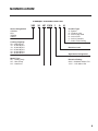
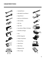
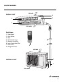
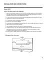
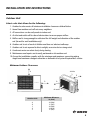
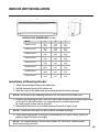
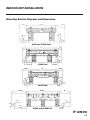
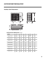
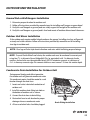
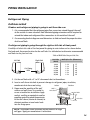
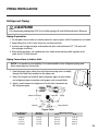
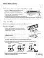
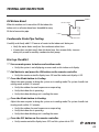
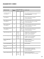
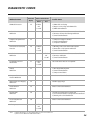
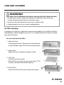
HIGH-WALL DUCTLESS
AIR CONDITIONING & HEATING SYSTEM
INSTALLATION MANUAL
Models:
VIR09HP115V1A
VIR12HP115V1A
VIR09HP230V1A
VIR12HP230V1A
VIR18HP230V1A
VIR24HP230V1A
VIR30HP230V1A
VIR36HP230V1A
Thank you for choosing a Vireo Heat Pump
for your customer.
Please read this installation manual carefully before installing and starting up the
Vireo System. Take a moment to fill out the product and installation form on the
back cover. Retain both the manual and installation record for future reference.
Table of Contents
Safety Precautions . . . . . . . . . . . . . . . . . . . . . . . . . . . . . . . . . . . . . . . . . . . 2-3
Nomenclature . . . . . . . . . . . . . . . . . . . . . . . . . . . . . . . . . . . . . . . . . . . . . . . . 4
System Requirements . . . . . . . . . . . . . . . . . . . . . . . . . . . . . . . . . . . . . . . . . . 5
Suggested Tools . . . . . . . . . . . . . . . . . . . . . . . . . . . . . . . . . . . . . . . . . . . . . . 6
Part Names . . . . . . . . . . . . . . . . . . . . . . . . . . . . . . . . . . . . . . . . . . . . . . . . . . 7
Installation Site Instructions . . . . . . . . . . . . . . . . . . . . . . . . . . . . . . . . . . . 8 - 9
Indoor Unit Installation . . . . . . . . . . . . . . . . . . . . . . . . . . . . . . . . . . . . . 10-11
Outdoor Unit Installation . . . . . . . . . . . . . . . . . . . . . . . . . . . . . . . . . . . 12-13
Piping Installation . . . . . . . . . . . . . . . . . . . . . . . . . . . . . . . . . . . . . . . . . 14 -17
Power and Wiring Installation . . . . . . . . . . . . . . . . . . . . . . . . . . . . . . . 18 -20
Testing and Inspection . . . . . . . . . . . . . . . . . . . . . . . . . . . . . . . . . . . . . 21-23
Troubleshooting . . . . . . . . . . . . . . . . . . . . . . . . . . . . . . . . . . . . . . . . . . . 24-25
Diagnostic Codes . . . . . . . . . . . . . . . . . . . . . . . . . . . . . . . . . . . . . . . . . . 26-28
Care and Cleaning . . . . . . . . . . . . . . . . . . . . . . . . . . . . . . . . . . . . . . . . . . . 29
SAFETY PRECAUTIONS
Please read the following before operation.
Recognize safety information.
This is the safety-alert symbol. When you see this
symbol on the unit and in instructions or manuals, be alert to the potential for personal
injury. Understand these signal words: DANGER, WARNING, and CAUTION. These
words are used with the safety-alert symbol.
DANGER identifies the most serious hazards which will result in severe personal injury
or death.
WARNING signifies hazards which could result in personal injury or death.
CAUTION is used to identify unsafe practices which may result in minor personal
injury or product and property damage.
NOTE is used to highlight suggestions which will result in enhanced installation,
reliability, or operation.
NOTE: Your actual air conditioning & heating system and related devices may differ
from the images shown in this manual.
WARNING
This appliance is not intended for use by children without responsible adult supervision.
Proper care should be taken to ensure safety.
WARNING
Heat pumps, air conditioners & heating equipment should be installed, started up, and
serviced only by qualified installers and service technicians. Air conditioning, heat pumps
and refrigeration systems are hazardous due to high voltage electrical components,
high refrigerant pressures, and moving parts.
2
SAFETY PRECAUTIONS
CAUTION
• The unit should be installed and serviced only by trained, qualified installers and service
technicians. Untrained personnel can perform basic maintenance functions such as
cleaning coils. All other operations should be performed by trained service personnel.
• Owner should be cautioned that children should not play with the appliance.
WARNING
ELECTRICAL SHOCK HAZARD
Failure to follow this warning could result in personal injury or death.
• Before installing, servicing or modifying the system, the main electrical disconnect
switch must be in the OFF position. There may be more than one disconnect switch.
Lock out and tag all switches with a warning label.
General Safety Precautions
• A dedicated power supply circuit should be used in accordance with local electrical
safety regulations and National Electrical Codes (NEC).
• Ensure that the entire system is properly grounded.
• Use a properly sized circuit breaker to protect equipment against short circuit and
overload conditions.
• The system must be positioned at least 5 feet from combustible surfaces.
• Observe all local codes and regulations.
Installation Site Instructions
A proper installation site is vital for correct and reliable operation of the system.
Avoid the following installation locations:
• High heat sources, vapors, flammable gas or volatile liquids.
• High-frequency electro-magnetic waves, generated by radio equipment, welders
or medical equipment.
3
NOMENCLATURE
Example: VIR24HP230V1AH
VIR
Series Designation
CROWN
RIO
TERRA
VIREO
Cooling Capacity
09 - 9,000 BTUH
12 - 12,000 BTUH
18 - 18,000 BTUH
24 - 24,000 BTUH
30 - 30,000 BTUH
36 - 36,000 BTUH
Model Type
AC - Cooling Only
HP - Heat Pump
HC - Heat/Cool
24
HP 230V 1
A
H
Product Type
S - System
O - Outdoor units
H - Indoor High Wall
D - Indoor Duct
C - Indoor Cassette
F - Indoor Floor/Ceiling
Revision Level
Style/Color Designation
Electrical Rating
230V - 208/230V 60Hz 1PH
115V - 115V 60Hz 1PH
4
SYSTEM REQUIREMENTS
PIPE SIZE in (mm)
Unit Size
(BtuH)
Voltage
115v - 1ph 60hz
115v - 1ph 60hz
208/230v - 1ph 60hz
208/230v - 1ph 60hz
208/230v - 1ph 60hz
208/230v - 1ph 60hz
208/230v - 1ph 60hz
208/230v - 1ph 60hz
9,000
12,000
9,000
12,000
18,000
24,000
30,000
36,000
Liquid Line
Suction/Gas Line
1/4 (6)
1/4 (6)
1/4 (6)
1/4 (6)
1/4 (6)
1/4 (6)
1/4 (6)
1/4 (6)
3/8 (9.5)
1/2 (12)
3/8 (9.5)
1/2 (12)
1/2 (12)
5/8 (16)
5/8 (16)
5/8 (16)
REFRIGERANT LINE LENGTHS ft (m)
Unit Size
(BtuH)
Voltage
Min Line
Length
Pre-Charge
Line Length
Max Line
Length
Max
Elevation
9,000
12,000
9,000
12,000
18,000
24,000
30,000
36,000
115v - 1ph 60hz
115v - 1ph 60hz
208/230v - 1ph 60hz
208/230v - 1ph 60hz
208/230v - 1ph 60hz
208/230v - 1ph 60hz
208/230v - 1ph 60hz
208/230v - 1ph 60hz
10 (3)
10 (3)
10 (3)
10 (3)
10 (3)
10 (3)
10 (3)
10 (3)
25 (7.5)
25 (7.5)
25 (7.5)
25 (7.5)
25 (7.5)
25 (7.5)
25 (7.5)
25 (7.5)
50 (15)
50 (15)
50 (15)
66 (20)
82 (25)
82 (25)
100 (30)
100 (30)
50 (15)
66 (20)
50 (15)
66 (20)
82 (25)
82 (25)
98 (30)
98 (30)
REFRIGERANT CHARGE
Unit Size
(BtuH)
Voltage
Refrigerant
Type
Factory System
Charge oz (kg)
Additional
Charge oz/ft (g/m)
9,000
12,000
9,000
12,000
18,000
24,000
30,000
36,000
115v - 1ph 60hz
115v - 1ph 60hz
208/230v - 1ph 60hz
208/230v - 1ph 60hz
208/230v - 1ph 60hz
208/230v - 1ph 60hz
208/230v - 1ph 60hz
208/230v - 1ph 60hz
R410A
R410A
R410A
R410A
R410A
R410A
R410A
R410A
42.3 (1.2)
47.6 (1.35)
45.9 (1.3)
47.6 (1.35)
56.4 (1.6)
77.6 (2.2)
84.7 (2.4)
91.7 (2.6)
0.21 (20)
0.21 (20)
0.21 (20)
0.21 (20)
0.21 (20)
0.54 (50)
0.54 (50)
0.54 (50)
Max Overcurrent
Protection (MOP)
Main Power
Wire Size (AWG)*
ELECTRICAL REQUIREMENTS
Unit Size
(BtuH)
Voltage
Min Circuit
Amps (MCA)
9,000
12,000
9,000
12,000
18,000
24,000
30,000
36,000
115v - 1ph 60hz
115v - 1ph 60hz
208/230v - 1ph 60hz
208/230v - 1ph 60hz
208/230v - 1ph 60hz
208/230v - 1ph 60hz
208/230v - 1ph 60hz
208/230v - 1ph 60hz
12
15
9
9
16
20
20
26
20
25
15
15
25
30
30
40
12
10
14
14
10
10
10
8
*Main power wire from electrical panel to outdoor unit.
Notes: 1) System must be on a single dedicated circuit.
2) Main power is supplied to the outdoor unit.
3) Use table above to size over current protection.
4) Follow all local building codes and NEC (National Electrical Code) regulations.
Interconnecting Cable: Recommended cable - 14/4 AWG stranded bare copper conductors THHN 600V unshielded wire
Note: Use shield cable if installation is in close proximity of RF and EMI transmitting devices.
Condensate Drain Size: 5/8-in OD 7/16-in ID
5
SUGGESTED TOOLS
• Standard Wrench
• Adjustable/Crescent Wrench
• Torque Wrench
• Hex Keys or Allen Wrenches
• Drill & Drill Bits
• Hole Saw
• Pipe Cutter
• Screw drivers (Phillips & Flat blade)
• Manifold and Gauges
• Level
• R410A Flaring Tool
• Clamp on Amp Meter
• Vacuum Pump
• Safety Glasses
• Work Gloves
• Refrigerant Scale
• Micron Gauge
6
PART NAMES
Indoor unit
Air inlet
1
2
3
4
Air outlet
Part Name
1.
2.
3.
4.
5.
6.
7.
8.
Front Panel
Aux. Button
Filter
Horizontal Louver
Remote Controller
Inter-Connection Wire
Drain Hose
Refrigerant Lines
5
Air inlet
6
Outdoor unit
7
Air outlet
8
7
INSTALLATION SITE INSTRUCTIONS
Indoor Unit
Select a site that allows for the following:
1. Ensure the installation complies with the installation minimum dimensions (defined below)
and meets the minimum and maximum connecting piping length and maximum change in
elevation as defined in the System Requirements section.
2. Air inlet and outlet will be clear of obstructions, ensuring proper airflow throughout the room.
3. Condensate can be easily and safely drained.
4. All connections can be easily made to outdoor unit.
5. Indoor unit is out of reach of children.
6. A mounting wall strong enough to withstand four times the full weight and vibration of the unit.
7. Filter can be easily accessed for cleaning.
8. Leave enough free space to allow access for routine maintenance.
9. Install at least 10 ft. (3 m) away from the antenna of TV set or radio. Operation of the air
conditioner may interfere with radio or TV reception in areas where reception is weak.
An amplifier may be required for the affected device.
10. Do not install in a laundry room or by a swimming pool due to the corrosive environment.
Minimum Indoor clearances
Ceiling
6 in (0.15m)
6 in
(0.15m)
6 in
(0.15m)
6 ft (1.8m)
Floor
8
INSTALLATION SITE INSTRUCTIONS
Outdoor Unit
Select a site that allows for the following:
1. Outdoor location meets all minimum installation clearances defined below.
2. Sound from outdoor unit will not annoy neighbors.
3. All connections can be easily made to indoor unit.
4. Air inlet and outlet will be clear of obstructions to ensure proper airflow.
5. Wall or roof is strong enough to withstand the full weight and vibration of the outdoor
unit (for wall or roof installation only).
6. Outdoor unit is out of reach of children and does not obstruct walkways.
7. Outdoor unit is not exposed to direct sunlight, excessive dust or strong wind.
8. Condensate water can drain freely during heating
9. Maintenance and repairs can be easily performed on the outdoor unit.
10. Ensure the installation complies with the minimum and maximum connecting piping
length and maximum change in elevation as defined in the System Requirements section.
Minimum Outdoor Clearances
A
Air inlet
E
B
C
D
Air outlet
Outdoor Unit
Minimum Distances
in (mm)
A
B
C
D
E
20 (500)
12 (305)
20 (500)
24 (610)
12 (305)
9
INDOOR UNIT INSTALLATION
A
C
B
INDOOR UNIT DIMENSIONS in (mm)
Model
A
B
C
VIR09HP115V1A
33.4
(848)
11.4
(290)
8.2
(208)
VIR12HP115V1A
33.4
(848)
11.4
(290)
8.2
(208)
VIR09HP230V1A
33.4
(848)
11.4
(290)
8.2
(208)
VIR12HP230V1A
33.4
(848)
11.4
(290)
8.2
(208)
VIR18HP230V1A
38.2
(970)
11.8
(300)
8.8
(224)
VIR24HP230V1A
42.4
(1077)
12.8
(325)
9.7
(246)
VIR30HP230V1A
53.1
(1349)
12.8
(325)
10
(254)
VIR36HP230V1A
53.1
(1349)
12.8
(325)
10
(254)
Installation of Mounting Bracket
1. Attach the mounting bracket to the indoor unit.
2. Find the horizontal center of the indoor unit.
3. Mark the center of the indoor unit on mounting bracket for future reference.
NOTE: The center of the mounting bracket is not the center of the indoor unit.
4. Remove the mounting brackets from the indoor unit and position the mounting bracket
on the wall in desired location. Use centering mark on mounting bracket
for centering the indoor unit on the wall.
5. Mounting bracket must be installed horizontally and level right to left.
NOTE: Condensate drain pan has built-in pitch for proper drainage.
6. Secure mounting bracket to wall with a minimum of five screws, evenly spaced to
properly support indoor unit weight.
NOTE: It is recommended to install screw anchors for sheet rock, concrete block,
brick and such type of walls.
10
INDOOR UNIT INSTALLATION
Mounting Bracket Diagrams and Dimensions
4 5/8
21 3/8
7 1/4
2 1/4
2 1/4
1 3/8
1 3/8
9,000 and 12,000 Units
4
27
7 1/4
2 1/4
2 1/4
1 1/2
7 1/2
8 1/9
1 1/2
18,000 Unit
27
5 1/2
7 3/8
2 3/4
2 3/4
1 5/8
6
13 3/4
1 5/8
24,000 Unit
3 1/8
29 3/8
10
2 3/4
2 3/4
1 1/2
11 5/8
3 1/2
30,000 and 36,000 Unit
11
OUTDOOR UNIT INSTALLATION
Outdoor Unit Dimensions
C
A
A
B
D
D
E
OUTDOOR UNIT DIMENSIONS in (mm)
Model
A
B
C
D
E
VIR09HP115V1A
21.3
(537)
11.3
(285)
21.3
(537)
33.4
(842)
12.6
(318)
VIR12HP115V1A
21.3
(537)
11.3
(285)
21.3
(537)
33.4
(842)
12.6
(318)
VIR09HP230V1A
21.3
(537)
11.3
(285)
21.3
(537)
33.4
(842)
12.6
(318)
VIR12HP230V1A
21.3
(537)
11.3
(285)
21.3
(537)
33.4
(842)
12.6
(318)
VIR18HP230V1A
22
(554)
14.3
(360)
27.6
(696)
37.6
(948)
15.6
(393)
VIR24HP230V1A
24
(605)
16.8
(423)
31.1
(784)
38.6
(973)
16.8
(423)
VIR30HP230V1A
24
(605)
16.8
(423)
31.1
(784)
38.6
(973)
16.8
(423)
VIR36HP230V1A
24
(605)
16.8
(423)
31.1
(784)
38.6
(973)
16.8
(423)
12
OUTDOOR UNIT INSTALLATION
Ground Pad or Wall Hangers Installation
1.
2.
3.
4.
Determine proper location for outdoor unit.
Follow all instructions provided by manufacturer for installing wall hangers or ground pad.
Verify the wall hangers or ground pad can safely support the weight of the outdoor unit.
Verify the wall hangers or ground pad is level and meets all outdoor dimensional clearances.
Outdoor Unit Risers Installation
If the outdoor unit requires added elevation above the ground, installing riser legs will provide
a sturdy and stable solution. Follow all instructions provided by manufacturer for installing
riser legs to outdoor unit.
NOTE: Riser legs will also help absorb vibrations and noise while facilitating proper drainage.
NOTE: To meet Florida Wind Load criteria, the outdoor unit must be anchored to concrete pad
using four 3/8 -in diameter Power Wedge Bolt Plus (or equivalent) with 1-in diameter fender
washers. Anchor bolts must be embedded into 3,000 PSI minimum concrete at a distance of
4 1/2 -in fromany concrete edge. The concrete thickness must exceed 1.5 times the anchor depth.
Condensate Drain Installation for Outdoor Unit
During normal heating and defrost operation,
the outdoor unit will generate condensate water.
The condensate water should be routed to a safe
location through the drain hose.
1. Locate and select a drain hole on bottom of
outdoor unit.
2. Install the outdoor drain fitting into hole on
the bottom of outdoor unit as shown.
3. Connect the drain hose to drain fitting.
4. Route drain hose to safe location for proper
drainage of excess condensate water.
Drain Fitting Installation
5. All non-used drain holes should be plugged.
13
PIPING INSTALLATION
Refrigerant Piping
Drill Hole in Wall
If indoor unit refrigerant piping is going to exit from the rear:
1. It is recommended that the refrigerant pipe flare connectors extend through the wall
to the outside. In some situations field-fabricated piping extensions will be required to
extend the indoor unit refrigerant flare connections to the outside of the wall.
2. Use mounting bracket diagrams and dimensions to find and mark the proper location
for the wall hole.
If refrigerant piping is going through the right or left side of front panel:
Carefully cut hole in the side of the front panel for piping to enter indoor unit as shown below.
Find and mark the proper location for the wall hole. Use table below to determine recommended
wall hole size for your unit size.
Table of Wall Hole Size per Unit Size
Left Side
Right Side
Cut Piping
Hole
Unit Size
(BtuH)
Wall Hole Size (Diameter)
9,000
12,000
18,000
24,000
30,000
36,000
in
2 1/4
2 1/4
2 3/4
2 3/4
2 3/4
2 3/4
mm
55
55
66
66
66
66
3. Cut the wall hole with a 5° to 10° downward slant to the outdoors.
4. Insert a wall sleeve into hole to prevent damage to refrigerant pipes, insulation,
condensate drain hose and wiring.
Indoor
Outdoor
5. Proper weather proofing of the wall
surface and wall sleeve is essential to
assure a trouble-free installation. Apply
sealant, caulking or equivalent weather
proofing material around the perimeter
of the wall sleeve (interior & exterior) to
eliminate outdoor air and water leaks
into the living space.
Wall
Hole Sleeve
Seal Hole
Hole Size
Wall Hole Diagram
NOTE: Expandable foam insulation may be added to fill large
wall gaps. Apply per manufacturer's instructions.
14
PIPING INSTALLATION
Refrigerant Piping
CAUTION
Use refrigeration grade piping ONLY. Uses of other piping will void the Manufacturer’s Warranty.
Piping Preparation:
1. Do not open service valves or remove protective caps on pipes until all connections are made.
2. Keep tubing free of dirt, sand, moisture and contaminants.
3. Insulate each refrigerant pipe and condensate hose with minimum 3/8” (10 mm) wall
thermal pipe insulation.
4. Bind refrigerant pipes, the condensate hose and interconnecting cable together with
cable ties at 12-inch intervals.
Piping Connections to Indoor Unit:
NOTE: For maximum serviceability, it is recommended to have refrigerant piping and
drain connections on the outside.
1. Feed refrigerant pipes, drain hose and interconnecting wires assembly
through wall hole from outdoor to the indoor unit.
2. Adjust the length and carefully bend refrigerant pipes to meet indoor
unit refrigerant pipe connections with proper tools to avoid kinks.
3. Apply a small amount of refrigerant oil to the flare connection on
the refrigerant pipes.
Indoor Unit Piping
Taper Nut
Wrench
Piping
Torque Wrench
Torque Table
Pipe Diameter
inch (mm)
Nut Size
inch (mm)
1/4 (6.35)
3/8 (9.5)
1/2 (12.7)
5/8 (15.9)
1/4 (17)
3/8 (22)
1/2 (25)
5/8 (29)
Tightening Torque
ft-lbs
N-m
10 to 13
25 to 30
36 to 45
50 to 60
14 to 18
34 to 42
49 to 61
68 to 82
15
PIPING INSTALLATION
Refrigerant Piping
Piping Connections to Indoor Unit (con’t):
4. Properly align piping and tighten flare nut using a standard wrench and a torque wrench
as shown in figure to the below. Carefully tighten flare nuts to correct torque level referring
to the Torque Table on page 15.
NOTE: Over tightening may damage flare connections and cause leaks.
5. Individually insulate each refrigerant line to
prevent sweating.
Insulate pipes
Piping Connections to Outdoor Unit:
1. Remove service valve cover (if provided) to
access the service valves and refrigerant ports.
2. Carefully bend and adjust length of refrigerant
pipes to meet outdoor unit service valves
connections with proper tools to avoid kinks.
Service
Valve Cover
NOTE: Use proper techniques to cut and re-flare
refrigerant pipes, if required. An R410A Flaring Tool
is required for re-flaring refrigerant pipes.
3. Apply a small amount of refrigerant oil to the flare connection on the refrigerant pipe.
4. Properly align piping and tighten flare nut using a standard wrench and a torque
wrench as shown in the indoor piping section.
5. Carefully tighten flare nuts to correct torque level referring to the Torque Table below.
Torque Table
Pipe Diameter
inch (mm)
Nut Size
inch (mm)
1/4 (6.35)
3/8 (9.5)
1/2 (12.7)
5/8 (15.9)
1/4 (17)
3/8 (22)
1/2 (25)
5/8 (29)
Tightening Torque
ft-lbs
N-m
10 to 13
25 to 30
36 to 45
50 to 60
14 to 18
34 to 42
49 to 61
68 to 82
16
PIPING INSTALLATION
How to Relocate Drain Hose from Left to Right Side (if required)
1. Locate drain plug on right side of the drain tray.
Firmly grab it and remove from drain tray.
Left
Right
2. Locate drain tube on the left side of drain tray.
Twist drain tube counter-clockwise and gently
pull to remove from the drain tray.
Rubber Plug
Drain
3. Position drain tube on the right side over the drain fitting.
Push drain tube onto fitting and rotate clockwise to lock. Verify drain tube is secure to prevent leaks.
4. Insert drain plug into left side of drain tray fitting. Verify plug is fully seated to prevent leaks.
Indoor Drain Piping
The Vireo indoor wall unit uses a gravity drain system. There is no internal
condensate pump. The drain hose must slope downward with no
kinks, raises or fluctuations.
1. Connect the field supplied drain hose to the outlet
pipe of indoor wall unit. A field supplied transition or
adapter may be required.
Outlet pipe
Drain hose
Drain hose
2. Apply pipe insulation to the entire drain line and joints
to prevent sweating.
3. The through-wall hole for the drain hose must be lower than
the indoor wall unit drain outlet for a functional gravity drain system.
Insulate
drain hose
4. Install field supplied drain hose with a downward slope from the Indoor wall unit
drain outlet to the drain hose outlet.
Correct
The drain hose
slopes downward.
Incorrect
The drain hose
cannot raise upward.
Incorrect
The drain hose
cannot raise upward.
5. Route the condensate drain hose in the safety location to
dispose of the condensate water.
17
POWER AND WIRING INSTALLATION
System Wiring Diagrams
Indoor Unit
Outdoor Unit
9,000 and 12,000 BtuH
(115V Models)
9,000 and 12,000 BtuH
(230V Models)
18,000 and 24,000 BtuH
(230V Models)
30,000 and 36,000 BtuH
(230V Models)
18
POWER AND WIRING INSTALLATION
Indoor Unit Wire Connections
WARNING
Disconnect all electrical power to indoor and outdoor units including disconnects,
fuses and circuit breakers. Lockout and tag all disconnect switches.
1. Open front cover of indoor unit and remove field wiring terminal block cover.
2. Pull interconnecting wires up from back of indoor unit and position in close to the
terminal block on indoor unit.
NOTE: Record wire colors and terminal references for uses with Outdoor Unit wire connections.
3. Connect wiring to indoor unit per system wiring diagram.
NOTE: The indoor unit is powered from the outdoor unit, depending on local code,
a disconnect switch may need to be installed to a power supply circuit.
4. Replace field wiring cover and close front cover of indoor unit.
Indoor Disconnect Switch ( If required)
Local codes may require a disconnect switch within sight of the indoor unit. Use a DFS
Disconnect Switch Accessory Kit (Part No: DFS-SWITCH-A) to break wires going to the
N(1), 2, 3, terminals on the indoor unit, as shown in the wiring diagram below:
Indoor Unit
Disconnect Switch
Indoor Unit
Outdoor Unit
Outdoor Unit
Wires
19
POWER AND WIRING INSTALLATION
Outdoor Unit Wire Connections
WARNING
Disconnect all electrical power to unit including disconnects, fuses and circuit breakers.
Lockout and tag all disconnect switches.
1. Remove the service panel on right side of the outdoor unit.
2. Insert interconnecting wires and main power wires through the wire holes on conduit
mounting bracket.
Cable Cross Board
3. Secure main power conduit (and interconnecting wire conduit, if required) with
locking nuts to conduit mounting bracket.
4. Open wire clamp/strain relief and adjust
wire lengths for proper connections to the
outdoor unit terminal block.
Wire Hole
5. Following the same wire colors and terminal references from the indoor unit, tightly
connect interconnecting wires to the outdoor unit terminal block per wiring diagram.
NOTE: Crossing interconnecting wires will cause system malfunction and possible damage.
6. Tightly connect main power wires to outdoor unit terminal block per system wiring diagram.
7. Secure all wires inside wire clamp/strain relief. Verify wires are secure, not loose and no
external force on wires affects the connections at the terminals.
8. Replace service panel on right side of the outdoor unit.
9. Connect main power wires and conduit to unit disconnect switch box (field supplied) per
manufacturer’s instructions, National Electrical Code (NEC) and local electrical codes.
CAUTION
• Electrical Disconnecting means must be provided and shall be located within sight and
readily accessible from the unit.
• Failure to follow this caution may result in equipment damage or improper operation.
• All wires running from the indoor to outdoor unit must comply with National Electrical
Code (NEC) and local codes.
• All wires must be connected firmly to terminal block to avoid unit malfunction,
overheating and possible fire hazard.
20
TESTING AND INSPECTION
Leaking Test
1. Connect the charging hose of the manifold valve to charge the end of the low-pressure valve.
2. Add dry nitrogen to a pressure of 200 lbs. Tightly close both high- and low-pressure valves.
3. Leak-test flare fittings with soap bubbles. If no leak is detected, release nitrogen.
CAUTION
Use vacuum pump, rather than refrigerant, to discharge air when installing the unit.
Vacuum Procedure
Important: Use a quality Micron Gauge to measure and validate the system vacuum achieved.
Do not rely on the scale of a“bourbon tube”type gauge set to validate the depth and quality
of the vacuum.
1. Remove the caps of the liquid valve, gas valve and service port.
2. Connect gauge manifold and micron gauge to the service ports provided at the liquid and
suction service valves.
3. Connect a vacuum pump to the manifold gauge.
4. Open the lower pressure side of the manifold valve assembly and start the vacuum pump.
The switch at the high pressure side of the manifold valve assembly should be kept closed,
or evacuation does not fail.
5. Operate vacuum pump until a vacuum of 500 microns or less is achieved. The evacuation
duration depends on the vacuum pump size and unit’s capacity, generally 20 minutes for
the 9,000 BtuH units, to 1 hour for a larger 36,000 BtuH unit.
6. Close the manifold valves and shut off the pump.
a. If vacuum holds below 700 microns for 15
minutes, the system can be considered dry
and leak free. Go to step 5.
b. If vacuum increases to 800 microns or greater,
this is an indication of moisture in system
or a leak exist. Identify leak and repair as
necessary, after which repeat steps 4 and 5.
If moisture is suspect, purge system use triple
evacuation method using dry nitrogen.
21
TESTING AND INSPECTION
Vacuum Procedure (con’t)
7. Confirm that manifold valves are closed and disconnect the vacuum pump.
8. Open the service valves to the fully ‘back-seat’ position to let the refrigerant flow to the
indoor unit and balance the pressure in system.
Important: Do not allow air to enter the connection pipe when removing the hose.
9. Replace service valve caps and tighten.
Pipe Testing
Gauge manifold
Pressure gauge (low-pressure)
Pressure gauge (hi-pressure)
Switch (low-pressure)
Switch (hi-pressure)
Connection pipe (to indoor unit)
Connection pipe
Cap
Low pressure gauge
High pressure gauge
Liquid valve
Gas valve
Gauge manifold kit
Service pipe
Hose
Service port
Hose
Cap
VAC valve
Cap
Hose with the valve pin
Service port
Vacuum pump
Vacuum pump
Additional Charge
The outdoor unit contains enough refrigerant charge for up to 25 feet from the factory. When the
piping is greater than 25 feet, additional charging is necessary. For the additional amount, see the
table below.
Model
Add’l Refrigerant Amount for Extra Pipe
9,000 -18,000
24,000 - 36,000
0.21 oz/ft
0.54 oz/ft
22
TESTING AND INSPECTION
Outdoor
Oil Return Bend
Oil return bend
20 ft.
When the outdoor unit is more than 30 feet above the
indoor unit, an oil return bend must be added for every
20 feet of connection pipe.
Indoor
Condensate Drain Pipe Testing
Oil return bend
Carefully and slowly add 8-10 ounces of water to the indoor unit drain pan.
• Verify the water drains easily out the condensate drain hose.
• If water does not drain easily from the drain hose, then remove kinks, increase
drain pitch, or add an auxiliary condensate drain pump.
Start-up Checklist
□ Turn on main power to indoor and outdoor units.
• Verify the system is not displaying an error code on the indoor unit display.
□ Add batteries and press the ON button on the remote controller.
• Verify the remote controller display turns ON and the indoor unit display is ON.
□ Press the Mode button to Cooling.
Adjust the room setpoint to bring the system on in cooling mode. The system should start
cooling mode within 3-5 minutes.
• Verify the outdoor fan and compressor are operating.
• Verify the indoor fan is operating.
• Verify the indoor discharge air is cooling the room.
□ Press the Mode button to Heating.
Adjust the room setpoint to bring the system on in cooling mode. The system should start
heating mode within 3-5 minutes.
• Verify the outdoor fan and compressor are operating.
• Verify the indoor fan is operating.
• Verify the indoor discharge air is cooling the room.
□ Press the OFF button on the remote controller.
• Verify remote controller display turns OFF and the system shuts OFF.
23
TROUBLESHOOTING
PROBLEM
CAUSE/SOLUTION
System does not restart.
Cause: The system has a built-in three-minute delay to prevent short and/or rapid
cycling of the compressor.
Solution: Wait three minutes for the protection delay to expire.
Indoor unit emits unpleasant odor
when started
Cause: Typically unpleasant odors are the result of mold or mildew forming on
the coil surfaces or the air filter.
Solution: Wash indoor air filter in warm water with mild cleaner. If odors persist,
contact a qualified service professional to clean the coil surfaces.
You hear a“water flowing”sound.
Cause: It is normal for the system to make“water flowing”or “gurgling”sounds
from refrigerant pressures equalizing when the compressor starts and stops
Solution: The noises should discontinue as the refrigerant system equalizes after
two or three minutes.
A thin fog or vapor coming out
of the indoor unit when system is
running.
You hear a slight cracking sound
when the system stops or starts.
Cause: It is normal for the system to emit a slight fog or water vapor when
cooling extremely humid warm air.
Solution: The fog or water vapor will disappear as the system cools and
dehumidifies the room space.
Cause: It is normal for the system to make “slight cracking” sounds from parts
expanding and contracting during system starts and stops.
Solution: The noises will discontinue as temperature equalizes after 2 or 3 minutes.
The system will not run.
Cause: There are a number of situations that will prevent the system from running.
Solution: Check for the following:
• Circuit breaker is “tripped” or “turned off.”
• Power button of remote is not turned on.
• Batteries in the remote controller are low.
• Remote controller is in sleep mode or timer mode.
• Otherwise, contact a qualified service professional for assistance.
The unit is not heating or cooling
adequately.
Water leakage from the
outdoor unit.
Cause: There are a number of reasons for inadequate cooling or heating.
Solution: Check the following:
• Remove obstructions blocking airflow into the room.
• Clean dirty or blocked air filter that is restricting airflow into the system.
• Seal around door or windows to prevent air infiltration into the room.
• Relocate or remove heat sources from the room.
Cause: It is normal for the outdoor unit to generate condensate water in the
reverse cycle heating and defrost mode.
Solution: This is normal. No action is required.
24
TROUBLESHOOTING
PROBLEM
CAUSE/SOLUTION
Water leaking from the indoor
unit into the room.
Cause: While it is normal for the system to generate condensate water in cooling
mode, it is designed to drain this water via a condensate drain system to a safe location.
Solution: If water is leaking into the room, it may indicate one of the following.
• The indoor unit is not level right to left. Level indoor unit.
• The condensate drain pipe is restricted or plugged. All restrictions must
be removed to allow continuous drainage by gravity.
• If problem persists, contact a qualified service professional for assistance.
Wireless remote controller
does not work.
Cause: There are a number of possible reasons
Solution: Check the following:
• The remote controller was not matched to the indoor unit.
See matching instructions.
• The batteries might be low. Change the batteries.
• The remote controller must be within 25 ft. (7.5 m) with no obstructions
of the indoor unit. If remote controller needs to be replaced, contact a
qualified service professional for assistance. In the meantime, use the
Aux button to operate the system.
The unit will not deliver air.
Cause: There are a number of system functions that will prevent air flow.
Solution: Check for the following:
• In heating mode, the indoor fan may not start for three minutes if the
room temperature is very low. This is to prevent blowing cold air.
• In heat mode, if the outdoor temperature is low and humidity is high,
the system may need to defrost for up to 10 minutes before beginning
a heating cycle.
• In dry mode, the indoor fan may stop for up to three minutes during the
compressor off delay.
• Otherwise, you should contact a qualified service professional for assistance.
Moisture or condensation
on the discharge air louvers
or outlet vents.
Cause: It is normal for the system to develop condensation or moisture on the
discharge air louvers when cooling warm humid air for a long period of time.
Solution: The condensation or moisture will disappear as the system cools and
dehumidifies the room space.
25
DIAGNOSTIC CODES
Troubleshooting
The Vireo System has onboard diagnostics. The outdoor unit will provide status indicators.
The indoor wall unit and remote controller will display error codes. The following is a summary
of the codes with explanation:
Malfunction Name
Indoor Unit
& Remote
Display
Outdoor Unit Indicators
Yellow
Possible Causes
Red
1) Over charged with refrigerant.
2) Blocked or dirty outdoor coil .
3) Extreme outdoor ambient conditions
System High Pressure
E1
Indoor Anti-Freeze Protection
E2
Refrigerant Leakage Protection
F0
Compressor High Discharge
Temperature Protection
E4
7 flashes
and
1 sec Off
Please refer to the malfunction analysis (discharge
temperature, overload) in service manual.
Overcurrent Protection
E5
5 flashes
and
1 sec Off
1) Supply voltage is unstable.
2) Supply voltage is too low and system load is too high.
3) Indoor coil is blocked or dirty.
Communication Malfunction
E6
Continuous
On
High Temperature
Resistant Protection
E8
6 flashes
and
1 sec Off
1) Incorrect refrigerant charge level.
2) Refrigerant metering device malfunction.
3) Compressor malfunction.
EEPROM Memory Malfunction
EE
11 flashes
and
1 sec Off
Control board malfunction.
System Configuration
Malfunction
C5
Pump Down or Gathering
Refrigerant Status
Fo
1) Low return airflow.
2) Indoor fan speed is too low.
3) Indoor coil is blocked or dirty.
3 flashes
and
1 sec Off
9 flashes
and
1 sec Off
1) refrigerant leak(s).
2) Indoor coil temperature sensor no calibrated.
3) Refrigerant flow is restricted ( ex. valve, exv, debris)
1) Communication cable is mis-wired between indoor
and outdoor units.
2) Indoor or Outdoor control board malfunction.
1) No jumper cap inserted on the control board.
2) Incorrect or damaged jumper cap on control board.
3) Indoor and outdoor units are not compatible.
17 flashes
and
1 sec Off
Optional Service Mode
26
DIAGNOSTIC CODES
Malfunction Name
Indoor Unit
Display
Outdoor Unit Indicators
Yellow
Possible Causes
Red
Indoor Ambient Temperature
Sensor Malfunction
F1
1) Loose or bad connection between sensor and control board.
2) Indoor ambient temperature sensor damaged.
3) Control board malfunction.
Indoor Coil Temperature
Sensor Malfunction
F2
1) Loose or bad connection between sensor and control board.
2) Indoor coil temperature sensor damaged.
3) Control board malfunction.
Outdoor Ambient Temperature
Sensor Malfunction
F3
6 flashes
and
1 sec Off
1) Loose or bad connection between sensor and control board.
2) Outdoor ambient temperature sensor damaged.
3) Control board malfunction.
Outdoor Coil Temperature
Sensor Malfunction
F4
5 flashes
and
1 sec Off
1) Loose or bad connection between sensor and control board.
2) Outdoor coil temperature sensor damaged.
3) Control board malfunction.
Outdoor Discharge Temperature
Sensor Malfunction
F5
7 flashes
and
1 sec Off
1) Loose or bad connection between sensor and control board.
2) Discharge temperature sensor damaged.
3) Control board malfunction.
High DC Bus Voltage Protection
PH
13 flashes
and
1 sec Off
1) Supply voltage on L1 and N is above 265Vac.
2) Capacitor on control board malfunction.
3) Outdoor control board malfunction.
Low DC Bus Voltage Protection
PL
12 flashes
and
1 sec Off
1) Supply voltage on L1 and N is below 150Vac.
2) Capacitor on control board malfunction.
3) Outdoor control board malfunction.
Compressor Phase Current
Protection
P5
1) IPM module malfunction.
2) Outdoor control board malfunction
3) Compressor malfunction.
Capacitor Charging Malfunction
PU
Capacitor malfunction
Module Temperature Sensor
Malfunction
P7
Outdoor control board malfunction
Module Temperature Protection
P8
1) Lack of thermal grease on IPM module.
2) Heat sink (radiator) not tightly mounted.
3) Control board malfunction.
Compressor Overload Protection
H3
8 flashes
and
1 sec Off
1) Wiring terminal OVC-COMP is loose.
2) Refer to the malfunction analysis in Service Manual.
27
DIAGNOSTIC CODES
Malfunction Name
Indoor Unit
Display
Outdoor Unit Indicators
Yellow
Possible Causes
Red
IPM Module Protection
H5
Indoor DC Fan Motor
Malfunction
H6
1) Loose connections between fan motor and control board
2) Fan motor or blower wheel bearings malfunction.
3) Control board malfunction.
Compressor De-Synchronized
Malfunction
H7
1) Compressor voltage is not balance.
2) Control board malfunction
3) Compressor malfunction
Power Factor Correction (PFC)
Protection
HC
Outdoor Fan Motor
Malfunction
L3
Incompatible Indoor and
Outdoor Units
LP
Start-Up
Malfunction
LC
1) Over charged with refrigerant.
2) Control board malfunction.
3) Compressor malefaction.
Compressor Phase-Current
Detection Malfunction
U1
Outdoor control board malfunction
DC Bus Voltage Level Dropping
Malfunction
U2
Unstable supply voltage
Current Detection
Malfunction
U3
Outdoor control board malfunction
Reversing Valve
Malfunction
U4
1) Voltage to reversing valve is less than 175V.
2) Loose connections between reversing valve and control board.
3) Reversing valve solenoid malfunction.
Zero Crossing Detection
Malfunction
U9
Outdoor control board malfunction
Defrosting Status
Notes:
note 1
1) IPM module over heating.
2) Improper or Low voltage at the IPM module.
3) IPM module malfunction.
4 flashes
and
1 sec Off
1) Mis-wiring of the reactor filter and PFC capacitor.
2) Reactor filter or PFC capacitor malfunction.
3) Control board malfunction.
14 flashes
and
1 sec Off
14 flashes
and
1 sec Off
16 flashes
and
1 sec Off
1) Loose connections between fan motor and control board
2) Fan motor malfunction.
3) Control board malfunction.
Indoor and outdoor units are not compatible.
16 flashes
and
1 sec Off
1) During defrosting process, the heating indicator is on for 10s and off for 0.5s.
2) Refer to Service Manual for additional information.
28
CARE AND CLEANING
WARNING
Take notice of the following items before cleaning the Vireo Indoor wall unit.
• To avoid electric shock or injury, do not attempt to clean the unit unless it has been
turned off and disconnected from the main power supply.
• Do not wash the unit with water; this may cause an electric shock.
• During cleaning, be sure to use a stable standing platform.
Air Filter Cleaning
Changing your air filter on a regular basis prevents many problems. Dirty air filters will affect
the performance and the longevity of your unit. It is recommended that air filters be cleaned
every three (3) months.
To access and clean the filter:
1. Open Front Panel
Firmly grasp both sides of the front panel and pull upward
to about 60 degree angle. (NOTE: do not force panel open).
2. Remove Filter
Remove the filter as indicated in the figure at right.
3. Clean Filter
Use vacuum to clean the filter.
When the filter is very dirty, use warm water (below 110°F)
to clean it, and then dry filter before replacing.
4. Reinstall Filter
Reinstall the filter and then close the panel cover tightly.
29
GREE ELECTRIC APPLIANCES, INC.
www.greecomfort.com
PRODUCT & INSTALLATION RECORD
For your convenience, please record the model and serial numbers of your new equipment in the
spaces provided. This information, along with the installation data and dealer contact information,
will be helpful should your system require maintenance or service.
UNIT INFORMATION
Outdoor Unit:
Model No.
Serial No.
Indoor Unit:
Model No.
Serial No.
INSTALLATION INFORMATION
Date Installed:
DEALERSHIP/INSTALLER INFORMATION
Company Name:
Address:
Phone Number:
Technician Name:
Gree Electric Appliances, Inc ©2015
Cat No: DFS-VIR-HP-1IN