1
SINUMERIK
SINUMERIK 808D ADVANCED
Commissioning Manual
Legal information
Warning notice system
This manual contains notices you have to observe in order to ensure your personal safety, as well as to prevent damage to property. The
notices referring to your personal safety are highlighted in the manual by a safety alert symbol, notices referring only to property damage
have no safety alert symbol. These notices shown below are graded according to the degree of danger.
DANGER
indicates that death or severe personal injury will result if proper precautions are not taken.
WARNING
indicates that death or severe personal injury may result if proper precautions are not taken.
CAUTION
indicates that minor personal injury can result if proper precautions are not taken.
NOTICE
indicates that property damage can result if proper precautions are not taken.
If more than one degree of danger is present, the warning notice representing the highest degree of danger will be used. A notice warning of
injury to persons with a safety alert symbol may also include a warning relating to property damage.
Qualified Personnel
The product/system described in this documentation may be operated only by personnel qualified for the specific task in accordance with
the relevant documentation, in particular its warning notices and safety instructions. Qualified personnel are those who, based on their
training and experience, are capable of identifying risks and avoiding potential hazards when working with these products/systems.
Proper use of Siemens products
Note the following:
WARNING
Siemens products may only be used for the applications described in the catalog and in the relevant technical documentation. If products
and components from other manufacturers are used, these must be recommended or approved by Siemens. Proper transport, storage,
installation, assembly, commissioning, operation and maintenance are required to ensure that the products operate safely and without any
problems. The permissible ambient conditions must be complied with. The information in the relevant documentation must be observed.
© Siemens AG 2015. All rights reserved
6FC5397-4EP10-0BA4, 08/2015
1
Preface
Applicable products
This manual is applicable to the following control systems:
Control system
Software version
SINUMERIK 808D ADVANCED T (Turning)
V4.6.2
SINUMERIK 808D ADVANCED M (Milling)
V4.6.2
Documentation components and target groups
Document
Recommended target group
Programming and Operating Manual (Turning)
Programmers and operators of turning machines
Programming and Operating Manual (Milling)
Programmers and operators of milling machines
Programming and Operating Manual (ISO Turning/Milling)
Programmers and operators of turning/milling machines
Programming and Operating Manual (Manual Machine Plus
(MM+), Turning)
Programmers and operators of turning machines
Diagnostics Manual
Mechanical and electrical designers, commissioning engineers, machine operators, and service and maintenance
personnel
Manufacturer/service documentation
Commissioning Manual
Installation personnel, commissioning engineers, and service and maintenance personnel
Function Manual
Mechanical and electrical designers, technical professionals
Parameter Manual
Mechanical and electrical designers, technical professionals
Service Manual
Mechanical and electrical designers, technical professionals, commissioning engineers, and service and maintenance
personnel
My Documentation Manager (MDM)
Under the following link you will find information to individually compile your documentation based on the Siemens content:
www.siemens.com/mdm
Standard scope
This manual only describes the functionality of the standard version. Extensions or changes made by the machine tool
manufacturer are documented by the machine tool manufacturer.
Technical support
Country
Hotline 1)
Germany
+49 911 895 7222
China
+86 400 810 4288
Further service contact information:
• Global Web site:
•
https://support.industry.siemens.com/sc/us/en/sc/list-of-countries/oid2044
Chinese Web site:
http://www.siemens.com.cn/808D
1)
You can find more hotline information at the global Web site given above.
EC Declaration of Conformity
The EC Declaration of Conformity for the EMC Directive can be found on the Internet at
http://www.siemens.com/automation/service&support.
Here, enter the number 67385845 as the search term or contact your local Siemens office.
2
Commissioning Manual
6FC5397-4EP10-0BA4, 08/2015
Table of contents
Preface................................................................................................................................................................... 2
1
2
3
4
Safety instructions .................................................................................................................................................. 7
1.1
1.1.1
1.1.2
1.1.3
1.1.4
1.1.5
Fundamental safety instructions .............................................................................................................. 7
General safety instructions ...................................................................................................................... 7
Handling electrostatic sensitive devices (ESD) ..................................................................................... 10
Industrial security .................................................................................................................................. 11
Residual risks of power drive systems................................................................................................... 11
Residual risks during the operation of electric motors ........................................................................... 12
1.2
Carrying out of repairs ........................................................................................................................... 13
Scope of delivery .................................................................................................................................................. 13
2.1
System overview ................................................................................................................................... 13
2.2
PPU and MCP ....................................................................................................................................... 16
2.3
Drives and motors ................................................................................................................................. 17
2.4
Cables ................................................................................................................................................... 21
2.5
Options .................................................................................................................................................. 22
Mounting .............................................................................................................................................................. 25
3.1
Mounting the PPU and MCP ................................................................................................................. 26
3.2
3.2.1
3.2.2
3.2.3
3.2.4
3.2.4.1
3.2.4.2
Mounting the drive ................................................................................................................................. 31
Mounting orientation and clearance ...................................................................................................... 31
Drill patterns and outline dimensions ..................................................................................................... 32
Mounting the drive ................................................................................................................................. 33
Electrical cabinet design ........................................................................................................................ 34
Correct installation of fans ..................................................................................................................... 34
Correct installation of cooling units ........................................................................................................ 35
3.3
3.3.1
3.3.2
Mounting the motor................................................................................................................................ 35
Mounting orientation and outline dimensions ........................................................................................ 35
Mounting the motor................................................................................................................................ 39
3.4
Notes on the laying of cables in drag chains ......................................................................................... 40
Connecting ........................................................................................................................................................... 41
4.1
4.1.1
4.1.2
4.1.3
4.1.4
4.1.5
4.1.6
4.1.7
4.1.8
4.1.9
4.1.10
4.1.11
4.1.12
4.1.13
Interfaces on the PPU and MCP ........................................................................................................... 41
Digital input interfaces - X100, X101, X102 ........................................................................................... 43
Digital output interfaces - X200, X201 ................................................................................................... 44
Fast input/output - X21 .......................................................................................................................... 45
Distributed I/O - X301, X302.................................................................................................................. 46
Handwheel inputs - X10 ........................................................................................................................ 49
Drive Bus interface - X126..................................................................................................................... 50
Analog spindle interface - X54, spindle encoder interface - X60 ........................................................... 51
Ethernet interface - X130....................................................................................................................... 53
RS232 interface - X2 ............................................................................................................................. 54
Power supply interface - X1................................................................................................................... 55
USB interface on the front cover of the PPU ......................................................................................... 55
USB interface - X30 ............................................................................................................................... 55
Slot for the system CF card ................................................................................................................... 56
4.2
4.2.1
4.2.1.1
4.2.1.2
4.2.2
4.2.3
4.2.4
4.2.5
Interfaces on the SINAMICS V70 servo system .................................................................................... 57
Main circuit wiring .................................................................................................................................. 59
Main circuit interfaces ............................................................................................................................ 59
Main circuit wiring .................................................................................................................................. 60
Connecting the 24 V power supply/STO - X6 ........................................................................................ 60
Connecting the holding brake - X7 ........................................................................................................ 63
Connecting the encoder - X9 ................................................................................................................. 63
Connecting an external braking resistor - DCP, R1 ............................................................................... 65
Commissioning Manual
6FC5397-4EP10-0BA4, 08/2015
3
4.3
4.3.1
4.3.2
5
6
7
8
9
4
System connection overview................................................................................................................. 66
Connecting the CNC controller ............................................................................................................. 66
Connecting the drive and motor ............................................................................................................ 67
Toolbox software ...................................................................................................................................................70
5.1
Installing the software tools ................................................................................................................... 70
5.2
Overview of PLC Programming Tool ..................................................................................................... 73
Initial commissioning .............................................................................................................................................75
6.1
6.1.1
6.1.2
Switching on the SINAMICS V70 drive ................................................................................................. 75
Jog test ................................................................................................................................................. 75
Configuring Drive Bus addresses .......................................................................................................... 78
6.2
Switching on the control system ............................................................................................................ 79
6.3
Synchronizing drive data files between NC and drive ........................................................................... 79
6.4
Setting the password............................................................................................................................. 81
6.5
Setting the date and time ...................................................................................................................... 82
6.6
Activating the optional functions ............................................................................................................ 83
6.7
Loading system languages ................................................................................................................... 85
6.8
Overview on commissioning and operation wizards.............................................................................. 86
Commissioning the prototype machine...................................................................................................................88
7.1
7.1.1
7.1.2
7.1.3
7.1.4
Commissioning the PLC........................................................................................................................ 88
Setting PLC related parameters ............................................................................................................ 88
Downloading and commissioning PLC programs .................................................................................. 90
Checking I/O address assignment ........................................................................................................ 91
Editing PLC alarm texts......................................................................................................................... 91
7.2
Configuring the drives ........................................................................................................................... 92
7.3
7.3.1
7.3.2
7.3.3
Setting basic parameters ...................................................................................................................... 94
Setting feed axis parameters ................................................................................................................ 94
Commissioning the referencing function ............................................................................................... 95
Setting spindle parameters ................................................................................................................... 97
7.4
Creating series archives........................................................................................................................ 99
7.5
7.5.1
7.5.2
7.5.3
Setting compensation data.................................................................................................................. 100
Setting software limit switch data ........................................................................................................ 100
Setting backlash compensation data .................................................................................................. 101
Setting leadscrew error compensation data ........................................................................................ 102
7.6
Tuning drive performance ................................................................................................................... 103
7.7
Creating prototype machine commissioning archives ......................................................................... 105
Series machine commissioning ............................................................................................................................ 106
8.1
Loading series commissioning archives .............................................................................................. 106
8.2
Setting software limit switch data ........................................................................................................ 107
8.3
Setting backlash compensation data .................................................................................................. 107
8.4
Setting leadscrew error compensation data ........................................................................................ 107
8.5
Tuning drive performance ................................................................................................................... 107
8.6
Backing up series machine archives ................................................................................................... 107
Other frequently used functions ........................................................................................................................... 108
9.1
Playing a slide show............................................................................................................................ 108
9.2
Defining the service planner................................................................................................................ 110
9.3
Using the machine manufacturer startup screen and machine logo ................................................... 112
9.4
9.4.1
Creating user cycles............................................................................................................................ 116
Creating the extended user text file..................................................................................................... 116
Commissioning Manual
6FC5397-4EP10-0BA4, 08/2015
10
A
9.4.2
9.4.3
9.4.4
9.4.5
9.4.6
9.4.7
9.4.8
9.4.9
Creating the user cycle softkey index file ............................................................................................ 116
Creating the user cycle parameter file ................................................................................................. 117
Creating the user cycle file .................................................................................................................. 118
Creating the user cycle alarm file ........................................................................................................ 119
Creating the user cycle bitmap file ...................................................................................................... 120
Transferring the desired files to the control system ............................................................................. 120
Call the created user cycle .................................................................................................................. 123
Editing the user cycle screens ............................................................................................................. 124
9.5
Loading machine manufacturer's MD description files ........................................................................ 124
9.6
Loading machine manufacturer's R variable name files ...................................................................... 126
Technical data .................................................................................................................................................... 127
10.1
SINUMERIK 808D ADVANCED .......................................................................................................... 127
10.2
SINAMICS V70 servo drives ............................................................................................................... 128
10.3
SIMOTICS S-1FL6 servo motors ......................................................................................................... 130
10.4
10.4.1
10.4.2
Cables ................................................................................................................................................. 134
Drive Bus cable/Drive Bus trailing cable for the SINUMERIK 808D ADVANCED ............................... 134
Technical data - cables for the SINAMICS V70 servo system ............................................................. 134
Appendix ............................................................................................................................................................ 135
A.1
A.1.1
A.1.2
A.1.3
A.1.3.1
A.1.3.2
A.1.3.3
A.1.3.4
A.1.3.5
A.1.4
Operation and display.......................................................................................................................... 135
Elements on the PPU .......................................................................................................................... 135
Elements on the MCP.......................................................................................................................... 136
Operating the SINAMICS V70 Basic Operator Panel (BOP) ............................................................... 138
BOP overview...................................................................................................................................... 138
Parameter structure ............................................................................................................................. 141
Actual status display ............................................................................................................................ 142
Basic operations .................................................................................................................................. 142
Auxiliary functions................................................................................................................................ 144
Status indicators .................................................................................................................................. 148
A.2
A.2.1
A.2.2
A.2.3
A.2.4
Configuring the additional axis ............................................................................................................ 150
Setting parameters for the additional axis (turning) ............................................................................. 150
Setting parameters for the additional axis (milling) .............................................................................. 151
Configuring the drive and motor .......................................................................................................... 152
Tuning drive performance.................................................................................................................... 153
A.3
Cutting reserved holes in the MCP ...................................................................................................... 154
A.4
MCP strips ........................................................................................................................................... 155
A.5
A.5.1
A.5.2
Parameter list ...................................................................................................................................... 157
Recommended machine data.............................................................................................................. 157
SINAMICS V70 parameters................................................................................................................. 161
A.6
A.6.1
A.6.2
A.6.2.1
A.6.2.2
Diagnostics .......................................................................................................................................... 169
SINUMERIK 808D ADVANCED alarms .............................................................................................. 169
SINAMICS V70 faults and alarms ....................................................................................................... 169
General information about faults and alarms ....................................................................................... 169
List of faults and alarms....................................................................................................................... 170
A.7
A.7.1
A.7.1.1
A.7.1.2
A.7.1.3
A.7.1.4
A.7.1.5
A.7.1.6
A.7.2
A.7.2.1
A.7.2.2
A.7.2.3
A.7.2.4
A.7.2.5
A.7.2.6
PLC program design and adjustment .................................................................................................. 181
PLC Programming Tool ....................................................................................................................... 181
Renaming the default program ............................................................................................................ 181
Changing the display language ........................................................................................................... 182
Selecting a target system .................................................................................................................... 183
Establishing a connection between the control system and the PC .................................................... 184
Downloading/uploading/comparing PLC applications .......................................................................... 191
Compiling and monitoring programs .................................................................................................... 200
PLC user interface ............................................................................................................................... 203
Signals from/to the MCP...................................................................................................................... 205
Reading/Writing NC data ..................................................................................................................... 206
PI Service ............................................................................................................................................ 207
Retentive data area ............................................................................................................................. 207
User Alarms......................................................................................................................................... 208
Signals from/to HMI ............................................................................................................................. 209
Commissioning Manual
6FC5397-4EP10-0BA4, 08/2015
5
6
A.7.2.7
A.7.2.8
A.7.2.9
A.7.2.10
A.7.2.11
A.7.2.12
A.7.2.13
A.7.2.14
A.7.2.15
A.7.3
A.7.4
A.7.4.1
A.7.4.2
A.7.4.3
A.7.4.4
A.7.4.5
A.7.4.6
A.7.4.7
A.7.4.8
A.7.4.9
A.7.4.10
A.7.4.11
A.7.4.12
A.7.4.13
A.7.4.14
A.7.4.15
A.7.4.16
A.7.4.17
A.7.4.18
A.7.4.19
A.7.4.20
A.7.4.21
A.7.4.22
A.7.4.23
A.7.4.24
A.7.4.25
A.7.4.26
A.7.4.27
A.7.4.28
A.7.4.29
A.7.4.30
A.7.4.31
A.7.4.32
A.7.4.33
A.7.4.34
A.7.4.35
A.7.5
A.7.5.1
A.7.5.2
A.7.6
A.7.6.1
A.7.6.2
Auxiliary functions transfer from NC channel ...................................................................................... 213
NCK signals ........................................................................................................................................ 215
Channel signals .................................................................................................................................. 218
Axis/spindle signals ............................................................................................................................. 223
PLC machine data............................................................................................................................... 228
Signals, synchronized actions ............................................................................................................. 229
Axis actual values and distance-to-go ................................................................................................. 230
Maintenance scheduler: User interface ............................................................................................... 230
User interface for ctrl energy ............................................................................................................... 231
Operation symbols of PLC programming languages ........................................................................... 233
PLC subroutine library......................................................................................................................... 237
PLC machine data............................................................................................................................... 240
Conventions for the symbols used in the subroutines ......................................................................... 241
Subroutine 20 - AUX_MCP (machine auxiliary functions) ................................................................... 242
Subroutine 21 - AUX_LAMP (working lamp) ....................................................................................... 242
Subroutine 22 - AUX_SAFE_DOOR (safety door) .............................................................................. 243
Subroutine 23 - AUX_CHIP (chip conveyor) ....................................................................................... 243
Subroutine 31 - PLC_ini_USR_ini (user initialization) .......................................................................... 244
Subroutine 32 - PLC_INI (PLC initialization) ....................................................................................... 244
Subroutine 33 - EMG_STOP ............................................................................................................... 245
Subroutine 37 - MCP_NCK (MCP and HMI signal processing) ........................................................... 246
Subroutine 38 - MCP_Tool_Nr (display tool number on the MCP) ...................................................... 248
Subroutine 39 - HANDWHL (selecting a handwheel according to HMI interface signals) ................... 248
Subroutine 40 - AXIS_CTL (controlling the spindle and axes) ............................................................ 249
Subroutine 41 - MINI_HHU (handwheel on hand-held unit) ................................................................ 251
Subroutine 42 - SPINDLE (spindle control) ......................................................................................... 253
Subroutine 43 - MEAS_JOG (measurement in the JOG mode) .......................................................... 254
Subroutine 44 - COOLING (cooling control)........................................................................................ 255
Subroutine 45 - LUBRICAT (control of lubricate) ................................................................................ 256
Subroutine 46 - PI_SERVICE.............................................................................................................. 257
Subroutine 47 - PLC_Select_PP (PLC selects a subroutine) .............................................................. 258
Subroutine 48 - ServPlan (service planner) ........................................................................................ 259
Subroutine 49 - GearChg1_Auto (automatic spindle gear change) ..................................................... 260
Subroutine 50 - GearChg2_Virtual (virtual spindle gear change) ........................................................ 261
Subroutine 51 - Turret1_HED_T (turret with Hall effect device position sensor) ................................. 262
Subroutine 52 - TURRET2_BIN_T (turret with binary coding function)................................................ 264
Subroutine 53 - Turret3_CODE_T (tool change control for turret with coding function) ...................... 266
Subroutine 54 - Turret2_3_ToolDir (tool change direction).................................................................. 267
Subroutine 55 - Tail_stock_T (Tailstock control program for turning machines) .................................. 268
Subroutine 56 - Lock_unlock_T (clamping control for turning machine) .............................................. 269
Subroutine 58 (MM_MAIN).................................................................................................................. 270
Subroutine 59 (MM_MCP_808D) ........................................................................................................ 273
Subroutine 60 - Disk_MGZ_M (disk-style tool magazine used for milling)........................................... 273
Subroutines 34 to 36, 57, and 61 ........................................................................................................ 275
Subroutine 62 - Trg_key_OR............................................................................................................... 275
Subroutine 63 - TOGGLES ................................................................................................................. 277
PLC alarms ......................................................................................................................................... 278
Alarm cancel/reset and reaction .......................................................................................................... 280
Alarm texts .......................................................................................................................................... 280
PLC sample applications..................................................................................................................... 282
PLC sample application (turning) ........................................................................................................ 282
PLC sample application (milling) ......................................................................................................... 284
A.8
A.8.1
A.8.2
A.8.3
A.8.3.1
A.8.3.2
AMM communication tool .................................................................................................................... 287
Establishing an Ethernet connection ................................................................................................... 287
File management and transfer ............................................................................................................ 290
Remote control .................................................................................................................................... 291
Operating the HMI via remote control ................................................................................................. 293
Saving the remote control screen as a picture .................................................................................... 293
Commissioning Manual
6FC5397-4EP10-0BA4, 08/2015
1
Safety instructions
1.1
Fundamental safety instructions
1.1.1
General safety instructions
DANGER
Danger to life due to live parts and other energy sources
Death or serious injury can result when live parts are touched.
• Only work on electrical devices when you are qualified for this job.
• Always observe the country-specific safety rules.
Generally, six steps apply when establishing safety:
1. Prepare for shutdown and notify all those who will be affected by the procedure.
2. Disconnect the machine from the supply.
– Switch off the machine.
– Wait until the discharge time specified on the warning labels has elapsed.
– Check that it really is in a no-voltage condition, from phase conductor to phase conductor and phase
conductor to protective conductor.
– Check whether the existing auxiliary supply circuits are de-energized.
– Ensure that the motors cannot move.
3. Identify all other dangerous energy sources, e.g. compressed air, hydraulic systems, or water.
4. Isolate or neutralize all hazardous energy sources by closing switches, grounding or short-circuiting or
closing valves, for example.
5. Secure the energy sources against switching on again.
6. Ensure that the correct machine is completely interlocked.
After you have completed the work, restore the operational readiness in the inverse sequence.
WARNING
Danger to life through a hazardous voltage when connecting an unsuitable power supply
Touching live components can result in death or severe injury.
• Only use power supplies that provide SELV (Safety Extra Low Voltage) or PELV- (Protective Extra Low
Voltage) output voltages for all connections and terminals of the electronics modules.
WARNING
Danger to life when live parts are touched on damaged motors/devices
Improper handling of motors/devices can damage them.
For damaged motors/devices, hazardous voltages can be present at the enclosure or at exposed components.
• Ensure compliance with the limit values specified in the technical data during transport, storage and operation.
• Do not use any damaged motors/devices.
WARNING
Danger to life through electric shock due to unconnected cable shields
Hazardous touch voltages can occur through capacitive cross-coupling due to unconnected cable shields.
• As a minimum, connect cable shields and the cores of cables that are not used at one end at the grounded
housing potential.
Commissioning Manual
6FC5397-4EP10-0BA4, 08/2015
7
WARNING
Danger to life due to electric shock when not grounded
For missing or incorrectly implemented protective conductor connection for devices with protection class I, high
voltages can be present at open, exposed parts, which when touched, can result in death or severe injury.
• Ground the device in compliance with the applicable regulations.
WARNING
Danger to life due to electric shock when opening plug connections in operation
When opening plug connections in operation, arcs can result in severe injury or death.
• Only open plug connections when the equipment is in a no-voltage state, unless it has been explicitly stated
that they can be opened in operation.
WARNING
Danger to life due to fire spreading if housing is inadequate
Fire and smoke development can cause severe personal injury or material damage.
• Install devices without a protective housing in a metal control cabinet (or protect the device by another equivalent
measure) in such a way that contact with fire is prevented.
• Ensure that smoke can only escape via controlled and monitored paths.
WARNING
Danger to life through unexpected movement of machines when using mobile wireless devices or mobile phones
Using mobile wireless devices or mobile phones with a transmit power > 1 W closer than approx. 2 m to the components
may cause the devices to malfunction, influence the functional safety of machines therefore putting people at risk or
causing material damage.
• Switch the wireless devices or mobile phones off in the immediate vicinity of the components.
WARNING
Danger to life due to the motor catching fire in the event of insulation overload
There is higher stress on the motor insulation through a ground fault in an IT system. If the insulation fails, it is possible that
death or severe injury can occur as a result of smoke and fire.
• Use a monitoring device that signals an insulation fault.
• Correct the fault as quickly as possible so the motor insulation is not overloaded.
WARNING
Danger to life due to fire if overheating occurs because of insufficient ventilation clearances
Inadequate ventilation clearances can cause overheating of components with subsequent fire and smoke. This can cause
severe injury or even death. This can also result in increased downtime and reduced service lives for devices/systems.
• Ensure compliance with the specified minimum clearance as ventilation clearance for the respective component.
WARNING
Danger of an accident occurring due to missing or illegible warning labels
Missing or illegible warning labels can result in accidents involving death or serious injury.
• Check that the warning labels are complete based on the documentation.
• Attach any missing warning labels to the components, in the national language if necessary.
• Replace illegible warning labels.
8
Commissioning Manual
6FC5397-4EP10-0BA4, 08/2015
NOTICE
Device damage caused by incorrect voltage/insulation tests
Incorrect voltage/insulation tests can damage the device.
• Before carrying out a voltage/insulation check of the system/machine, disconnect the devices as all converters and
motors have been subject to a high voltage test by the manufacturer, and therefore it is not necessary to perform an
additional test within the system/machine.
WARNING
Danger to life when safety functions are inactive
Safety functions that are inactive or that have not been adjusted accordingly can cause operational faults on machines that
could lead to serious injury or death.
• Observe the information in the appropriate product documentation before commissioning.
• Carry out a safety inspection for functions relevant to safety on the entire system, including all safety-related
components.
• Ensure that the safety functions used in your drives and automation tasks are adjusted and activated through
appropriate parameterizing.
• Perform a function test.
• Only put your plant into live operation once you have guaranteed that the functions relevant to safety are running
correctly.
Note
Important safety notices for Safety Integrated functions
If you want to use Safety Integrated functions, you must observe the safety notices in the Safety Integrated manuals.
WARNING
Danger to life or malfunctions of the machine as a result of incorrect or changed parameterization
As a result of incorrect or changed parameterization, machines can malfunction, which in turn can lead to injuries or death.
• Protect the parameterization (parameter assignments) against unauthorized access.
• Respond to possible malfunctions by applying suitable measures (e.g. EMERGENCY STOP or EMERGENCY OFF).
WARNING
Danger to life from permanent magnet fields
Even when switched off, electric motors with permanent magnets represent a potential risk for persons with heart
pacemakers or implants if they are close to converters/motors.
• If you are such a person (with heart pacemaker or implant) then keep a minimum distance of 2 m.
• When transporting or storing permanent magnet motors always use the original packing materials with the warning
labels attached.
• Clearly mark the storage locations with the appropriate warning labels.
• IATA regulations must be observed when transported by air.
WARNING
Injury caused by moving parts or those that are flung out
Touching moving motor parts or drive output elements and loose motor parts that are flung out (e.g. feather keys) in
operation can result in severe injury or death.
• Remove any loose parts or secure them so that they cannot be flung out.
• Do not touch any moving parts.
• Safeguard all moving parts using the appropriate safety guards.
Commissioning Manual
6FC5397-4EP10-0BA4, 08/2015
9
WARNING
Danger to life due to fire if overheating occurs because of insufficient cooling
Inadequate cooling can cause overheating resulting in death or severe injury as a result of smoke and fire. This can also
result in increased failures and reduced service lives of motors.
• Comply with the specified coolant requirements for the motor.
WARNING
Danger to life due to fire as a result of overheating caused by incorrect operation
When incorrectly operated and in the case of a fault, the motor can overheat resulting in fire and smoke. This can result in
severe injury or death. Further, excessively high temperatures destroy motor components and result in increased failures
as well as shorter service lives of motors.
• Operate the motor according to the relevant specifications.
• Only operate the motors in conjunction with effective temperature monitoring.
• Immediately switch off the motor if excessively high temperatures occur.
CAUTION
Risk of injury due to touching hot surfaces
In operation, the motor can reach high temperatures, which can cause burns if touched.
• Mount the motor so that it is not accessible in operation.
• When maintenance is required, allow the motor to cool down before starting any work.
• Use the appropriate personnel protection equipment, e.g. gloves.
WARNING
Danger to life from electromagnetic fields
Electromagnetic fields (EMF) are generated by the operation of electrical power equipment such as
transformers, converters or motors.
People with pacemakers or implants are at a special risk in the immediate vicinity of these devices/systems.
• Ensure that the persons involved are the necessary distance away (minimum 2 m).
1.1.2
Handling electrostatic sensitive devices (ESD)
Electrostatic sensitive devices (ESD) are individual components, integrated circuits, modules or devices that may be
damaged by either electric fields or electrostatic discharge.
NOTICE
Damage through electric fields or electrostatic discharge
Electric fields or electrostatic discharge can cause malfunctions through damaged individual components,
integrated circuits, modules or devices.
• Only pack, store, transport and send electronic components, modules or devices in their original packaging
or in other suitable materials, e.g conductive foam rubber of aluminum foil.
• Only touch components, modules and devices when you are grounded by one of the following methods:
– Wearing an ESD wrist strap
– Wearing ESD shoes or ESD grounding straps in ESD areas with conductive flooring
• Only place electronic components, modules or devices on conductive surfaces (table with ESD surface,
conductive ESD foam, ESD packaging, ESD transport container).
10
Commissioning Manual
6FC5397-4EP10-0BA4, 08/2015
1.1.3
Industrial security
Note
Industrial security
Siemens provides products and solutions with industrial security functions that support the secure operation of plants,
solutions, machines, equipment and/or networks. They are important components in a holistic industrial security concept.
With this in mind, Siemens’ products and solutions undergo continuous development. Siemens recommends strongly that
you regularly check for product updates.
For the secure operation of Siemens products and solutions, it is necessary to take suitable preventive action (e.g. cell
protection concept) and integrate each component into a holistic, state-of-the-art industrial security concept. Third-party
products that may be in use should also be considered. For more information about industrial security, visit this address
(http://www.siemens.com/industrialsecurity).
To stay informed about product updates as they occur, sign up for a product-specific newsletter. For more information, visit
this address (http://support.automation.siemens.com).
WARNING
Danger as a result of unsafe operating states resulting from software manipulation
Software manipulation (e.g. by viruses, Trojan horses, malware, worms) can cause unsafe operating states to develop in
your installation which can result in death, severe injuries and/or material damage.
• Keep the software up to date.
You will find relevant information and newsletters at this address (http://support.automation.siemens.com).
• Incorporate the automation and drive components into a holistic, state-of-the-art industrial security concept for the
installation or machine.
You will find further information at this address (http://www.siemens.com/industrialsecurity).
• Make sure that you include all installed products into the holistic industrial security concept.
1.1.4
Residual risks of power drive systems
The control and drive components of a drive system are approved for industrial and commercial use in industrial line
supplies. Their use in public line supplies requires a different configuration and/or additional measures.
These components may only be operated in closed housings or in higher-level control cabinets with protective covers that
are closed, and when all of the protective devices are used.
These components may only be handled by qualified and trained technical personnel who are knowledgeable and observe
all of the safety instructions on the components and in the associated technical user documentation.
When assessing the machine's risk in accordance with the respective local regulations (e.g., EC Machinery Directive), the
machine manufacturer must take into account the following residual risks emanating from the control and drive components
of a drive system:
1. Unintentional movements of driven machine components during commissioning, operation, maintenance, and repairs
caused by, for example,
– Hardware and/or software errors in the sensors, control system, actuators, and cables and connections
– Response times of the control system and of the drive
– Operation and/or environmental conditions outside the specification
– Condensation/conductive contamination
– Parameterization, programming, cabling, and installation errors
– Use of wireless devices/mobile phones in the immediate vicinity of the control system
– External influences/damage
2. In the event of a fault, exceptionally high temperatures, including an open fire, as well as emissions of light, noise,
particles, gases, etc. can occur inside and outside the inverter, e.g.:
– Component failure
– Software errors
– Operation and/or environmental conditions outside the specification
– External influences/damage
Inverters of the Open Type/IP20 degree of protection must be installed in a metal control cabinet (or protected by another
equivalent measure) such that contact with fire inside and outside the inverter is not possible.
Commissioning Manual
6FC5397-4EP10-0BA4, 08/2015
11
3. Hazardous shock voltages caused by, for example,
– Component failure
– Influence during electrostatic charging
– Induction of voltages in moving motors
– Operation and/or environmental conditions outside the specification
– Condensation/conductive contamination
– External influences/damage
4. Electrical, magnetic and electromagnetic fields generated in operation that can pose a risk to people with a pacemaker,
implants or metal replacement joints, etc., if they are too close
5. Release of environmental pollutants or emissions as a result of improper operation of the system and/or failure to
dispose of components safely and correctly
Note
The components must be protected against conductive contamination (e.g. by installing them in a control cabinet with
degree of protection IP54 according to IEC 60529 or NEMA 12).
Assuming that conductive contamination at the installation site can definitely be excluded, a lower degree of cabinet
protection may be permitted.
For more information about residual risks of the components in a drive system, see the relevant sections in the technical
user documentation.
1.1.5
Residual risks during the operation of electric motors
The motors may be operated only when all protective equipment is used.
Motors may be handled only by qualified and instructed qualified personnel that knows and observes all safety instructions
for the motors that are explained in the associated technical user documentation.
When assessing the machine's risk in accordance with the respective local regulations (e.g., EC Machinery Directive), the
machine manufacturer must take into account the following residual risks emanating from the control and drive components
of a drive system:
1. Unintentional movements of driven machine components during commissioning, operation, maintenance, and repairs
caused by, for example,
– Hardware and/or software errors in the sensors, control system, actuators, and cables and connections
– Response times of the control system and of the drive
– Operation and/or environmental conditions outside the specification
– Condensation/conductive contamination
– Errors during the assembly, installation, programming and parameterization
– Use of wireless devices/mobile phones in the immediate vicinity of the control system
– External influences/damage
2. In case of failure, unusually high temperatures inside and outside the motor, including open fire as well as the emission
of light, noise, particles, gases, etc. can result, for example in
– Component failure
– Software errors in converter operation
– Operation and/or environmental conditions outside the specification
– External influences/damage
3. Hazardous shock voltages caused by, for example,
– Component failure
– Influence during electrostatic charging
– Induction of voltages in moving motors
– Operation and/or environmental conditions outside the specification
– Condensation/conductive contamination
– External influences/damage
4. Electrical, magnetic and electromagnetic fields generated in operation that can pose a risk to people with a pacemaker,
implants or metal replacement joints, etc., if they are too close
5. Release of noxious substances and emissions in the case of improper operation and/or improper disposal of components
12
Commissioning Manual
6FC5397-4EP10-0BA4, 08/2015
1.2
Carrying out of repairs
DANGER
Carrying out of repairs
Anywhere in the automation equipment where faults might cause physical injury or major material damage, in other words,
where faults could be dangerous, additional external precautions must be taken, or facilities must be provided, that
guarantee or enforce a safe operational state, even when there is a fault (e.g. using an independent limit value switch,
mechanical locking mechanisms, EMERGENCY STOP/EMERGENCY OFF devices).
2
Scope of delivery
2.1
System overview
The SINUMERIK 808D ADVANCED control system is an economic numerical control system for milling or turning machines.
The SINUMERIK 808D ADVANCED controller, coupled with the high performance SINAMICS V70 drive and the SIMOTICS
S-1FL6 motor, is able to control up to five axes including one spindle.
Control system versions
● SINUMERIK 808D ADVANCED T (turning version)
–
The SINUMERIK 808D ADVANCED T control system is able to control up to two feed axes, two additional axes
(software licenses required), and one spindle.
● SINUMERIK 808D ADVANCED M (milling version)
–
The SINUMERIK 808D ADVANCED M control system is able to control up to three feed axes, one additional axis
(software licenses required), and one spindle.
Controller versions
Both the SINUMERIK 808D ADVANCED T and SINUMERIK 808D ADVANCED M controllers are available in the following
versions:
● PPU161.2 (horizontal operator panel, English version)
● PPU161.2 (horizontal operator panel, Chinese version)
● PPU160.2 (vertical operator panel, English version)
● PPU160.2 (vertical operator panel, Chinese version)
Configurable MCPs are available in the following versions:
● Horizontal MCP (English version)
● Horizontal MCP (Chinese version)
● Vertical MCP with a reserved slot for the handwheel (English version)
● Vertical MCP with a reserved slot for the handwheel (Chinese version)
● Vertical MCP with an override switch for the spindle (English version)
● Vertical MCP with an override switch for the spindle (Chinese version)
Commissioning Manual
6FC5397-4EP10-0BA4, 08/2015
13
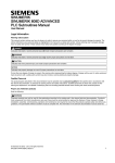
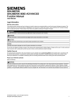
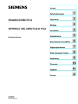
System configuration
The following configuration shows a typical example of the SINUMERIK 808D ADVANCED M controller with the SINAMICS
V70 servo system. Note that the devices with an asterisk ("*") are not included in the scope of delivery.
1), 2): For detailed information on cable shield connection, refer to Section "Analog spindle interface - X54, spindle encoder
interface - X60 (Page 51)".
3): For detailed information on cable shield connection, refer to Section "Connecting the drive and motor (Page 67)".
14
Commissioning Manual
6FC5397-4EP10-0BA4, 08/2015
CAUTION
Personal injury and damage to property from inadequate protection
Inadequate protection may cause minor personal injury or damage to property.
• Using a copper protective earth conductor with a cross section of 10 mm2 to connect the PE terminal of V70 to the
protective earth. For the NC and 24 VDC power supply, there are no special requirements of the cross section of the
copper protective earth conductor. For the inverter or servo spindle drive, it is recommended to refer to the relevant
specifications to confirm the cross section of the copper protective earth conductor.
• Terminals for equipotential bondings that exist in addition to terminals for PE conductors must not be used for loopingthrough the PE conductors.
• To ensure protective separation, an isolating transformer must be used for the 380 VAC line supply system.
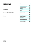
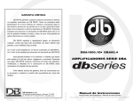
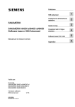
Cabinet grounding guide
Note that the PE/PEN busbar in the cabinet must connect to the ground through a grounding cable with a cross section ≥
10 mm2 as illustrated below.
Commissioning Manual
6FC5397-4EP10-0BA4, 08/2015
15
2.2
PPU and MCP
Components in the panel processing unit (PPU) package
Component
Quantity (pieces)
Illustration
Order number
PPU
(PPU161.2/PP
U160.2)
1
Horizontal
variant
(PPU161.2)
Turning
6FC5370-2AT02-0AA0 (English)
Milling
6FC5370-2AM02-0AA0 (English)
6FC5370-2AT02-0CA0 (Chinese)
6FC5370-2AM02-0CA0 (Chinese)
Vertical variant
(PPU160.2)
Turning
6FC5370-2BT02-0AA0 (English)
6FC5370-2BT02-0CA0 (Chinese)
Milling
6FC5370-2BM02-0AA0 (English)
6FC5370-2BM02-0CA0 (Chinese)
6FC5548-0BA21-0AA0
Drive Bus terminator
1
Mounting
clamps with
screws
•
•
PPU161.2: 8
PPU160.2: 10
Connectors
•
•
I/O connectors: 7
24 V power input connector: 1
User documentation
1
SINUMERIK 808D ADVANCED Operating and Programming - Turning (Chinese)
SINUMERIK 808D ADVANCED Operating and Programming - Milling (Chinese)
Components in the machine control panel (MCP) package
Component
Quantity (pieces)
Illustration
MCP
1
Horizontal MCP
Order number
6FC5303-0AF35-0AA0 (English)
6FC5303-0AF35-0CA0 (Chinese)
Vertical MCP, with an
override switch for the
spindle
Vertical MCP, with a
reserved slot for the
handwheel
6FC5303-0AF35-2AA0 (English)
6FC5303-0AF35-2CA0 (Chinese)
6FC5303-0AF35-3AA0 (English)
6FC5303-0AF35-3CA0 (Chinese)
MCP connection 1 (for connecting
cable
the MCP to the
PPU)
Mounting
clamps with
screws
16
•
•
Horizontal
MCP: 6
Vertical
MCP: 8
Commissioning Manual
6FC5397-4EP10-0BA4, 08/2015
Component
Quantity (pieces)
Pre-printed
MCP strip, Milling
1
Blank strip paper, A4 size
1
User documentation
1
2.3
Illustration
Order number
Product Information for the MCP
Drives and motors
Components in the drive package
Component
Quantity (pieces)
SINAMICS V70
drive
1
Illustration
Outline dimension (Width x
Height x Depth,
mm)
Frame
size 1)
Rated output
current (A)
Order number
80 x 180 x 200
FSA
1.2
6SL3210-5DE12-4UA0
3.0
6SL3210-5DE13-5UA0
100 x 180 x 220
FSB
4.6
6SL3210-5DE16-0UA0
5.3
6SL3210-5DE17-8UA0
7.8
6SL3210-5DE21-0UA0
11.0
6SL3210-5DE21-4UA0
13.2
6SL3210-5DE21-8UA0
140 x 260 x 240
Shielding plate
1
FSC
FSA:
FSB/FSC:
Cable clamp
(FSB and FSC
only)
1
Connectors
•
•
User documentation
1
1)
FSA: 4
FSB/FSC: 2
Safety Instructions
For more information about the different fame sizes, see Section "Drill patterns and outline dimensions (Page 32)".
Commissioning Manual
6FC5397-4EP10-0BA4, 08/2015
17
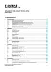
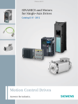
Drive rating plate
Explanation of drive order numbers
Data position of the order
number
Order number
1
2
3
4
5
6
7
8
9
10
11
12
6
S
L
3
2
1
0
5
D
●
❑
❑
0.4 kW
0.75 kW/1 kW
1
1
2
3
4
5
1.5 kW
1.75 kW
2 kW/2.5 kW
1
1
2
6
7
1
0
8
0
3.5 kW
5 kW/7 kW
2
2
1
1
4
8
-
Mains voltage: 3 AC 380 V
to 480 V
-
13
14
15
16
❑
U
A
0
E
Motor output power
Components in the motor package
Component
SIMOTICS S-1FL6
motor
Illustration
Shaft height (mm)
Stall torque (Nm)
Order number 1)
45
1.9
3.5
1FL6042-1AF61-0❑❑1
1FL6044-1AF61-0❑❑1
65
4
6
8
1FL6061-1AC61-0❑❑1
1FL6062-1AC61-0❑❑1
1FL6064-1AC61-0❑❑1
11
15
15
22
1FL6066-1AC61-0❑❑1
1FL6067-1AC61-0❑❑1
1FL6090-1AC61-0❑❑1
1FL6092-1AC61-0❑❑1
30
40
1FL6094-1AC61-0❑❑1
1FL6096-1AC61-0❑❑1
90
User documentation
1)
18
SIMOTICS S-1FL6 Servo Motors Installation Guide
For more information about order numbers, see motor order number explanation described later in this section.
Commissioning Manual
6FC5397-4EP10-0BA4, 08/2015
Motor rating plate
①
②
③
④
⑤
⑥
⑦
⑧
⑨
⑩
⑪
⑫
Motor type
Order number
Serial number
Rated torque
Stall torque
Rated voltage
⑬
⑭
⑮
⑯
⑰
⑱
Rated power
Encoder type and resolution
Thermal class
Degree of protection
Motor operating mode
Stall current
Rated current
Holding brake
Motor ID
Weight
Maximum speed
Rated speed
Explanation of motor order numbers
Data position of the order
number
1
2
3
4
5
6
7
Order number
1
F
L
6
❑
❑
❑
45 mm
0
4
65 mm
0
6
90 mm
0
9
-
8
9
10
11
12
●
●
❑
●
●
-
13
14
15
16
●
❑
❑
●
Shaft height
Stall torque
15 Nm, SH90
0
4 Nm, SH65
1
1.9 Nm, SH45;
2
6 Nm, SH65;
22 Nm, SH90
3.5 Nm, SH45;
4
8 Nm, SH65;
30 Nm, SH90
11 Nm, SH65;
6
40 Nm, SH90
15 Nm, SH65
High inertia variant
Natural cooling
Commissioning Manual
6FC5397-4EP10-0BA4, 08/2015
7
1
A
19
Rated speed
2000 rpm
C
3000 rpm
F
400 V supply voltage
6
IM B5, flange mounting
1
Straight connectors with a
fixed outlet direction
0
Encoder type
Incremental encoder, 2500
ppr
A
Absolute encoder, 20 bit
single turn + 12 bit multi-turn
L
Mechanics
Plain shaft, without brake
G
Plain shaft, with brake
H
Shaft with key, without brake
A
Shaft with key, with brake
B
Protection level IP65, with a
shaft oil seal
1
Device combination
The table below lists ordering data of drives and configurable motors. You can select the desired servo drive according to
the motor configured:
SIMOTICS S-1FL6 servo motor
SINAMICS V70 servo drive
Stall torque
(Nm)
Rated speed
(rpm)
Shaft height
(mm)
Order number
Order number
Frame size
1.9
3,000
45
1FL6042-1AF61-0❑❑1
6SL3210-5DE12-4UA0
FSA
1FL6044-1AF61-0❑❑1
6SL3210-5DE13-5UA0
2,000
65
1FL6061-1AC61-0❑❑1
6SL3210-5DE13-5UA0
1FL6062-1AC61-0❑❑1
6SL3210-5DE13-5UA0
8
1FL6064-1AC61-0❑❑1
6SL3210-5DE16-0UA0
11
1FL6066-1AC61-0❑❑1
6SL3210-5DE17-8UA0
15
1FL6067-1AC61-0❑❑1
6SL3210-5DE21-0UA0
3.5
4
6
15
1FL6090-1AC61-0❑❑1
6SL3210-5DE21-0UA0
22
1FL6092-1AC61-0❑❑1
6SL3210-5DE21-4UA0
30
1FL6094-1AC61-0❑❑1
6SL3210-5DE21-8UA0
40
1FL6096-1AC61-0❑❑1
6SL3210-5DE21-8UA0
20
2,000
90
FSB
FSC
Commissioning Manual
6FC5397-4EP10-0BA4, 08/2015
2.4
Cables
Component
Used for
Order number
Length (m)
Drive Bus cable
PPU to SINAMICS V70 drive
6FC5548-0BA20-1AA2
0.25
6FC5548-0BA20-1AA3
0.35
6FC5548-0BA20-1AD0
3
6FC5548-0BA20-1AF0
5
6FC5548-0BA20-1AH0
7
6FC5548-0BA20-1BA0
10
Drive Bus trailing cable
Spindle setpoint cable
MOTION-CONNECT 300 power cable
MOTION-CONNECT 300 incremental
encoder cable
Commissioning Manual
6FC5397-4EP10-0BA4, 08/2015
15
6FC5548-0BA20-1CA0
20
6FC5548-0BA21-1AD0
3
6FC5548-0BA21-1AF0
5
6FC5548-0BA21-1AH0
7
6FC5548-0BA21-1BA0
10
6FC5548-0BA21-1BF0
15
6FC5548-0BA21-1CA0
20
6FC5548-0BA05-1AD0
PPU (analog spindle interface)
to Siemens inverter or third-party 6FC5548-0BA05-1AE0
drive (with analog input)
6FC5548-0BA05-1AF0
3
6FC5548-0BA05-1AH0
7
6FC5548-0BA05-1BA0
10
SINAMICS V70 FSA to motor
SINAMICS V70 FSB/FSC to
motor
MOTION-CONNECT 300 brake cable
6FC5548-0BA20-1BF0
SINAMICS V70 to motor holding
brake interface
SINAMICS V70 to incremental
encoder interface of the motor
4
5
6FC5548-0BA05-1BF0
15
6FC5548-0BA05-1CA0
20
6FX3002-5CL01-1AD0
3
6FX3002-5CL01-1AF0
5
6FX3002-5CL01-1AH0
7
6FX3002-5CL01-1BA0
10
6FX3002-5CL01-1BF0
15
6FX3002-5CL01-1CA0
20
6FX3002-5CL11-1AD0
3
6FX3002-5CL11-1AF0
5
6FX3002-5CL11-1AH0
7
6FX3002-5CL11-1BA0
10
6FX3002-5CL11-1BF0
15
6FX3002-5CL11-1CA0
20
6FX3002-5BL02-1AD0
3
6FX3002-5BL02-1AF0
5
6FX3002-5BL02-1AH0
7
6FX3002-5BL02-1BA0
10
6FX3002-5BL02-1BF0
15
6FX3002-5BL02-1CA0
20
6FX3002-2CT10-1AD0
3
6FX3002-2CT10-1AF0
5
6FX3002-2CT10-1AH0
7
6FX3002-2CT10-1BA0
10
6FX3002-2CT10-1BF0
15
6FX3002-2CT10-1CA0
20
21
Component
Used for
Order number
Length (m)
MOTION-CONNECT 300 absolute encoder cable
SINAMICS V70 to absolute
encoder interface of the motor
6FX3002-2DB10-1AD0
3
6FX3002-2DB10-1AF0
5
6FX3002-2DB10-1AH0
7
6FX3002-2DB10-1BA0
10
6FX3002-2DB10-1BF0
15
6FX3002-2DB10-1CA0
20
Note
The MOTION-CONNECT 300 cable, spindle setpoint cable, and Drive Bus trailing cable given above are suitable for use in
drag chains. For more information on how to lay cables properly in drag chains, see Section "Notes on the laying of cables in
drag chains (Page 40)".
2.5
Options
External 24 VDC power supply
A 24 VDC power supply is used to supply the 808D ADVANCED and V70 servo drive. Consider the following technical
specification requirements when selecting a 24 VDC power supply:
● 24 VDC supplying the SINUMERIK 808D ADVANCED:
–
Rated input voltage: 24 V
–
Max. input voltage: 28.8 V
–
Min. input voltage without output derating: 20.4 V
–
Rated input current: 2.25 A
● 24 VDC supplying the SINAMICS V70 drive:
Without a holding brake
With a holding brake
Rated voltage (V)
Maximum current (A)
Rated voltage (V)
24 (-15% to +20%)
1
24 (-10% to +10%)
Maximum current (A)
1)
3
The minimum voltage of 24 VDC -10% must be available at the connector on the motor side in order to guarantee
that the brake reliably opens. If the maximum voltage of 24 VDC +10% is exceeded, then the brake could re-close.
The voltage drop along the brake feeder cable must be taken into consideration. The voltage drop ΔU for copper cables can be approximately calculated as follows:
ΔU [V] = 0.042 ∙ (l/q) ∙ IBrake
Where: l = Cable length [m], q = Brake core cross section [mm2], IBrake = DC current of brake [A]
1)
Fuse/circuit breaker
The fuse/circuit breaker is used to protect the control system. Refer to the table below for the selection of fuses and circuit
breakers:
SINAMICS V70
Standard fuse
Circuit breaker
Frame size
Order number
Rated current (A)
Order number
Order number
FSA
6SL3210-5DE12-4UA0
6
3NA3 801-6
3RV 1021-1DA10
6SL3210-5DE13-5UA0
10
3NA3 803-6
3RV 1021-1FA10
6SL3210-5DE16-0UA0
10
3NA3 803-6
3RV 1021-1JA10
6SL3210-5DE17-8UA0
16
3NA3 805-6
3RV 1021-1JA10
6SL3210-5DE21-0UA0
16
3NA3 805-6
3RV 1021-4AA10
6SL3210-5DE21-4UA0
20
3NA3 807-6
3RV 1021-4BA10
6SL3210-5DE21-8UA0
25
3NA3 810-6
3RV 1021-4DA10
FSB
FSC
22
Commissioning Manual
6FC5397-4EP10-0BA4, 08/2015
Braking resistor
A braking resistor is used for the SINAMICS V70. When the internal braking resistor cannot meet the braking requirements,
an external braking resistor can be used to "dump" the regenerative energy produced by the motor, thus giving greatly
improved braking and deceleration capabilities. Select a standard braking resistor according to the table below:
Frame size
Illustration
Resistance (Ω)
Max. power (kW)
Rated power (W)
Max. energy (kJ)
FSA
160
4
100
8
FSB
70
9.1
229
18.3
FSC
27
23.7
1185
189.6
Filter
Siemens recommends you to use a filter to protect the system from high frequency noise.
The table below lists all the filters recommended by Siemens:
Frame size
Illustration
Rated current (A)
Protection class
Order number
FSA
5
IP20
6SL3203-0BE15-0VA0
FSB
12
IP20
6SL3203-0BE21-2VA0
FSC
20
IP20
6SL3203-0BE22-0VA0
Outline dimensions
Rated current W
(A)
D
W2
H1
H
H2
W1
Ø1
Screw
5
55
130
38
158
170
145
8.5
5
M6
12
75
140
58
158
170
145
8.5
5
M6
20
60
130
40
240
250
220
10
5.5
M6
Commissioning Manual
6FC5397-4EP10-0BA4, 08/2015
23
Basic technical data
Rated current
5A
12 A
Rated voltage
3-phase 380 VAC to 480 VAC (-15% to +10%)
Line frequency
50/60 Hz (-10% to +10%)
Product standard
IEC 61800-5-1
20 A
Insertion loss
Rated current
5A
12 A
20 A
Noise frequency
(MHz)
0.1
5
0.5
1.0
5.0
10
30
0.1
5
0.5
1.0
5.0
10
30
0.1
5
0.5
1.0
5.0
10
30
CM (dB)
60
65
55
45
35
20
60
70
70
55
45
15
60
60
60
55
35
15
DM (dB)
50
60
55
50
50
40
60
65
60
50
45
30
40
55
55
50
45
30
Connecting
The figure below provides a connection example. It shows how to connect a line filter to a SINAMICS V70 drive.
SD card
An SD card can be used to copy drive parameters or perform a firmware update. You are recommended to use the Siemens
SD card (order number: 6ES7954-8LB01-0AA0).
You can also select other high quality SD cards with a maximum capacity of 2 GB from manufacturers such as KINGMAX,
Kingston or SanDisk, which are not tested by Siemens.
24
Commissioning Manual
6FC5397-4EP10-0BA4, 08/2015
Toolbox DVD
Under the Toolbox DVD root directory, it contains a file setup.exe. After starting this file the program guides you installing the
following software to the PC:
● SinuComPCIN
–
SinuComPCIN is a tool that allows the commissioning engineer to exchange files between the PC and the control
through RS232 interface.
● Access MyMachine
–
Access MyMachine (AMM) is a tool that allows the commissioning engineer to exchange files between the PC and
the control very easily through the Ethernet interface. For data transmission, the control can be connected to the PC
directly or via the local network.
● PLC Programming Tool
–
PLC Programming Tool makes a connection between the programming tool and the control system. The
commissioning engineer can program and debug the PLC inside the SINUMERIK 808D ADVANCED.
● Config DATA
–
Config_DATA contains the configuration data setup. The setup will install the configuration data for SINUMERIK
808D ADVANCED to your PC. The configuration data consist of the Siemens examples, and the user documents.
Note
For more information about the connection of the filter, fuse/circuit breaker, and braking resistor, see Section "Connecting
the drive and motor (Page 67).
Note
Non-Siemens products
This document contains recommendations relating to non-Siemens products. The fundamental suitability of the nonSiemens products is familiar to us. It goes without saying that equivalent products from other manufacturers may be used.
Our recommendations are to be seen as helpful information, not as requirements or dictates. We cannot accept any liability
for the quality and properties/features of non-Siemens products.
3
Mounting
DANGER
Danger to life when live parts are touched
Death or serious injury can result when live parts are touched.
• Only work on electrical devices when you are qualified for this job.
• Always observe the country-specific safety rules.
Before installing or removing the components of the control system, make sure that the system is disconnected
from the mains.
DANGER
Death or serious injury from fire or electric shock
If the equipment operates in an area subject to inflammables or combustibles, water or corrosion hazards, it
contains high risk of fire or electric shock.
The fire or electric shock may lead to death or serious injury.
Make sure that the control system is installed in a control cabinet with an adequate protection class.
Note
When dimensioning the control cabinet, make sure that the installed components do not exceed the permissible surrounding
air temperature, even if the outside temperature is high.
Commissioning Manual
6FC5397-4EP10-0BA4, 08/2015
25
3.1
Mounting the PPU and MCP
Cut-out dimensions and mounting clearance (mm)
To make maintenance easy, keep sufficient clearance (recommended distance: 80 mm) between the maintenance door on
the PPU and the cabinet wall. The recommended depth of the cabinet is greater than 155 mm.
Horizontal PPU and MCP
Vertical PPU and MCP
26
Commissioning Manual
6FC5397-4EP10-0BA4, 08/2015
Note
Make sure there is enough space around the PPU and the MCP for tightening the screws in the control cabinet.
Note
All vertical MCP versions share the same requirements for cut-out dimensions and mounting clearance. The illustration
above takes the MCP with a reserved slot for the handwheel for example.
Note
When mounting a horizontal PPU together with a vertical MCP or vice versa, follow the requirement for the clearance
between a vertical PPU and a vertical MCP shown above.
Outline dimensions (mm)
PPU161.2
PPU160.2
Commissioning Manual
6FC5397-4EP10-0BA4, 08/2015
27
Horizontal MCP
Vertical MCP (Example: MCP variant with an override switch for the spindle)
Note
All vertical MCP versions have the same outline dimensions.
28
Commissioning Manual
6FC5397-4EP10-0BA4, 08/2015
Mounting the PPU and MCP with the companion clamps
Use the companion clamps (8 for PPU161.2, 10 for PPU160.2, 6 for the horizontal MCP, and 8 for the vertical MCP) to fix
the PPU and MCP to the cabinet panel. You can find the mounting position marks (black triangles) on the back of the PPU
and MCP. See the mounting illustration below:
The following figures show all mounting position marks on the back of the PPU and the MCP. They also show distances
between a clamp and the edge of the PPU or MCP and between two holes of a clamp to make a hole for fixing the screw of
a clamp.
Horizontal PPU and MCP
Commissioning Manual
6FC5397-4EP10-0BA4, 08/2015
29
Vertical PPU and MCP
Note
The clamp mounting position marks on the back of all vertical MCP versions are the same. The figure above takes the MCP
version with a reserved slot for the handwheel for example.
30
Commissioning Manual
6FC5397-4EP10-0BA4, 08/2015
3.2
Mounting the drive
WARNING
Death or severe personal injury from harsh installation environment
A harsh installation environment will jeopardize personal safety and equipment. Therefore,
• Do not install the drive and the motor in an area subject to inflammables or combustibles, water or corrosion hazards.
• Do not install the drive and the motor in an area where it is likely to be exposed to constant vibrations or physical
shocks.
• Do not keep the drive exposed to strong electro-magnetic interference.
WARNING
Hot surface
During operation and for a short time after switching-off the drive, the surfaces of the drive can reach a high
temperature. Avoid coming into direct contact with the drive surface.
Note
For mounting conditions, see Section "Technical data -servo drives".
3.2.1
Mounting orientation and clearance
Mount the drive vertically to the back plate of a shielded cabinet (non-painted) and observe the mounting clearances
specified in the illustration below:
Commissioning Manual
6FC5397-4EP10-0BA4, 08/2015
31
3.2.2
Drill patterns and outline dimensions
Frame size A (unit: mm)
Frame size B (unit: mm)
32
Commissioning Manual
6FC5397-4EP10-0BA4, 08/2015
Frame size C (unit: mm)
3.2.3
Mounting the drive
Note
EMC instructions
• To comply with the EMC standards, all cables connected with the SINAMICS V70 system must be shielded cables,
which include cables from the line supply to the line filter and from the line filter to the SINAMICS V70 drive.
• The SINAMICS V70 drives have been tested in accordance with the emission requirements of the category of C2
(domestic) environment. The conducted emissions and radiated emissions are in compliance with the standard of EN
55011 and reached Class A.
• In a residential environment, this product can cause high-frequency interferences that may necessitate suppression
measures.
• For a radiated emission test, an external AC filter (between the 380 VAC power supply and the drive) will be used to
meet the EMC requirement and the drive will be installed inside the shielded metallic chamber, other parts of the motion
control system (including the PLC, DC power supply, spindle drive, motor) will be put inside the shielded chamber.
• For a conductive emission test, an external AC filter (between the 380 VAC power supply and the drive) will be used to
meet the EMC requirement.
• For the radiated emission and conductive emission test, the length of the line supply cable between the line filter and the
drive must be shorter than 1 m.
Commissioning Manual
6FC5397-4EP10-0BA4, 08/2015
33
Note
Screw tightening
Make sure you fix the screw to the terminal door of the drive after you have completed the installation work.
3.2.4
Electrical cabinet design
It may be preferable to always use cooling units as this allows the cabinet to be sealed which is the best option for stopping
the entry of contaminants. Within the cabinets it may also be necessary to install fans to ensure the air is circulated and
prevent "hot spots" from forming.
The technical specifications of the individual hardware component will provide details of the power loss measured in Watts.
Calculations are made to see if the cabinet can dissipate the heat naturally.
The cabinet manufacturer can supply details of the heat-loss of the cabinet.
Natural heat dissipation occurs through the cabinet walls providing the wall is in free air and not against a wall for example.
A general rule is that the energy dissipated is approximately 50 Watts/m² of free cabinet wall assuming a 10 °C temperature
difference between the cabinet and the outside air.
3.2.4.1
Correct installation of fans
For cabinets it is possible that the cooling can be achieved with fans drawing air from the outside via a filter. Natural
convection causes the warm air to exit via a filter.
The fact that air is being drawn directly from the outside means that this system can never be airtight. Having a fan for the
inlet side only ensures that the cabinet is positively pressurized which helps keep contaminants from entering.
It is extremely important that the filters are service regularly to avoid ingress of contaminants and to maintain the efficiency
of the cooling process.
34
Commissioning Manual
6FC5397-4EP10-0BA4, 08/2015
3.2.4.2
Correct installation of cooling units
The cool air should be directed to the bottom of the drive. The natural convection will draw the air through the drives.
The cool air from the cooling unit should not be directed straight onto/into the drives, it should be allowed to mix with the
warmer air already in the cabinet, this will minimise the risk of condensation forming.
Cabinet top mounted cooling units require a method of directing the cool air from the cooling unit to the bottom of the drives.
In the case of a door mounted unit it may be necessary to direct the cool air with the use of a baffle.
3.3
Mounting the motor
Note
For more information about the mounting conditions, see Section "Technical data - servo motors".
3.3.1
Mounting orientation and outline dimensions
Mounting orientation
The SIMOTICIS S-1FL6 motor supports flange mounting only and it can be used in the following three types of construction:
Commissioning Manual
6FC5397-4EP10-0BA4, 08/2015
35
Note
When configuring the IM V3 type of construction, pay particular attention to the permissible axial force (weight force of the
drive elements) and the necessary degree of protection.
Motor dimensions
Shaft height 45 mm, with incremental encoder (unit: mm)
Stall torque
k
k1
a
b
b1
1.9 Nm
154.5
201
169.5
15
61.5
3.5 Nm
201.5
248
216.5
Shaft height 45 mm, with absolute encoder (unit: mm)
Stall torque
k
k1
a
b
b1
1.9 Nm
157
203.5
172
15
61.5
3.5 Nm
204
250.5
219
36
Commissioning Manual
6FC5397-4EP10-0BA4, 08/2015
Shaft height 65 mm, with incremental encoder (unit: mm)
Stall torque
k
k1
a
b
b1
4 Nm
148
202.5
163
15
69.5
6 Nm
181
235.5
196
8 Nm
181
235.5
196
11 Nm
214
268.5
229
15 Nm
247
301.5
262
Shaft height 65 mm, with absolute encoder (unit: mm)
Stall torque
k
k1
a
b
b1
4 Nm
151
205.5
166
15
69.5
6 Nm
184
238.5
199
8 Nm
184
238.5
199
11 Nm
217
271.5
232
15 Nm
250
304.5
265
Commissioning Manual
6FC5397-4EP10-0BA4, 08/2015
37
Shaft height 90 mm, with incremental encoder (unit: mm)
Stall torque
k
k1
a
b
b1
15 Nm
189.5
255
210.5
33
98.5
22 Nm
211.5
281
236.5
30 Nm
237.5
307
262.5
40 Nm
289.5
359
314.5
Shaft height 90 mm, with absolute encoder (unit: mm)
Stall torque
k
k1
a
b
b1
15 Nm
197
263
218
33
98.5
22 Nm
223
289
244
30 Nm
249
315
270
40 Nm
301
367
322
38
Commissioning Manual
6FC5397-4EP10-0BA4, 08/2015
3.3.2
Mounting the motor
WARNING
Personal injury and material damage
Some motors, especially the 1FL609❑ are heavy. The excessive weight of the motor should be considered and any
necessary assistance required for mounting should be sought.
Otherwise, the motor can fall down during mounting. This can result in serious personal injury or material damage.
NOTICE
Damage to the motor
If the liquid enters the motor, the motor may be damaged
During motor installation or operation, make sure that no liquid (water, oil, etc.) can penetrate into the motor. Besides,
when installing the motor horizontally, make sure that the cable outlet faces downward to protect the motor from ingress of
oil or water.
NOTICE
Damage to the encoder
Do not exert any shock at the shaft end; otherwise, the encoder may be damaged.
Note
Using the eyebolts
The 1FL609❑ motor (90 mm shaft height) has two M8 screw holes for screwing in two eyebolts. Lift the 1FL609❑ motor only
at the eyebolts.
Eyebolts that have been screwed in must be either tightened or removed after mounting.
To ensure better heat dissipation, install a flange between the machine and the motor. You can install the motor onto the
flange with four screws as shown in the following figure.
Motor
Screw
Recommended flange size (mm)
Tightening torque (Nm) Flange material
1FL604❑
4 x M6
270 x 270 x 10
8
1FL606❑
4 x M8
390 x 390 x 15
20
1FL609❑
4 x M12
420 x 420 x 20
85
Commissioning Manual
6FC5397-4EP10-0BA4, 08/2015
Aluminum alloy
39
3.4
Notes on the laying of cables in drag chains
The MOTION-CONNECT cables between the drive and the motor, and setpoint cables and Drive Bus trailing cables
between the drive and the controller satisfy requirements for use in drag chains.
Observe the following notes when laying these cables in drag chains:
Laying cables separately in the drag chain
•
To ensure a long service life of the drag chain and cable, lay cables made of different materials separately with
separating webs in the drag chain.
•
Fill the webs evenly to ensure that the position of cables does not change during operation.
•
Distribute cables as symmetrically as possible according to their weights and dimensions.
•
Use webs to separate cables with different outer diameters.
•
Keep cables untwisted in the drag chain.
Observing minimum bending radius requirements
•
Cables must be able to move without constraint, especially in the bending radii of the chain.
•
Observe the specified minimum bending radii.
Fixing cables
•
Make sure that cables in the drag chain are unattached and movable.
•
Place the cable fixture in a "dead" zone at each end, suitably far away from each end point of the moving parts.
40
Commissioning Manual
6FC5397-4EP10-0BA4, 08/2015
4
Connecting
NOTICE
Damage to the control system
The high-voltage components have strong interference on 24 VDC power supplies.
If the 24 VDC power supply is not isolated from high-voltage components, the control system may be damaged.
The 24 VDC protective extra-low voltage must be generated as a protective extra-low voltage with safe electrical isolation
(according to IEC 204-1, Section 6.4, PELV), and grounded by with a PELV M signal connection to the central grounding
point of the system.
4.1
Interfaces on the PPU and MCP
NOTICE
Failing to connect PE terminals to the ground will cause safety problems
The PE terminals on the PPU and MCP must be connected to the ground; otherwise, it will cause safety problems and
unexpected system conditions.
Interfaces on the PPU
Legend
Interface
Description
X100, X101, X102
Digital inputs
X200, X201
Digital outputs
X21
FAST I/O
X301, X302
Distributed I/O
X10
Handwheel inputs
PPU back
①
②
③
④
⑤
Commissioning Manual
6FC5397-4EP10-0BA4, 08/2015
41
⑥
⑦
⑧
⑨
⑩
⑪
⑫
⑬
⑭
X60
Spindle encoder interface
X54
Analog spindle interface
X2
RS232 interface
X130
Ethernet interface
X126
Drive Bus interface
X30
USB interface, for connection with the MCP
X1
Power supply interface, +24 VDC power supply
-
Slot for the system CompactFlash Card (CF card)
-
PE terminal, for connection with the ground
-
USB interface
PPU front
⑮
Interfaces on the MCP
Legend
Interface
Description
①
②
③
X10
USB interface, for connection with the PPU
-
PE terminal, for connection with the ground
-
Reserved hole for plastic tie which is used to fix the USB cable connecting the PPU with
the MCP
④
-
Reserved hole for fixing the USB cable connecting the PPU and the MCP
Note
The two kinds of vertical MCP, with a reserved hole for the handwheel and with an override switch for the spindle, have the
same mechanical interfaces design for the USB cable, PE terminal and reserved hole for fixing the USB cable on the back.
The illustration above takes the version with a spindle override switch for example.
42
Commissioning Manual
6FC5397-4EP10-0BA4, 08/2015
4.1.1
Digital input interfaces - X100, X101, X102
Pin assignment
Type
Mini Combicon 10-pin
Cable
Max. length: 10 m
Max. cross-section: 1.5 mm2 (when using one cable per connection)
Inputs
Permissible level (including ripple)
High level: 20.4 V to 28.8 V
Low level: -3 V to +5 V
Pin
X100 (DIN0)
X101 (DIN1)
X102
Remarks
1
N.C.
N.C.
N.C.
Not assigned
2
I0.0
I1.0
I2.0
Digital input
3
I0.1
I1.1
I2.1
Digital input
4
I0.2
I1.2
I2.2
Digital input
5
I0.3
I1.3
I2.3
Digital input
6
I0.4
I1.4
I2.4
Digital input
7
I0.5
I1.5
I2.5
Digital input
8
I0.6
I1.6
I2.6
Digital input
9
I0.7
I1.7
I2.7
Digital input
10
M
M
M
External ground
Connecting according to the default PLC program
Turning
Milling
Note
End sleeves are necessary if you use two cables per connection.
Fasten the cables to the screw terminals and plug the terminals into interfaces X100, X101 and X102 correctly.
Commissioning Manual
6FC5397-4EP10-0BA4, 08/2015
43
4.1.2
Digital output interfaces - X200, X201
Pin assignment
Type
Mini Combicon 10-pin
Cable
Max. length: 10 m
Max. cross-section: 1.5 mm2 (when using one cable per connection)
Outputs
Rated digital output current: 250 mA
Pin
X200 (DOUT0)
X201 (DOUT1)
Remarks
1
+24 V
+24 V
+24 V input (20.4 V to
28.8 V)
2
Q0.0
Q1.0
Digital output
3
Q0.1
Q1.1
Digital output
4
Q0.2
Q1.2
Digital output
5
Q0.3
Q1.3
Digital output
6
Q0.4
Q1.4
Digital output
7
Q0.5
Q1.5
Digital output
8
Q0.6
Q1.6
Digital output
9
Q0.7
Q1.7
Digital output
10
M
M
External ground
Connecting according to the default PLC program
Turning
Milling
Note
End sleeves are necessary if you use two cables per connection.
Fasten the cables to the screw terminals and plug the terminals into interfaces X200, X201 correctly.
44
Commissioning Manual
6FC5397-4EP10-0BA4, 08/2015
4.1.3
Fast input/output - X21
Pin assignment
Type
Mini Combicon 10-pin
Cable
Shielded cable
Max. length: 10 m
Max. cross-section: 1.5 mm2 (when use one cable per connection)
Inputs
Permissible level (including ripple)
High level: 20.4 V to 28.8 V
Illustration
Pin
Signal
Low level: -3 V to +5 V
Comment
1
+24 V
+24 V input (20.4 V to 28.8 V)
2
NCRDY_1
NC ready signal contact 1
3
NCRDY_2
NC ready signal contact 2
4
DI1
Digital input, for connection to probe 1
5
DI2
Digital input, for connection to probe 2
6
BERO_SPINDLE or DI3
Spindle bero or digital input
7
DO1
Fast output
8
CW
Spindle rotating clockwise
9
CCW
Spindle rotating counter-clockwise
10
M
Ground
Connecting
You can connect the fast I/O to the inverter to control the spindle rotating direction (unipolar):
NC readiness is in the form of a relay contact (NO). It must be integrated into an EMERGENCY STOP circuit. The
connection diagram is shown as follows:
1)
When the NC is not ready, the contact is open; otherwise, the contact is closed.
Commissioning Manual
6FC5397-4EP10-0BA4, 08/2015
45
Connection cables
End sleeves are necessary if you use two cables per connection.
Fasten the cables to the screw terminals and plug the terminal into the interface X21.
You can buy the shielded cables from a third-party manufacturer.
Note
To ensure optimum interference immunity, use only the shielded cable to connect the FAST I/O terminals (X21).
4.1.4
Distributed I/O - X301, X302
Pin assignment
Type
50-pin socket
Inputs
Permissible level (including ripple)
High level: 20.4 V to 28.8 V
Low level: -3 V to +5 V
Outputs
Rated digital output current: 250 mA
Pin
Signal
Comment
1
M
External ground
26
I5.7
Digital input
2
+24 V
+24 V output 1)
27
-
Not assigned
3
I3.0
Digital input
28
-
Not assigned
4
I3.1
Digital input
29
-
Not assigned
5
I3.2
Digital input
30
-
Not assigned
6
I3.3
Digital input
31
Q2.0
Digital output
7
I3.4
Digital input
32
Q2.1
Digital output
8
I3.5
Digital input
33
Q2.2
Digital output
9
I3.6
Digital input
34
Q2.3
Digital output
10
I3.7
Digital input
35
Q2.4
Digital output
11
I4.0
Digital input
36
Q2.5
Digital output
12
I4.1
Digital input
37
Q2.6
Digital output
13
I4.2
Digital input
38
Q2.7
Digital output
14
I4.3
Digital input
39
Q3.0
Digital output
15
I4.4
Digital input
40
Q3.1
Digital output
16
I4.5
Digital input
41
Q3.2
Digital output
17
I4.6
Digital input
42
Q3.3
Digital output
18
I4.7
Digital input
43
Q3.4
Digital output
19
I5.0
Digital input
44
Q3.5
Digital output
20
I5.1
Digital input
45
Q3.6
Digital output
21
I5.2
Digital input
46
Q3.7
Digital output
22
I5.3
Digital input
47
+24 V
+24 V input
23
I5.4
Digital input
48
+24 V
+24 V input
24
I5.5
Digital input
49
+24 V
+24 V input
25
I5.6
Digital input
50
+24 V
+24 V input
46
Pin
Signal
Comment
Commissioning Manual
6FC5397-4EP10-0BA4, 08/2015
Pin
Signal
Comment
Pin
Signal
1
M
External ground
26
I8.7
Digital input
2
+24 V
+24 V output
27
-
Not assigned
3
I6.0
Digital input
28
-
Not assigned
4
I6.1
Digital input
29
-
Not assigned
5
I6.2
Digital input
30
-
Not assigned
6
I6.3
Digital input
31
Q4.0
Digital output
7
I6.4
Digital input
32
Q4.1
Digital output
8
I6.5
Digital input
33
Q4.2
Digital output
9
I6.6
Digital input
34
Q4.3
Digital output
10
I6.7
Digital input
35
Q4.4
Digital output
11
I7.0
Digital input
36
Q4.5
Digital output
12
I7.1
Digital input
37
Q4.6
Digital output
13
I7.2
Digital input
38
Q4.7
Digital output
14
I7.3
Digital input
39
Q5.0
Digital output
15
I7.4
Digital input
40
Q5.1
Digital output
16
I7.5
Digital input
41
Q5.2
Digital output
17
I7.6
Digital input
42
Q5.3
Digital output
18
I7.7
Digital input
43
Q5.4
Digital output
19
I8.0
Digital input
44
Q5.5
Digital output
20
I8.1
Digital input
45
Q5.6
Digital output
21
I8.2
Digital input
46
Q5.7
Digital output
22
I8.3
Digital input
47
+24 V
+24 V input
23
I8.4
Digital input
48
+24 V
+24 V input
24
I8.5
Digital input
49
+24 V
+24 V input
25
I8.6
Digital input
50
+24 V
+24 V input
1)
Comment
1) Make sure that the current at pin 2 of X301 or X302 does not exceed the maximum current Iout = 0.25 A; otherwise, the
controller could be damaged.
Connecting
DANGER
The 24 V power supply must be protective extra-low voltage in accordance with EN60204-1, Section 6.4, PELV (with M
ground).
CAUTION
Be sure not to connect the pin 2 of X301/302 to ground; otherwise, the CNC controller of the power supply could be
damaged!
Note
The 24 V output of X301/302 pin 2 comes from pins 47 to 50.
Commissioning Manual
6FC5397-4EP10-0BA4, 08/2015
47
Note
Addressing ranges
X301: IB3, IB4, IB5, QB2, QB3
X302: IB6, IB7, IB8, QB4, QB5
Note
The connecting cable between the power source, load current supply connection, and associated reference potential M must
not exceed the maximum permissible length of 10 m.
Digital inputs
The diagram below shows you how to connect the connector pins of the digital inputs at interface X301 (example). You can
connect connector X302 in the same way.
Note
When using an external power supply, you must connect the 24 V (permissible range: 20.4 V to 28.8 V) power supply for the
digital outputs to all the four power input pins (X301, X302: pins 47, 48, 49, 50).
Digital outputs
The diagram below shows you how to connect the connector pins of the digital outputs at interface X301 (example). You can
connect connector X302 in the same way.
To supply the digital outputs, you must connect an external 24 VDC power supply (X301, X302: pins 47, 48, 49, 50).
48
Commissioning Manual
6FC5397-4EP10-0BA4, 08/2015
You must also connect the reference ground of the external power supply to X301, X302: Pin 1 (M).
CAUTION
You must ensure that the max. current consumption at pin 47, pin 48, pin 49 or pin 50 does not exceed 1 A.
Note
You must connect the 24 V power supply for the digital outputs to all the four power input pins (X301, X302: pins 47, 48, 49,
50).
External power supply
When using an external power supply for the digital inputs, you must connect the reference ground to X301, X302: Pin 1 (M).
Connecting according to the default PLC program
The control system has integrated with a default PLC application. If you perform the commissioning work with the default
PLC application, arrange wiring as follows.
4.1.5
Handwheel inputs - X10
Pin assignment
Type
Mini Combicon 10-pin
Cable
Max. length: 3 m
Illustration
Commissioning Manual
6FC5397-4EP10-0BA4, 08/2015
Pin
Signal
Comment
1
1A
Track A, handwheel 1
2
-1A
Negative Track A, handwheel 1
3
1B
Track B, handwheel 1
4
-1B
Negative Track B, handwheel 1
5
+5 V
+5 V power output
6
M
Ground
7
2A
Track A, handwheel 2
8
-2A
Negative Track A, handwheel 2
9
2B
Track B, handwheel 2
10
-2B
Negative Track B, handwheel 2
49
Connecting
You are allowed to connect at most two electronic handwheels at connector X10 on the PPU.
The handwheels must meet the following requirements:
Transmission procedure
5 V square wave signals (TTL level or RS422)
Signals
Track A as a true and negative signal (Ua1Ua1)
Track B as a true and negative signal (Ua2Ua2)
Max. input frequency
500 kHz
Phase shift between Track A to Track B
90o ± 30o
Supply
5 V, max. 250 mA
4.1.6
Drive Bus interface - X126
Pin assignment
Type
IEEE 1394, 6-pin, female
Cable
Type: Drive Bus cable/Drive Bus trailing cable
Max. length: 20 m
Illustration
Pin
Signal
Comment
1
PB_N
Negative RxD/TxD of Drive Bus
2
1P5
+5 V
3
PB
Positive RxD/TxD of Drive Bus
4
NULL
Not connected
5
PB_RTS
Request to send
6
1M5
Ground
Connecting
Drive Bus interfaces on the SINAMICS V70 - X10, X11
Illustration
50
Pin No.
Signal
Description
1
A
Differential signal A
2
P5PB
+5V
3
B
Differential signal B
4
NC
Not assigned
5
RTS
Request to send
6
MPB
0V
Commissioning Manual
6FC5397-4EP10-0BA4, 08/2015
Connecting example
Note
You must install the Drive Bus terminator (that ships with the PPU) on X11 of the last servo drive; otherwise, the servo
system cannot work properly.
4.1.7
Analog spindle interface - X54, spindle encoder interface - X60
Interface X54 is for connecting the PPU to the inverter or servo spindle drive. Interface X60 is for connecting the PPU to the
spindle encoder.
Pin assignment - X54
Type
Sub-D, 9-pin, female
Cable
Max. length: 10 m
Illustration
Pin
Signal
Comment
1
AO
Analog voltage
2
-
not assigned
3
-
not assigned
4
-
not assigned
5
SE1
Analog drive enable (contact: electrically isolated n.o. contact)
6
SE2
Analog drive enable (contact: electrically isolated n.o. contact)
7
-
not assigned
8
-
not assigned
9
AGND
Ground
Commissioning Manual
6FC5397-4EP10-0BA4, 08/2015
51
Pin assignment - X60
Type
Sub-D, 15-pin, female
Cable
Type: encoder cable
Max. length: 10 m
Illustration
Pin
Signal
Comment
1
2
-
Not assigned
Not assigned
3
4
5
6
+5 V
+5 V
Not assigned
+5 V power supply
Not assigned
+5 V power supply
7
8
9
M
M
Ground
Not assigned
Ground
10
11
12
Z
Z_N
B_N
Zero mark
Zero mark, negative
Track B, negative
13
14
15
B
A_N
A
Track B
Track A, negative
Track A
Connecting
Connecting the inverter or servo spindle drive (unipolar)
1) 10 V analog voltage
2) 0 V signal
3) Use twisted pair cables for signals A/A_N, B/B_N, Z/Z_N, and +5 V/M.
52
Commissioning Manual
6FC5397-4EP10-0BA4, 08/2015
Connecting the inverter or servo spindle drive (bipolar)
1) +/- 10 V analog voltage
2) 0 V signal
3) Use twisted pair cables for signals A/A_N, B/B_N, Z/Z_N, and +5 V/M.
4.1.8
Ethernet interface - X130
Pin assignment
Type
8-pin RJ45 socket
Cable
Type: Ethernet cable
Illustration
Pin
Signal
Comment
1
MX1+
Data 1
2
MX1-
Data 1
3
MX2+
Data 2
4
MX3+
Data 3
5
MX3-
Data 3
6
MX2-
Data 2
7
MX4+
Data 4
8
MX4-
Data 4
Note
The length of the Ethernet cable must be less than 30 m or the communication will be unstable.
Commissioning Manual
6FC5397-4EP10-0BA4, 08/2015
53
4.1.9
RS232 interface - X2
You can connect a PC to the PPU version 161.2/160.2 via an RS232 port to establish communication between the PC and
the control system.
Pin assignment
Type
Sub-D, 9-pin, male
Cable
Type: RS232
Max. length: 10 m
Illustration
Pin
Signal name
Signal type
Comment
1
-
-
Not assigned
2
RxD
I
Receive data
3
TxD
O
Transmit data
4
DTR
O
Data terminal ready
5
M
VO
Ground
6
DSR
I
Request set ready
7
RTS
O
Request to send
8
CTS
I
Clear to send
9
-
-
Not assigned
Note
Use only shielded twisted pair cables; You must connect the cable shield to the metal or metalized connector casing of the
control system.
54
Commissioning Manual
6FC5397-4EP10-0BA4, 08/2015
4.1.10
Power supply interface - X1
The PPU uses a 24 VDC power supply. You can connect the 24 VDC power supply via interface X1. For more information
about the 24 VDC power supply, see Section "Options (Page 22)".
Pin assignment
Type
Combicon 4-pin
Cable
Max. length: 10 m
Illustration
Pin1
Signal
Name
Comment
1
0V
M24
0V
2
24 V
P24
+24 V
3
0V
M24
0V
4
24 V
P24
+24 V
Note:
The 0 V terminals as well as the 24 V terminals are internally connected in parallel. This
means that you can connect the 24 V power supply to either of the terminal pairs.
4.1.11
USB interface on the front cover of the PPU
Pin assignment
Type
USB socket, type A
Cable
Type: USB 1.1 cable
Max. length: 3 m
Illustration
4.1.12
Pin
Signal name
Signal type
Comment
1
P5_USB0
VO
5 V power supply
2
DM_USB0
I/O
USB data-
3
DP_USB0
I/O
USB data+
4
M
VO
Ground
USB interface - X30
There is a USB interface on the back of the PPU. This USB interface is used for connecting with the MCP.
Pin assignment
Type
USB socket, type A Combicon 4-pin
Cable
Type: USB cable (0.5 m)
Illustration
Pin
Signal name
Signal type
Comment
1
P5_USB0
VO
5 V power supply
2
DM_USB0
I/O
USB data-
3
DP_USB0
I/O
USB data+
4
M
VO
Ground
Commissioning Manual
6FC5397-4EP10-0BA4, 08/2015
55
Connecting
The illustration below shows the connection between the PPU and the MCP with the MCP connection cable.
4.1.13
Slot for the system CF card
The system CF card is installed on the PPU at the factory.
①
Maintenance door
②
CF card
Note
The maintenance door is accessible only by the Siemens service personnel.
Do not touch or remove the system CF card under any conditions.
56
Commissioning Manual
6FC5397-4EP10-0BA4, 08/2015
4.2
Interfaces on the SINAMICS V70 servo system
The SINAMICS V70 servo system, consisting of the SINAMICS V70 servo drive and SIMOTICS S-1FL6 servo motor, is an
economical closed-loop servo drive solution for machine tool applications. It is designed to be used with the SINUMERIK
808D ADVANCED controller. The SINAMICS V70 is available in three frame sizes (FS) including FSA, FSB, and FSC.
Interfaces on the SINAMICS V70 FSA (with detachable terminal blocks)
Commissioning Manual
6FC5397-4EP10-0BA4, 08/2015
57
Interfaces on the SINAMICS V70 FSB/FSC (with screw terminals)
Note
For more information about the connection of the X10 and X11, see Section "Drive Bus interface - X126 (Page 50)".
Interfaces on the SIMOTICS S-1FL6 motor
58
Commissioning Manual
6FC5397-4EP10-0BA4, 08/2015
4.2.1
Main circuit wiring
4.2.1.1
Main circuit interfaces
Main circuit interfaces (drive side)
Type
Illustration
Line supply input interface
FSB, FSC
1):
FSA
2):
Signal
Description
Line phase L1
3 phase 380 VAC to 480 VAC
Line phase L2
Line phase L3
Motor power interface
Motor phase U
Connects to the SIMOTICS S1FL6 motor
Motor phase V
Motor phase W
Internal/external braking
resistor interface
Digitally controlled
potentiometer
(DCP)
DCP is connected to R2 at the
factory
Resistor 2 (R2)
Resistor 1 (R1)
Grounding connector
-
For connecting the power supply
grounding connector and the
servo motor grounding connector
Maximum cable cross-section: 2.5 mm2
1)
2)
The screw type for FSB and FSC is M4 and the recommended tightening torque is 2.25 Nm.
The screw type for FSA is M2.5 and the recommended tightening torque is 0.4 Nm to 0.5 Nm.
Main circuit interface (motor side)
Type
Illustration
Power connector
Commissioning Manual
6FC5397-4EP10-0BA4, 08/2015
Signal
Description
1: U
Phase U
2: V
Phase V
3: W
Phase W
4: PE
Protective earthing
59
4.2.1.2
Main circuit wiring
Wiring diagram for SINAMICS V70 main circuit (example):
Note
For more information about the wiring of the external braking resistor, see Section "Connecting an external braking resistor DCP, R1 (Page 65)".
Note
Filter
A line filter is required so that the system can pass the CE certification (radiated emission test or conducted emission test).
Circuit breaker
You can install a circuit breaker to protect the system.
For more information about the order number of Siemens recommended filters and circuit breakers, see Section "Options
(Page 22)".
4.2.2
Connecting the 24 V power supply/STO - X6
Control circuit interfaces - drive side
Type
Illustration
Safe Torque Off (STO) interfaces
Control power input interfaces1)
Maximum connectable cross-section: 1.5 mm2
1)
Maximum current consumption values without a brake power supply and with a brake power supply are respectively 1 A
and 3 A.
For more information about the 24 VDC power supply, see Section "Options (Page 22)".
60
Commissioning Manual
6FC5397-4EP10-0BA4, 08/2015
Wiring
WARNING
Material damages and personal injuries by the drop of a hanging axis
When the servo system is used as a hanging axis, the axis will drop if the positive and negative poles of the 24 V power
supply are connected inversely. Unexpected drop of the hanging axis may cause material damages and personal injuries.
Make sure that the 24 V power supply is correctly connected.
WARNING
Material damages and personal injuries by the drop of a hanging axis
It is not allowed to use the STO with a hanging axis because the axis may drop. Unexpected drop of the hanging axis may
cause material damages and personal injuries.
Note
Using the STO function
The STO1, STO+ and STO2 are short-circuited at the factory.
When the STO function is to be used, you must remove the short-circuit stick before connecting the STO interfaces. The
safety function of the servo drive is SIL 2 (EN61800-5-2). If you do not need to use it any more, you must reinsert the shortcircuit stick. Otherwise, the motor will not run.
The wiring for factory setting and using the STO function is shown as follows:
Commissioning Manual
6FC5397-4EP10-0BA4, 08/2015
61
If you use the STO function with the SINUMERIK 808D ADVANCED control system, perform the wiring as illustrated below:
STO function
In conjunction with a machine function or in the event of a fault, the "Safe Torque Off" (STO) function is used to safely
disconnect the torque-generating energy feed to the motor.
When the function is selected, the drive unit is in a "safe status". The switching on inhibited function prevents the drive unit
from being restarted.
The two-channel pulse suppression function integrated in the module is a basis for this function.
Functional features of "Safe Torque Off"
● This function is integrated in the drive; this means that a higher-level controller is not required.
● The function is drive-specific, i.e. it is available for each drive and must be individually commissioned.
● When the "Safe Torque Off" function is selected, the following applies:
–
The motor cannot be started accidentally.
–
The pulse suppression safely disconnects the torque-generating energy feed to the motor.
–
The power unit and motor are not electrically isolated.
● By selecting/deselecting STO, in addition to the fault messages, the safety messages are also automatically withdrawn.
The STO function can be used wherever the drive naturally reaches a standstill due to load torque or friction in a sufficiently
short time or when "coasting down" of the drive will not have any relevance for safety.
Note
Closing delay of the holding brake
The closing signal (low level) of the holding brake is output 30 ms after the STO is triggered.
Preconditions for using the STO function
When use the STO function, the following preconditions should be fulfilled:
● Each monitoring channel (STO1 and STO2) triggers safe pulse suppression with its switch off signal path.
● If a motor holding brake is connected and configured, the connected brake is not safe because there is no safety function
for brake, such as safe brake.
62
Commissioning Manual
6FC5397-4EP10-0BA4, 08/2015
Behaviors of the STO function
Terminal
State
Action
STO1
STO2
High level
High level
Safe
The servo motor can normally run when you power on the servo
drive.
Low level
Low level
Safe
The servo drive starts up normally but the servo motor cannot run.
High level
Low level
Unsafe
Alarm occurs and servo motor coasts down.
Low level
High level
Unsafe
Alarm occurs and servo motor coasts down.
For more information about the STO function, see the SINUMERIK 808D ADVANCED Function Manual.
4.2.3
Connecting the holding brake - X7
Holding brake (drive side)
Type
Illustration
Brake interfaces
Signal
Description
Phase B+
B+: + 24 V, motor brake voltage positive
Phase B-
B-: 0 V, motor brake voltage negative
Maximum cable cross-section: 1.5 mm2
Input voltage tolerance: 24 V ± 10%
Holding brake (motor side)
Type
Illustration
Brake connector
Signal
Description
1: B+
Phase Brake +
2: B-
Phase Brake -
Wiring
4.2.4
Connecting the encoder - X9
The SINAMICS V70 servo drive supports two types of encoders:
● Incremental encoder
● Absolute encoder
NOTICE
Cable shielding
The encoder cable must be shielded to meet the EMC requirements.
Commissioning Manual
6FC5397-4EP10-0BA4, 08/2015
63
Encoder connector - drive side
14-pin socket connector, incremental/absolute encoder feedback interface X9
Illustration
Pin No.
Signal
Description
1
Biss_DataP
Absolute encoder data signal, positive
2
3
4
Biss_DataN
Biss_ClockN
Biss_ClockP
Absolute encoder data signal, negative
Absolute encoder clock signal, negative
Absolute encoder clock signal, positive
5
6
7
P5V
P5V
M
Encoder power supply, +5V
Encoder power supply, +5V
Encoder power supply, grounding
8
9
10
11
M
Rp
Rn
Bn
Encoder power supply, grounding
Encoder R phase positive signal
Encoder R phase negative signal
Encoder B phase negative signal
12
13
14
Bp
An
Ap
Encoder B phase positive signal
Encoder A phase negative signal
Encoder A phase positive signal
Note
The screw type is UNC 4-40 (plug-in terminal block) and the recommended tightening torque is 0.5 Nm to 0.6 Nm.
Encoder connector - motor side
8-pin connector, incremental encoder and absolute encoder
Illustration
Pin No.
Incremental encoder
Absolute encoder
Signal
Description
Signal
Description
1
2
P_Supply
M
Power supply 5 V
Power supply 0 V
P_Supply
M
Power supply 5 V
Power supply 0 V
3
4
5
A+
AB+
Phase A+
Phase APhase B+
n. c.
Clock_N
Data_P
Not connected
Inverted clock
Data
6
7
8
BR+
R-
Phase BPhase R+
Phase R-
Clock_P
n. c.
Data_N
Clock
Not connected
Inverted data
Wiring
64
Commissioning Manual
6FC5397-4EP10-0BA4, 08/2015
Shielded encoder cable grounding
When making an encoder cable, you should strip the outer insulation sheath for a maximum distance of 3 cm and connect
the cable shield to ground, as shown in the following figure:
4.2.5
Connecting an external braking resistor - DCP, R1
The SINAMICS V70 has been designed with an internal braking resistor to absorb regenerative energy from the motor.
When the internal braking resistor cannot meet the braking requirements, you can connect an external braking resistor. For
more information about the selection of braking resistors, see Section "Options (Page 22)".
Connecting an external braking resistor
NOTICE
Damage to the drive
Before connecting an external resistor to DCP and R1, remove the connection between terminals DCP and R2; otherwise,
the drive may be damaged.
Connect the external braking resistor as follows:
Commissioning Manual
6FC5397-4EP10-0BA4, 08/2015
65
4.3
System connection overview
4.3.1
Connecting the CNC controller
* For the SINUMERIK 808D ADVANCED T control system, connecting to the third and fourth drives is optional and depends
upon whether you activate the software option "additional axis". If you desire to configure the control system to control an
additional linear axis, connect the additional axis to the third or fourth SINAMICS V70 which connects to a servo motor. For
the SINUMERIK 808D ADVANCED M control system, connecting to the fourth drive is optional and depends upon whether
you activate the software option "additional axis". If you desire to configure the control system to control an additional linear
axis, connect the additional axis to the fourth SINAMICS V70 which connects to a servo motor.
66
Commissioning Manual
6FC5397-4EP10-0BA4, 08/2015
4.3.2
Connecting the drive and motor
Connection overview
The connection illustration below shows you a system connection example where the SINUMERIK 808D ADVANCED
controls one drive.
Note
• The line supply cable, Drive Bus cable/Drive Bus trailing cable, power cable, and encoder cable are shielded.
• The part of the line supply cable between the line filter and the drive must be shielded and shorter than 1 m.
• The maximum length for all cables must be shorter than 30 m.
• For more information about the connection of the external braking resistor, see Section "Connecting an external braking
resistor - DCP, R1 (Page 65)".
• For more information about the connection of the STO terminals, see Section "Connecting the 24 V power supply/STO X6 (Page 60)".
Commissioning Manual
6FC5397-4EP10-0BA4, 08/2015
67
WARNING
Personal injury and damage to property from improper connections
Improper connections have high risks of electrical shock and short circuit, which will jeopardize personal safety
and equipment.
• The drive must be directly connected with the motor. It is not permissible to connect a capacitor, inductor or
filter between them.
• The line supply voltage must be within the allowable range (refer to the drive rating plate). Never connect
the line supply cable to the motor terminals U, V, W or connect the motor power cable to the line input
terminals L1, L2, L3.
• Never wire up the U, V, W terminals in an interchanged phase sequence.
• If the CE marking for cables is mandatory in some cases, the motor power cable, line supply cable and
brake cable used must all be shielded cables.
• For terminal box connection, make sure that the clearances between non-insulated live parts are at least
5.5 mm.
• Route signal cables and power cables separately in different cable conduits. The signal cables shall be at
least 10 cm away from the power cables.
• Cables connected may not come into contact with rotating mechanical parts.
Connecting the cable shields with the shielding plate
To achieve EMC-compliant installation of the drive, use the shielding plate that is shipped with the drive to connect the cable
shields. See the following example for steps to connect cable shields with the shielding plate:
68
Commissioning Manual
6FC5397-4EP10-0BA4, 08/2015
WARNING
Danger to life due to fire or electric shock when using unsuitable residual current protection devices
The drive can cause a current to flow in the protective conductor.
This current can cause the residual current device (RCD) or residual current monitoring (RCM) to incorrectly
trip (nuisance trip).
In the case of a fault (ground fault), the fault current can contain a DC component, which prevents the
RCD/RCM from tripping, with the risk of subsequent fault or electric shock.
Use only the type B RCD in the supply system for the SINAMICS V70 drive.
DANGER
Death or severe personal injury from electrical shock
The earth leakage current for the drive can be greater than AC 3.5 mA, which may cause death or severe
personal injury due to electrical shock.
A fixed earth connection is required to eliminate the dangerous leakage current. In addition, the minimum size
of the protective earth conductor shall comply with the local safety regulations for high leakage current
equipment.
Adjusting cable orientations from the motor side
From the motor side, you can adjust the orientation of the power cable, encoder cable, and brake cable to facilitate cable
connection.
Note
Rotating the connectors
All the three motor-side connectors can be rotated only within 360°.
Commissioning Manual
6FC5397-4EP10-0BA4, 08/2015
69
5
Toolbox software
5.1
Installing the software tools
Software components
In order to integrate the control system into a machine tool, software tools are required. These tools, including service tools
are supplied on a DVD. The DVD is called the Toolbox DVD and is provided at delivery.
The following software tools are included on the Toolbox DVD:
Software
Description
See-also
AccessMyMachine
(AMM)
AMM is a multifunctional tool used for data transfer, service, commissioning tasks and remote
control.
AMM communication tool (Page 287)
PLC Programming Tool The tool provides a user-friendly environment for
PLC Programming Tool (Page 181)
commissioning the PLC. With this tool, you can
develop, edit, and observe the logic to control your
applications.
SinuComPCIN
SinuComPCIN is a tool that allows you to transfer
data between the PC and the control system
through RS232 interface.
For more information, see Section "Executing/transferring a part program through the
RS232 interface" in the SINUEMRIK 808D
ADVANCED Programming and Operating
Manual (Turning)/(Milling).
Config DATA
Config DATA contains some PLC example files
including default PLC programs for turning/milling
machines.
-
Supported operating systems
The software tools above support the following operating systems:
● Windows Vista (both 32-bit and 64-bit versions)
● Windows 7 (both 32-bit and 64-bit versions)
Installing the software
To install the software on your PC, proceed through the following steps:
1. Double-click the "Setup.exe" in the folder.
70
Commissioning Manual
6FC5397-4EP10-0BA4, 08/2015
2. Read the welcome information and continue with "Next".
3. You can click the "Readme" button to read the indication information then close it and continue with "Next" or you can
skip the reading and click "Next" directly.
4. Accept the software license agreement and continue with "Next".
Commissioning Manual
6FC5397-4EP10-0BA4, 08/2015
71
5. Select desired languages you want to install.
6. If you have installed an earlier version of a program, un-install the program first, then start the installation again and
select the required software from the list.
7. During the installation, various dialog boxes will appear. Acknowledge the dialog boxes and enter and confirm the
installation information where necessary. Installing all the software packages will take approximately 30 minutes. When
the installation finishes, shortcuts will be created on the desktop.
72
Commissioning Manual
6FC5397-4EP10-0BA4, 08/2015
5.2
Overview of PLC Programming Tool
In order to edit the PLC program, use PLC Programming Tool V3.2.4 or higher.
By using PLC Programming Tool, you can perform the following operations:
● Creating the PLC program
● Editing the PLC program
● Making a connection between the programming tool and the system
● Compiling the PLC program
● Downloading the PLC program
● Uploading the PLC program
● Monitoring the PLC
PLC instructions
Various instructions are available in PLC Programming Tool. You can view them in the instruction branch of the instruction
tree.
Commissioning Manual
6FC5397-4EP10-0BA4, 08/2015
73
You can right-click an instruction or directly press the F1 key to view its help information.
The address of each instruction can be edited at any time by highlighting the instruction.
Data management
The data can be broken down into three areas:
● Non-retentive data
● Retentive data
● Machine data for the PLC (all active at POWER ON)
Most data, such as the process image, timer, and counter, is non-retentive and cleared each time the control system is
restarted.
For the retentive data, there is a data range of 1400 0000 to 1400 0127. This location can be used to save all the data which
is to remain valid after POWER OFF/ON.
With the aid of the PLC machine data (see the user interface), you can pre-assign your program with data or parameterize
various parts of the program.
Program organization
During the PLC programming, you must structure your program into finished program parts (subroutines). The programming
language for the S7-200 offers you the capability to set up your user program in a structured manner.
There are the following two types of programs:
● Main program
● Subroutine
Eight levels of programming are possible.
74
Commissioning Manual
6FC5397-4EP10-0BA4, 08/2015
6
Initial commissioning
NOTICE
Plugging or unplugging the SD card will cause startup failure.
Do not plug or unplug the SD card during startup; otherwise, the drive will fail to start up.
NOTICE
Firmware damage due to drive power-off during data transfer
Switching off the 24 VDC power supply for the drive during data transfer from the SD card to the drive can cause damage
to the drive firmware.
• Do not switch off the drive power supply when the data transfer from the SD card to the drive is in process.
NOTICE
Existing setting data may be overwritten by the setting data on the SD card during startup.
• When a drive is switched on with an SD card containing user setting data, the existing setting data on the drive will be
overwritten.
• When a drive is switched on with an SD card containing no user setting data, the drive will automatically save the
existing user setting data onto the SD card.
Before starting up the drive with an SD card, check whether the SD card contains user setting data. Otherwise, the existing
data on the drive may be overwritten.
Note
• Make sure that all cables are correctly connected and the connected servo system is in good condition with no faults
before switching on.
• Prior to commissioning or operation, read carefully "Safety instructions (Page 7)" and "Operating the SINAMICS V70
Basic Operator Panel (BOP) (Page 138)".
• See Chapters "Diagnostics (Page 169)" and "Parameter list (Page 157)" for detailed information about any possible
alarms and parameters used during commissioning.
6.1
Switching on the SINAMICS V70 drive
6.1.1
Jog test
To implement Jog test for the SINAMICS V70 drive, proceed through the following steps:
1. Switch on the 24 VDC power supply to the drive.
2. Switch on the 3 phase 380 VAC line supply to the drive.
3. To configure a motor with an incremental encoder, proceed as follows; otherwise, skip Steps 3 and 4 and go to Step 5
directly.
Configure the motor ID p29000 = 18 or 19. You can find the motor ID of the connected motor on its rating plate.
Commissioning Manual
6FC5397-4EP10-0BA4, 08/2015
75
* The dot means that at least one parameter is changed without saving. To save the parameter changes, see Step 6.
4. Configure the motor brake p1215 as follows. For a motor without a holding brake, skip this step and go to Step 5 directly.
–
= 0 (default): No motor holding brake available
–
= 1: Motor holding brake under sequence control
–
= 2: Motor holding brake always open
–
= 3: Motor holding brake under sequence control by the SINUMERIK 808D ADVANCED
Note
For a motor with incremental encoder, the operating principle of the holding brake is configured during motor selection;
for a motor with absolute encoder, it is configured automatically.
NOTICE
Shortening the service life of motor brake
The motor brake is used for holding the load in position only. Frequent emergency stops with the motor brake can
shorten its service life.
Unless absolutely necessary, do not apply the motor brake as an emergency stop or deceleration mechanism.
5. Set the Jog speed p1058 with a value between 0 and the rated speed of the connected motor. If you want to use the
default Jog speed (100 rpm), skip this step.
76
Commissioning Manual
6FC5397-4EP10-0BA4, 08/2015
Note
For more information about the rated speed of a motor, see section "SIMOTICS S-1FL6 servo motors (Page 130)".
6. Save the parameter settings as follows. For a motor with an absolute encoder and without a holding brake, if you use the
default Jog speed (100 rpm), you can skip this step.
7. Run the connected motor with the Jog function and check the Jog speed or Jog torque.
Commissioning Manual
6FC5397-4EP10-0BA4, 08/2015
77
Note
When you run the servo motor with an incremental encoder in JOG mode, the servo motor makes a short buzzing sound
indicating that it is identifying the magnetic pole position of the rotor.
6.1.2
Configuring Drive Bus addresses
To configure the Drive Bus addresses on the SINAMICS V70 drive, set parameter p0918 (default = 10) with the drive BOP
as required. You must set a proper address according to the actual application of the drive.
● 11: X axis
● 12: Y axis (or additional axis for the turning variant of the control system)
● 13: Z axis
● 15: Additional axis
Note
Do not switch on the 24 VDC power supply for the SINUMERIK 808D ADVANCED before you finish setting the Drive Bus
addresses for all connected drives.
After setting a proper address, you must save the parameter and then restart the drive to apply your setting.
Note
After the Drive Bus communication is established for the first time, the internal communication parameters are automatically
changed and hence a dot appears on the display as follows:
You must perform a save operation to remove the dot.
Note
After the Drive Bus communication is established, the BOP is protected from any operation except clearing alarms and
acknowledging faults.
78
Commissioning Manual
6FC5397-4EP10-0BA4, 08/2015
6.2
Switching on the control system
Preparation before switch-on
Make sure the following before switching on the control system:
● You have finished the mechanical installation of the whole system based on the information included in Chapter
"Mounting (Page 25)".
● You have completed the wiring of the whole system according to the information included in Chapter "Connecting
(Page 41)" (if you use the default PLC program).
Operating sequence
1.
Switch on the 24 VDC power supply for the control system.
When the control system starts up for the first time, the following two alarms appear.
2.
Press this key or the key combination to clear the alarms. For more information about the
alarms and system responses, refer to the SINUMERIK 808D ADVANCED Diagnostics
Manual.
3.
When the control system enters the main screen, check the status LEDs on the PPU.
→
4.
•
POK: green
•
RDY: green
•
TEMP: off
Check the status LEDs on the SINAMICS V70 drive:
•
RDY: green
•
COM: slow flashing green every two seconds
Note
The control system constantly creates restoring points during operation. In case of data loss due to power failure or other
problems, the control system automatically restores the last autosaved system data upon startup with an alarm appearing on
the screen.
6.3
Synchronizing drive data files between NC and drive
The NC always compares its data backup with the drive data upon every startup.
● If no data backup files can be found, the NC creates a new backup file automatically with the following dialog displaying
on the screen:
● If the drive data differs from the NC data backup, a data synchronization is required for synchronizing the drive data files
between the NC and the drives.
Commissioning Manual
6FC5397-4EP10-0BA4, 08/2015
79
Operating sequence
1.
Press this softkey to enter the setting window when the following data synchronization dialog appears.
Note: a password input field appears in this dialog if you have not set an access level on the
control system. For more information, see Section "Setting the password (Page 81)".
If you cancel the data synchronization with the following softkey, this dialog appears again
on next NC startup.
80
2.
Select a drive for which you desire to perform the data synchronization.
3.
Press this key to choose a synchronization method for the selected drive.
4.
Press this softkey to confirm your settings and start the data synchronization.
5.
After the synchronization finishes successfully, the following dialog displays on the screen.
6.
Press this softkey to exit the dialog.
Commissioning Manual
6FC5397-4EP10-0BA4, 08/2015
Checking the status LEDs on the SINAMICS V70 drives
When the data synchronization is completed, the LEDs on the drive indicate the drive is in ready state (RDY: green; COM:
slow flashing green every two seconds). The drive BOP displays S-off or a fault depending on the type of connected
encoder.
6.4
Setting the password
The control system provides a concept of protection levels for enabling data areas. Different protection levels control
different access rights.
The control system delivered from Siemens is set by default to the lowest protection level 7 (without password). If the
password is no longer known, you must reinitialize the control system with the default machine/drive data. All passwords are
then reset to default passwords for this software release.
Note
Before you boot the control system with default machine/drive data, make sure that you have backed up your machine/drive
data; otherwise, all data are lost after rebooting with default machine/drive data.
Protection level
Locked by
Area
Access right
0
Siemens password
Siemens, reserved
-
1
Manufacturer password
Machine manufacturers •
(Default password:
"SUNRISE")
•
2
Reserved
-
-
3-6
End user password
End users
•
•
•
•
End users
-
(Default password:
"CUSTOMER")
7*
No password
Entering or changing part of the machine data
and drive data
Conducting NC and drive commissioning
Entering or changing part of the machine data
Editing programs
Setting offset values
Measuring tools
* Protection level 7 is set automatically if no password is set and no protection level interface signal is set. The protection
level 7 can be set from the PLC user program by setting the bits in the user interface.
The number of machine data and drive data which can be read or modified depends on the protection level. You can set the
protection level for these function areas with the display machine data (USER_CLASS...).
Commissioning Manual
6FC5397-4EP10-0BA4, 08/2015
81
The control system is delivered with no password. You must set the factory default manufacturer password "SUNRISE" to
perform the commissioning work. Perform the following steps to enter the password:
1.
Select the desired operating area.
2.
Press this vertical softkey to open the following dialog.
3.
Enter "SUNRISE" with the PPU keyboard and press this softkey.
+
A message now shows at the bottom of the screen, which indicates that you have successfully
set the password.
The following password operations are also available in this operating area:
To change the default password of the control system
To delete the current password
Note
Clear the password before the machine is delivered; otherwise, end users can start the controller with the standard data,
which can initialize the control system. As a consequence, the machine will not run.
6.5
Setting the date and time
At delivery, the system date and time remain at the factory settings, and thus you must manually modify the date and time.
Operating sequence
1.
Select the desired operating area on the PPU.
2.
Open the date and time setting window through the following softkey operations:
3.
Enter the date and time in the specified format.
4.
Press this softkey to confirm your settings.
+
→
82
Commissioning Manual
6FC5397-4EP10-0BA4, 08/2015
6.6
Activating the optional functions
The following optional functions can be purchased for the control system:
● Additional axes
● Contour handwheel
● Bidirectional leadscrew error compensation
● Manual Machine Plus (for turning variant only)
● Transmit/Tracyl
● Gantry (BASIC)
To use a purchased option, you must first activate it with a license key on the control system.
Note
The control system supports up to two additional axes for the turning variant and one for the milling variant.
After you purchase the desired option(s), you can obtain the corresponding license key from the Web License Manager.
For more information about how to generate a license key via the Web License Manager, refer to the SINUMERIK 808D
ADVANCED Function Manual.
Operating sequence
1.
Select the desired operating area.
2.
Press this key to view the extended softkeys.
3.
Open the dialog for entering the license key through the following softkey operations:
4.
Enter the license key generated by the Web License Manager in the following dialog:
5.
Press this softkey to confirm your entry.
+
→
Commissioning Manual
6FC5397-4EP10-0BA4, 08/2015
→
83
6.
Press this softkey to enter the window of available options. You can find the licensing status in
this window, for example:
If you have licensed one or two additional axes, you can find a figure of "1" or "2" in the column of licensing status. For other licensed options, a "☑" symbol displays in this column.
Note: The last option displayed in this window indicates the variant information and the licensing status of your control system, for example:
In case of any problems with respect to the licensing status of your control system, contact
Siemens service personnel.
7.
8.
84
Set the licensed options.
•
For the additional axes, enter "1" or "2" in the setting column and press the following key:
•
For the other options, press the following key to select:
Press this softkey to restart the NCK, so that the licensed options are activated.
Commissioning Manual
6FC5397-4EP10-0BA4, 08/2015
6.7
Loading system languages
You can load a new system language or update an existing language on the control system. Siemens will provide each
language in the form of an archive file. The file name format is as follows:
808_lang_<LANG>_04060200yyy.arc
Where, <LANG> stands for the language code, for example, <chs> for Chinese, <eng> for English. "yyy" refers to the
version code.
The following table provides different language codes for your reference.
1)
Language
Code
Simplified Chinese
chs 1)
Language
Code
Italian
ita
Traditional Chinese
cht
Korean
kor
Czech
csy
Dutch
nld
Denish
dan
Polish
plk
German
deu
Portuguese
ptb
English
eng 1)
Rumanian
rom
Spanish
esp
Russian
rus
Finnish
fin
Swedish
sve
French
fra
Turkish
trk
Hungarian
hun
Factory default system languages that are already loaded on the control system at delivery.
Operating sequence
Proceed through the following steps to load a system language:
1.
Copy the system language file to a USB stick.
2.
Insert the USB stick into the USB interface at the front of the PPU.
3.
Select the desired operating area on the PPU.
4.
Press this softkey to open the start-up archive window.
5.
Use the cursor keys to select the following option to restore a start-up archive.
6.
Press this softkey to confirm, and the file opening dialog appears.
7.
Select the USB folder and press this key to enter it.
8.
Navigate to the system language file you desire to load and press this softkey to confirm.
+
Commissioning Manual
6FC5397-4EP10-0BA4, 08/2015
85
9.
Press this softkey to confirm the archive information, and then the following message appears:
10.
Press this softkey to confirm and start loading the archive. The control system restarts to complete restoring the system language archive.
11.
Power off/on the control system to activate the loaded language. Then you can find the new
system language and select it through the following operations:
+
6.8
→
Overview on commissioning and operation wizards
The control system has two commissioning wizards and one operation wizard.
● The commissioning wizards require a manufacturer access level. They are designed to help you commission the basic
machine tool functions on the prototype machine and series machines.
● The operation wizard requires an end user access level. It is designed to help you learn about the basic operations of the
machining process.
Three machine data areas are used in the wizards to commission the prototype machine: general machine data, axis
machine data and NC basic list.
Softkey functions
Pressing this key on the PPU allows you to enter the main screen of the wizards.
①
②
③
④
⑤
Calls the commissioning wizard for the prototype machine
Calls the commissioning wizard for series machines
Calls the operation wizard
Enters the currently selected task.
Note: This softkey becomes active when you move the cursor key to a completed or current task.
Starts commissioning from the current task
Pressing any operating area key on the PPU allows you to exit the wizard.
86
Commissioning Manual
6FC5397-4EP10-0BA4, 08/2015
Commissioning status
You can check the commissioning status via the status symbols from the main screens of the commissioning wizards.
Status symbol
Meaning
Completed task
Current task
Partially completed task group
Uncompleted task
Commissioning diagram
The diagram below shows the general commissioning procedure for the NC.
①
Commissioning the prototype machine
Commissioning Manual
6FC5397-4EP10-0BA4, 08/2015
②
Series production
87
7
Commissioning the prototype machine
Note
The control system constantly creates restoring points during operation. In case of data loss due to power failure or other
problems, the control system automatically restores the last autosaved system data upon startup with an alarm appearing on
the screen.
Overview of commissioning procedure
The following shows you the basic commissioning procedure for prototype machines using the sample PLC:
Step 1
→
Checking the scope of delivery (Page 13)
Step 2
→
Mounting (Page 25)
Step 3
→
Wiring (Page 41)
Step 4
→
Installing the Toolbox software (Page 70)
Step 5
→
Switching on and preparation (Page 75)
Step 6
→
Activating software options (Page 83)
Step 7
→
Commissioning the prototype (Page 88)
Step 8
→
Cabinet design (Page 34)
7.1
Commissioning the PLC
7.1.1
Setting PLC related parameters
Use either of the following softkeys on the main screen of prototype commissioning wizard to enter the window for setting
the PLC related parameters:
/
Softkey functions
①
Activates the parameter changes. Note that the control system restarts to accept the new values.
③
②
Resets the value of the selected parameter to default ④
Cancels the last change to the parameter
Proceeds to the next step
PLC related parameters
MD14510
Machine data - Integer
PLC interface
14510[12]
14510[13]
88
Unit
Range
Function
DB4500.DBW24
-
0 to 1
Layout of the traverse keys
DB4500.DBW26
0.1 s
5 to 200
Time for spindle braking
Commissioning Manual
6FC5397-4EP10-0BA4, 08/2015
MD14510
Machine data - Integer
PLC interface
Unit
Range
Function
14510[15]
DB4500.DBW30
0.1 s
5 to 30
Spindle override 50% key holding on time defined
14510[16]
DB4500.DBW32
0.1 s
1 to 30
Spindle override 100% key holding on time defined
14510[20]
DB4500.DBW40
-
2 to 64
Maximum number of tools
14510[21]
DB4500.DBW42
0.1 s
5 to 30
Turret clamping time
14510[22]
DB4500.DBW44
0.1 s
30 to 200
Monitoring time when searching for tools
14510[24]
DB4500.DBW48
1 min
5 to 300
Lubrication interval
14510[25]
DB4500.DBW50
0.01 s
100 to 2000
Lubrication duration
MD14512
Machine data - Hex
Function
14512[16]
Bit 1: function of chip conveyor (milling)
Bit 2: function of safety door (milling)
Bit 3: when the function of safety door is active, it can be triggered by M01/M02 (milling)
Bit 7: handwheel assignment with the MCP/HMI
14512[17]
Bit 0: turret (turning); tool magazine (milling)
Bit 1: clamping function (turning)
Bit 2: tail stock function (turning)
Bit 3: selection between handwheel and hand-held unit (0: handwheel; 1: hand-held unit)
14512[18]
Special configurations for machines
Bit 2: automatic lubrication at power-on
Bit 4: external signal for spindle stop
Bit 5: fixed spindle direction
Bit 6: the hardware limit is independent from a PLC program
Bit 7: each feed axis has a hardware limit switch (activated when Bit 6 = 0)
14512[19]
Bit 1: function of spindle braking
Bit 2: password clearing by power-on (0: delete the password; 1: do not delete the password)
Bit 7: manual machine function (this function becomes active if you have installed licensed turning
machine system and called it with a PLC subroutine)
14512[20]
Bit 0: grey coded switch (0: spindle override controlled by the grey code; 1: spindle override controlled by triggering user keys)
Bit 1: spindle disable mode (0: disable by pressing the spindle stop key; 1: disable when detecting
the standstill speed) 1)
Bit 2: activate the first additional axis (0: disable the additional axis control; 1: enable the additional axis control)
Bit 3: the first additional axis as the second spindle and does not need to be kept enabled (1: as
the second spindle and does not need to be kept enabled)
Bit 5: define the spindle override startup value (0: the startup spindle override is always 100%; 1:
recode the spindle override value of the last machine turn off for the next startup)
Bit 6/7: define the spindle override shift speed
Note:
When you set MD14512, you can use the following key to open the editor for bit setting:
1)
When the position control mode is active, do not disable the spindle by detecting the standstill speed.
Commissioning Manual
6FC5397-4EP10-0BA4, 08/2015
89
MD14514
Machine data Float
PLC interface
Unit
Range
Function
14514[0]
DB4500.DBD2000
-
-3.40e38 to 3.40e38
Tool magazine: spindle poisoning angle
14514[1]
DB4500.DBD2004
-
-3.40e38 to 3.40e38
Tool magazine: preparation position of Z axis for
tool change
14514[2]
DB4500.DBD2008
-
-3.40e38 to 3.40e38
Tool magazine: tool changing position of Z axis
14514[3]
DB4500.DBD2012
-
-3.40e38 to 3.40e38
Tool magazine: velocity of Z axis, go to tool changing position
14514[4]
DB4500.DBD2016
-
-3.40e38 to 3.40e38
Tool magazine: velocity of Z axis, back to tool
change preparation position
Note
PLC interface signal addresses are represented with the V structure on the HMI while the manual shows them by the DB
structure.
See the following table for the relationship between the two representations.
V Structure
DB Structure
Access
Example
Example
Access
Bit
V38000002.1
DB3800.DBX2.1
Bit
Byte
VB38000002
DB3800.DBB2
Byte
Word
VW38000002
DB3800.DBW2
Word
Double Word
VD38000004
DB3800.DBD4
Double word
7.1.2
Downloading and commissioning PLC programs
To realize your own PLC functions, you can upload the default PLC program and edit it. With PLC Programming Tool
installed on your PC, you can download customized PLC programs into the permanent memory of the control system. PLC
Programming Tool is available in the Toolbox.
If you use the default PLC programs, you can skip this step and move to the next step.
Softkey functions
①
②
③
Activates/deactivates the direct connection with PLC Programming Tool via the Ethernet interface.
Returns to the previous step
Proceeds to the next step
For more information about the communication settings on the PC end as well as downloading and commissioning PLC
programs with PLC Programming Tool, refer to Appendix "PLC Programming Tool (Page 181)".
90
Commissioning Manual
6FC5397-4EP10-0BA4, 08/2015
Note
You should upload the sample PLC blocks to the PC first, then make the modifications to achieve the required functionality.
Upon completion, you must put the PLC into stop and download the modified PLC into the PPU. Then you need to restart
the PLC.
7.1.3
Checking I/O address assignment
You must check the I/O address assignment in this step to ensure correct wiring.
Softkey functions
①
②
③
Selects the digital inputs
Selects the digital outputs
Shows the I/O addresses of the next byte
7.1.4
④
⑤
⑥
Shows the I/O addresses of the last byte
Returns to the previous step
Proceeds to the next step
Editing PLC alarm texts
PLC user alarms can be used as one of the most effective diagnosis methods. The control system provides 128 PLC user
alarms (700xxx). You can edit the PLC alarm texts as required.
Operating sequence
1.
Select the alarm text you desire to edit.
2.
Press this softkey to activate the input field at the bottom of the screen and enter the desired text, for example:
Note that the text of each PLC user alarm must be limited to 50 characters; otherwise, the
alarm cannot display properly.
3.
Commissioning Manual
6FC5397-4EP10-0BA4, 08/2015
Confirm your entry with this softkey or the following key:
91
4.
You can also use these two softkeys to import / export the PLC user alarm texts from / to
the following directories:
5.
After you finish editing the alarm texts, press this softkey to move on to the next step.
Note
You can edit the alarm text either in English or in simplified Chinese. Editing in Chinese is only possible when the system
language is simplified Chinese.
Pressing both the
key and the
key on the PPU calls the Chinese character editor.
You can find the PLC alarm text files in different languages in the HMI data area through the following operation:
+
→
→
If you use a system language rather than the four default languages (Simplified Chinese, English, Portuguese, and Russian),
the PLC alarm text file in that language is visible only after you edit the PLC alarm texts.
You can copy and paste these files for backup or other customized purposes.
7.2
Configuring the drives
Before starting the drive configuration, you must ensure the Drive Bus addresses are properly set (p0918) via the drive
BOPs. For more information about setting the Drive Bus address, refer to Section "Configuring Drive Bus addresses
(Page 78)".
Operating sequence
1.
Press this softkey on the main screen of drive configuration, and the controller starts to
identify the drives and motors connected.
After the identification finishes, a drive list with motor information displays on the screen as
follows:
Note: For a motor with an absolute encoder, the motor ID can be identified automatically.
For a motor with an incremental encoder, however, you must configure it manually.
92
2.
Select the motor to be configured using the cursor keys.
3.
Press this softkey to enter the motor configuration window.
Commissioning Manual
6FC5397-4EP10-0BA4, 08/2015
4.
Select the right motor ID according to the motor rating plate with the cursor keys.
For example, you can find the motor ID on the following motor rating plate:
5.
Press this softkey to confirm your selection. The selected motor information then displays in
the drive list.
6.
For the analog spindle, you can use this softkey to set the relevant machine data as required.
It is recommended that you set the value of 32250 as 100%; otherwise, the spindle cannot
rotate.
The following softkey operations are possible on this screen:
Resets the value of the selected parameter to default
Cancels the last change to the parameter
7.
After you finish configuring all motors, press this softkey to save the configuration results on
both CNC and drives and proceed to the next step.
Note: The control system restarts after you press this softkey. In this case, for the drive
connected to a motor with an incremental encoder, immediately after the "RDY" LED on the
servo drive lights up green, the motor makes a short buzzing sound indicating that the motor
is identifying the magnetic pole position of the rotor.
Commissioning Manual
6FC5397-4EP10-0BA4, 08/2015
93
Note
You can change the motor direction of rotation by setting the drive parameter p1821. The parameter p1821 is accessible on
the PPU through the following operations:
+
→
→
/(
→
)
Before changing the parameter p1821, first set the drive parameter p10 = 3 when the drive is in servo off state. Parameter
p10 is accessible on the PPU through the following operations:
+
→
→
→
For detailed explanation about the drive parameters, you can call the online help by pressing the following key on the
corresponding drive parameter screen:
7.3
Setting basic parameters
7.3.1
Setting feed axis parameters
You can set the axis-specific machine data for each feed axis under this commissioning step.
Softkey functions
①
②
③
④
⑤
⑥
⑦
Selects the next axis
Selects the previous axis
Activates the modified values
Cancels the last change to the parameter
Returns to the last step
Proceeds to the next step
Resets the value of the selected parameter to default
Axis-specific parameters
No.
Name
Unit
Range
Description
30130[0]
CTRLOUT_TYPE
-
0 to 3
Output type of setpoint
30240[0]
ENC_TYPE
-
0 to 5
Encoder type
31020[0]
ENC_RESOL
-
-
Encoder lines per revolution
31030
LEADSCREW_PITCH
mm
≥0
Pitch of leadscrew
31050[0]
DRIVE_AX_RATIO_DENOM
-
1 to 2147000000
Number of the gearbox teeth at drive end (denominator of the deceleration ratio)
94
Commissioning Manual
6FC5397-4EP10-0BA4, 08/2015
No.
Name
Unit
Range
Description
31060[0]
DRIVE_AX_RATIO_NUMERA
-
1 to 2147000000
Number of the gearbox teeth at leadscrew end
(numerator of the deceleration ratio)
32000
MAX_AX_VELO
mm/min
-
Maximum axis velocity
32010
JOG_VELO_RAPID
mm/min
-
Rapid traverse in jog mode
32020
JOG_VELO
mm/min
-
Jog axis velocity
32100
AX_MOTION_DIR
-
-1 to 1
Traversing direction (not control direction)
• = 1: Motor runs clockwise
• = -1: Motor runs counter-clockwise
32260[0]
RATED_VELO
rpm
0
Rated motor speed
34200[0]
ENC_REFP_MODE
-
0 to 8
Referencing mode
36200[0]
AX_VELO_LIMIT
mm/min
-
Threshold value for velocity monitoring
36300[0]
ENC_FREQ_LIMIT
Hz
-
Encoder limit frequency = Motor rated velocity/60 × Encoder resolution
Note
The value of MD36200 should be 10% higher than that of MD32000; otherwise, alarm 025030 occurs.
7.3.2
Commissioning the referencing function
Principles for referencing
● Zero mark is away from the reference cam (MD34050: REFP_SEARCH_MARKER_REVERS = 0)
● Zero mark is above the reference point (MD34050: REFP_SEARCH_MARKER_REVERS = 1)
Vc
Velocity for searching for the reference cam (MD34020: REFP_VELO_SEARCH_CAM)
VM
Velocity for searching for the zero mark (MD34040: REFP_VELO_SEARCH_MARKER)
Vp
Position velocity (MD34070: REFP_VELO_POS)
Rv
Shift of the reference point (MD34080: REFP_MOVE_DIST + MD34090: REFP_MOVE_DIST_CORR)
Rk
Set position of the reference point (MD34100: REFP_SET_POS [0])
Commissioning Manual
6FC5397-4EP10-0BA4, 08/2015
95
Softkey functions
You can commission the axis referencing function and approach the reference point by setting relevant machine data in the
following window:
①
②
③
④
⑤
⑥
⑦
Selects the next axis
Selects the previous axis
Activates the modified values
Cancels the last change to the parameter
Returns to the last step
Proceeds to the next step
Resets the value of the selected parameter to default
Approaching the reference point
To approach the reference point, you must follow the instructions on the screen:
● For an axis driven by a motor with an incremental encoder, the following instructions are displayed:
● For an axis driven by a motor with an absolute encoder, the following instructions are displayed:
If the axis is referenced, a symbol
96
appears next to the axis identifier, for example:
Commissioning Manual
6FC5397-4EP10-0BA4, 08/2015
Relevant machine data
No.
Name
Unit
Default
value
Description
20700
REFP_NC_START_LOCK
-
1
NC start disable without reference point
34010
REFP_CAM_DIR_IS_MINUS
-
0
Direction for approaching the reference point:
• 0: +
• 1: -
34020
REFP_VELO_SEARCH_CAM
mm/min
5000
Velocity for searching for the reference cam
34040[0]
REFP_VELO_SEARCH_MARKER
mm/min
300
Velocity for searching for the zero mark
34050[0]
REFP_SEARCH_MARKER_REVER SE
0
Direction for searching for the zero mark:
• 0: +
• 1: -
34060[0]
REFP_MAX_MARKER_DIST
mm
20
Checking the maximum distance from the reference cam
34070
REFP_VELO_POS
mm/min
10000
Positioning velocity for approaching the reference point
34080[0]
REFP_MOVE_DIST
mm
-2.0
Reference point distance (with marker)
34090[0]
REFP_MOVE_DIST_CORR
mm
0
Correction of reference point distance
34092[0]
REFP_CAM_SHIFT
mm
0
Shift of the reference cam
34093[0]
REFP_CAM_MARKER_DIST
mm
0
Distance between the reference cam and the
first zero mark
34100[0]
REFP_SET_POS
mm
0
Reference point position for incremental system
34200[0]
ENC_REFP_MODE
-
1
Referencing mode
34210[0]
ENC_REFP_STATE
-
0
Adjustment status of absolute encoder
34220[0]
ENC_ABS_TURNS_MODULO
-
4096
Modulo range for rotary absolute encoder
34230[0]
ENC_SERIAL_NUMBER
-
0
Encoder serial number
Note
You must set the length of the reference cam based on the velocity set by MD34020. An axis can stop above the cam after it
approaches the cam at the velocity set by MD34020 and then decelerates to "0".
7.3.3
Setting spindle parameters
The control system controls one analog spindle. You can commission the spindle by setting the relevant machine data under
this commissioning step.
Softkey functions
Commissioning Manual
6FC5397-4EP10-0BA4, 08/2015
97
①
②
③
Activates the modified values
Resets the value of the selected parameter to default
Cancels the last change to the parameter
④
⑤
⑥
Switches to "MDA" mode for program test
Returns to the last step
Proceeds to the next step
Relevant machine data
No.
Name
Unit
Default
value
Description
30130[0]
CTRLOUT_TYPE
-
0
Output type of setpoint
30134[0]
IS_UNIPOLAR_OUTPUT
-
0
Setpoint output is unipolar
30240[0]
ENC_TYPE
-
0
Encoder type of actual value sensing (actual
position value)
31020[0]
ENC_RESOL
-
2048
Encoder lines per revolution
31050[1...5]
DRIVE_AX_RATIO_DENUM
-
1
Denominator load gearbox
31060[1...5]
DRIVE_AX_RATIO_NUMERA
-
1
Numerator load gearbox
32020
JOG_VELO
rpm
30
Jog axis velocity
32100
AX_MOTION_DIR
-
1
Traversing direction (not control direction)
32110[0]
ENC_FEEDBACK_POL
-
1
Sign actual value (control direction)
32260[0]
RATED_VELO
rpm
3000
Rated motor speed
34200[0]
ENC_REFP_MODE
-
1
Referencing mode
34210[0]
ENC_REFP_STATE
-
0
Adjustment status of absolute encoder
34220[0]
ENC_ABS_TURNS_MODULO
-
4096
Modulo range for rotary absolute encoder
34230[0]
ENC_SERIAL_NUMBER
-
0
Encoder serial number
35010
GEAR_STEP_CHANGE_ENABLE -
0
Parameterize gear stage change
35100
SPIND_VELO_LIMIT
rpm
10000
Maximum spindle speed
35110[1...5]
GEAR_STEP_MAX_VELO
rpm
[1]: 500
Maximum speed for gear stage change
[2]: 1000
[3]: 2000
[4]: 4000
[5]: 8000
35120[1...5]
GEAR_STEP_MIN_VELO
rpm
[1]: 50
Minimum speed for gear stage change
[2]: 400
[3]: 800
[4]: 1500
[5]: 3000
35130[1...5]
GEAR_STEP_MAX_VELO_LIMIT
rpm
[1]: 500
Maximum speed of gear stage
[2]: 1000
[3]: 2000
[4]: 4000
[5]: 8000
35140[1...5]
GEAR_STEP_MIN_VELO_LIMIT
rpm
[1]: 5
Minimum speed of gear stage
[2]: 10
[3]: 20
[4]: 40
[5]: 80
36200[1...5]
AX_VELO_LIMIT
rpm
31944
Threshold value for velocity monitoring
36300[0]
ENC_FREQ_LIMIT
Hz
333000
Encoder limit frequency = Motor rated velocity /
60 × Encoder resolution
98
Commissioning Manual
6FC5397-4EP10-0BA4, 08/2015
7.4
Creating series archives
Creating series startup archives is a prerequisite for series machine commissioning. The series startup archives contain data
from the prototype machine commissioning which bring the series machine to the same state.
Operating sequence
1.
Specify the properties of the archive as required:
2.
Press this softkey to open the window for saving the archive file. You must select a directory from
this window:
The default name of the data archive is "arc_product.arc". You can use your desired name for it.
3.
Press this softkey to create the archive.
Note
If you choose USB as the target directory, do not remove the USB stick during the data saving.
Commissioning Manual
6FC5397-4EP10-0BA4, 08/2015
99
7.5
Setting compensation data
7.5.1
Setting software limit switch data
The software limit switches are used to limit the maximum traversing range on each individual axis.
You can set the software limit switches for each axis by configuring parameters 36100 and 36110 under this commissioning
step.
Softkey functions
①
②
③
④
⑤
⑥
⑦
Selects the next axis
Selects the previous axis
Activates the modified values
Cancels the last change to the parameter
Returns to the last step
Proceeds to the next step
Resets the value of the selected parameter to default
Setting parameters
No.
Name
Unit
36100
POS_LIMIT_MINUS
36110
POS_LIMIT_PLUS
100
Default value
Description
mm
-100000000
- software limit switch
mm
100000000
+ software limit switch
Commissioning Manual
6FC5397-4EP10-0BA4, 08/2015
7.5.2
Setting backlash compensation data
In the case of axes/spindle with indirect measuring systems, mechanical backlash results in corruption of the traverse path,
causing an axis, for example, to travel too much or too little by the amount of the backlash when the direction of movement
is reversed.
You can set the backlash compensation by configuring the parameter 32450[0].
Softkey functions
①
②
③
④
⑤
⑥
⑦
Selects the next axis
Selects the previous axis
Activates the modified values
Cancels the last change to the parameter
Returns to the last step
Proceeds to the next step
Resets the value of the selected parameter to default
Setting parameter
No.
Name
Unit
Default value
Description
32450[0]
BACKLASH
mm
0
Backlash compensation is active after reference point approach.
Commissioning Manual
6FC5397-4EP10-0BA4, 08/2015
101
7.5.3
Setting leadscrew error compensation data
The principle of the leadscrew error compensation is to modify the axis-specific position actual value by the assigned
compensation value at the particular compensation point and to apply this value to the machine axis for immediate traversal.
A positive compensation value causes the corresponding machine axis to move in the negative direction.
Softkey functions
①
Selects the next axis
④
Opens the window for entering the compensation values
②
③
Selects the previous axis
⑤
⑥
Returns to the last step
Switches to bidirectional compensation
Proceeds to the next step
Operating sequence
1.
You can press this softkey to switch to bidirectional compensation to realize more precise
compensation, if required.
The unidirectional compensation is used by default.
Note: This softkey is active only if the optional bidirectional leadscrew error compensation
has been activated with the license key. For more information about this software option,
refer to the SINUMERIK 808D ADVANCED Function Manual.
102
2.
Use these softkeys to select an axis.
3.
Specify the following parameters as desired.
4.
Press this softkey to enter the compensation screen.
5.
Follow the instructions in the help window to perform the compensation for the selected
axis.
6.
Press this softkey and repeat the above operations for the rest axis/axes until all axes are
compensated.
Commissioning Manual
6FC5397-4EP10-0BA4, 08/2015
7.6
Tuning drive performance
This commissioning step provides facilities to tune the drive performance for each axis by automatically modifying the control
loop parameters. The tuning is performed based on frequency response measurements of the dynamic response of the
machine.
Softkey functions
①
②
③
④
⑤
Saves the trace files during the tuning process to a USB flash disk (if inserted)
Enters the window for selecting the tuning strategy
Starts the drive tuning process
Returns to the last step
Proceeds to the next step
Operating sequence
1.
Switch to "JOG" mode. Note that the drive tuning can be performed in "JOG" mode only.
2.
You can select all axes or an individual axis for tuning.
3.
Press this softkey to enter the window for selecting the tuning options.
4.
Use this key to select a desired tuning objective. There are three objectives available for
selection:
5.
Commissioning Manual
6FC5397-4EP10-0BA4, 08/2015
•
For less rigid axes with motor feedback:
•
For rigid axes and/or direct drive:
•
For large machines with direct feedback:
Move the cursor and select the desired measurement and interpolation options for each
axis.
103
For the first tuning, only the following measurement option is available, which enables a new
measurement with all preliminary measurement steps.
The following additional measurement options are available only if you have performed
drive tuning for this axis:
•
Performs a new measurement without carrying out the preliminary steps:
•
Uses the existing measurement results:
Besides, you can also specify the axis/axes for interpolation path tuning by selecting the
corresponding interpolation option.
104
6.
Press this softkey to confirm the selections and return to the main screen of drive tuning.
7.
Press this softkey to enter the preparation screen before the tuning.
8.
Use the axis traversing keys to move the axis/axes to be tuned to safe positions.
9.
Press this softkey and the drive tuning starts automatically.
10.
Press this key on the MCP to start the measurement when the following message appears
during the tuning process:
11.
After the drive tuning finishes successfully, the tuning results appear on the screen in the
form of a parameter list, for example:
Commissioning Manual
6FC5397-4EP10-0BA4, 08/2015
You can check the tuning results of other tuned axis/axes (if any) with these softkeys.
12.
Press this softkey to save the tuning results and write the modified parameters into the
drives.
Pressing this softkey aborts the tuning and deletes the results.
13.
After it returns automatically to the main screen of drive tuning, press this softkey to proceed
to the next step.
The following softkey operation is also available on this screen:
Saves the trace files during the tuning process to a USB flash disk
(if inserted)
Note
For the machine data that are changeable only with a manufacturer password, the settings made during drive tuning cannot
be restored after an NC restart in case of power failure or unexpected abortion of the tuning process.
7.7
Creating prototype machine commissioning archives
After commissioning the prototype machine, you must also create a commissioning archive for the data backup of the
prototype itself.
To create a start-up archive for the prototype machine, proceed as follows:
1.
Commissioning Manual
6FC5397-4EP10-0BA4, 08/2015
Specify the properties of the archive as required:
105
2.
Press this softkey to open the window for saving the archive file. Select a directory from this
window using the cursor keys:
The default name of the data archive is "arc_startup.arc". You can use your desired name
for it.
3.
Press this key to open the selected directory. Select a folder using the cursor keys.
4.
Press this softkey to create the archive.
5.
After the archive is created successfully, press this softkey to finish commissioning the prototype machine and return to the main screen of the wizard.
6.
Select the desired operating area.
7.
Press this softkey to save data.
8.
Press this softkey to complete the operation.
+
Note
If you choose USB as the target directory, do not remove the USB stick during the data saving.
8
Series machine commissioning
Note
The control system constantly creates restoring points during operation. In case of data loss due to power failure or other
problems, the control system automatically restores the last autosaved system data upon startup with an alarm appearing on
the screen.
8.1
Loading series commissioning archives
You can use the series commissioning archive to commission the machines for series production. The series archive is
created during the commissioning of the prototype machine. For more information about creating a series archive, refer to
Section "Creating series archives (Page 99)".
Operating sequence
106
1.
Press this horizontal softkey on the main screen of wizards to call the commissioning wizard for
series machines.
2.
Use either softkey to enter the window for loading the series commissioning archive.
Commissioning Manual
6FC5397-4EP10-0BA4, 08/2015
3.
Press this softkey to open the dialog for loading the series archive.
4.
Enter the backup directory and select the desired archive file.
5.
Press this softkey to confirm your selection, and the archive information displays on the screen.
6.
Check the archive information and press this softkey to start loading the series commissioning
archive.
Note
Successful loading of the data archive can delete the password. You must set the password again before proceeding. For
more information about setting a password, refer to Section "Setting the password (Page 81)".
8.2
Setting software limit switch data
Refer to Section "Setting software limit switch data (Page 100)".
8.3
Setting backlash compensation data
Refer to Section "Setting backlash compensation data (Page 101)".
8.4
Setting leadscrew error compensation data
Refer to Section "Setting leadscrew error compensation data (Page 102)".
8.5
Tuning drive performance
Refer to Section "Tuning drive performance (Page 103)".
8.6
Backing up series machine archives
Refer to Section "Creating prototype machine commissioning archives (Page 105)".
Commissioning Manual
6FC5397-4EP10-0BA4, 08/2015
107
9
Other frequently used functions
9.1
Playing a slide show
The control system has a function of playing a slide show. It supports multiple languages besides two standard ones,
Simplified Chinese and English. After installing the language package of a non-standard language, you can create the slide
show in this language.
Playing a slide show
+
You can press this key combination on the PPU to play a slide show and press the key combination
again to exit the slide show.
Creating a slide show
By default, the slide show of Siemens product information is provided. You can create the desired slide show as follows:
1.
Prepare your own slides and save them in the respective language folders on a USB stick.
Name each folder according to the following convention.
•
Simplified Chinese: folder name = "chs";
• English: folder name = "eng".
The control system supports two kinds of image formats:
•
*.png
• *.bmp
The image size is recommended to be 640*480 pixels for the best display effect.
Name each slide according to the following syntax:
•
slide%u.png or
• slide%u.bmp
Here "%u" is the number sequence starting with "1". For example, slide1.png, slide2.png,
slide3.png ...
If your slides include both PNG-format images and BMP-format images, number them separately. During the slide show, the PNG-format images will have a higher priority over the
BMP-format images.
2.
Insert the USB stick into the USB interface on the front panel of the PPU.
3.
Enter the desired operating area.
4.
Locate the files on the USB stick through the following softkey operations:
+
→
108
5.
Select all the language folders for slide shows by using this softkey; or you can select the
desired language folder by moving the cursor up and down.
6.
Copy the selected language folders with this softkey.
Commissioning Manual
6FC5397-4EP10-0BA4, 08/2015
7.
Press this softkey to enter the main screen of HMI data.
8.
Enter the folder related to HMI data.
9.
Navigate to the folder highlighted as follows:
10.
Press this key to open the folder.
11.
Paste the copied language folders with this softkey.
12.
Press this key combination to play the slide show.
+
Note
You can set the time interval between slides using MD9001 TIME_BTWEEN_SLIDES. This parameter can be found through
the following operations:
+
→
→
→
For languages rather than Simplified Chinese and English, name the folder containing slide show files with the
corresponding abbreviations. For more information, see Section "Loading system languages (Page 85)".
Commissioning Manual
6FC5397-4EP10-0BA4, 08/2015
109
9.2
Defining the service planner
With the service planning function, you can specify the service timer and define your own service information. This section
shows you how to define the OEM service planner.
Creating a new service task
To create a new service task, perform the following steps:
1.
Enter the desired operating area.
2.
Press this key on the PPU to view the extended softkeys.
3.
Enter the main screen of service planning.
4.
Create a new task. Enter values in the respective fields.
+
① The description of the service task set by the user.
② Maximum time until the next maintenance in hours; if this value ≠ 0, this data set is accepted by the PLC as a valid service task.
③ Time of the first warning is displayed since the user defined the task. This value must be
less than that of the interval.
④ Number of warnings that are output by the PLC.
5.
Confirm the above input to complete creating the new task.
Viewing the service task
To view the created service task, proceed as follows:
1.
Enter the desired operating area.
2.
Enter the main screen of HMI data.
3.
Enter the folder related to HMI data.
+
110
Commissioning Manual
6FC5397-4EP10-0BA4, 08/2015
4.
Navigate to the highlighted folder shown below.
5.
Press this key to open the folder.
6.
Copy the desired service planner text.
7.
Press this softkey to enter the screen form of user cycle.
8.
Press this softkey to paste the copied text into the screen form of user cycle.
9.
Press this key to view the service task.
Editing the service task
To edit the created service task, proceed as follows:
1.
Enter the desired operating area.
2.
Press this key on the PPU to view the extended softkeys.
3.
Enter the main screen of service planning.
4.
Press this softkey to enter the screen form of task change.
+
Commissioning Manual
6FC5397-4EP10-0BA4, 08/2015
111
5.
Change the task description in the following box as desired.
6.
Confirm the above input to complete changing the task.
Note
You can use the service planning function under different languages which are supported by the control system. For other
languages, name the task files with the abbreviations corresponding to the languages. For example, the task files in Italian
will be named as "svc_tasks_ita.txt". For more information about the language abbreviation, see Section "Loading system
languages (Page 85)".
9.3
Using the machine manufacturer startup screen and machine logo
The control system uses the Siemens startup screen and machine logo by default. If necessary, you can use your own
startup screen and machine logo.
Using the machine manufacturer startup screen
The default startup screen is shown below:
To change it to your own startup screen, proceed as follows:
1.
Prepare the image of the startup screen and save it on a USB stick.
The control system supports a startup screen image in the BMP format with a maximum
size of 600×360 pixels (W×H).
Name the image as "startup.bmp".
2.
Insert the USB stick into the USB interface on the front panel of the PPU.
3.
Locate the startup screen file in the USB stick through the following softkey operations:
→
112
Commissioning Manual
6FC5397-4EP10-0BA4, 08/2015
4.
Copy the file with this softkey.
5.
Press this softkey to enter the main screen of HMI data.
6.
Enter the folder related to HMI data.
7.
Navigate to the highlighted folder shown below.
8.
Enter the folder and the default startup screen and machine logo files are placed in this
folder.
9.
Press this softkey to replace the default startup screen file with your own file.
10.
Press these two keys to restart the HMI. You can see your own startup screen during the
startup of the control system.
+
Commissioning Manual
6FC5397-4EP10-0BA4, 08/2015
113
Note
To restore the default startup screen, delete the customized bitmap file (startup.bmp) from the control system.
Using the machine manufacturer machine logo
The default machine logo is displayed in the following operating area:
To use your own machine logo, proceed as follows:
1.
Prepare your own machine logo and save it on a USB stick.
The control system supports the machine manufacturer machine logo in the BMP format
with a maximum size of 124×19 pixels (W×H).
Name the image as "mtbico.bmp".
Note that a machine logo with the size of 124×19 pixels can make the best effect.
2.
Insert the USB stick into the USB interface on the front panel of the PPU.
3.
Locate the machine logo file in the USB stick through the following softkey operations:
→
114
4.
Copy the file with this softkey.
5.
Press this softkey to enter the main screen of HMI data.
6.
Enter the folder related to HMI data.
Commissioning Manual
6FC5397-4EP10-0BA4, 08/2015
7.
Navigate to the highlighted folder shown below.
8.
Enter the folder and the default startup screen and machine logo files are placed in the
folder.
9.
Press this softkey to replace the default machine logo file with your own machine logo file.
10.
Press these two keys to restart the HMI. You can see your own machine logo in the following operating area.
+
Note
To restore the default "SIEMENS" logo display, delete the customized bitmap file (mtbico.bmp) from the control system.
Commissioning Manual
6FC5397-4EP10-0BA4, 08/2015
115
9.4
Creating user cycles
The control system is integrated with standard Siemens cycles. If necessary, you can also create your own cycles.
To create a customized cycle, you must prepare the files shown below:
● User cycle file
● Extended user text file
● User cycle alarm file
● User cycle softkey index file
● User cycle parameter file
● User cycle bitmap file
9.4.1
Creating the extended user text file
The extended user text file is required for the display of respective screen texts, cycle messages and softkey texts.
Naming rule
almc_<LANG>.txt
Here "<LANG>" refers to the language denotation, for example, eng.
For details on how to name an extended user text file, see Section "Multi-language support for the machine manufacturer's
HMI data".
Text definition rules
When defining the texts, you must follow the rule below:
<Identifier> "<Text>" // <# chars & lines>
● <Identifier>: here you define the identifier with a number. The number ranges from 83000 to 84999.
● <Text>: here you define the actual text.
● <# chars & lines>: here you specify the available space for the text in the GUI in number of characters and lines. You can
start a new line by inserting the character of "%n". A maximum of 2 lines with 9 characters each are available for softkey
texts.
Examples
83000 "User%nCycles" // 2*9 ⇒ two lines. Each line with nine characters space
83002 "CYCLE10" // 9 ⇒ one line with nine characters space
9.4.2
Creating the user cycle softkey index file
The user cycle softkey index file (cov.com) file is required to define the softkeys for the user cycle. You can create the
cov.com file with a text editor like the WordPad or Notepad.
Text definition rules
Sx.y.z\$+identifier\bitmap(cycle)
Parameters
Value range
Significance
X
5
The fifth horizontal key.
Y
1 to 8
The first to eighth vertical key in the first level.
Z
1 to 8
The first to eighth vertical key in the second level.
\$+identifier\
-
Defined in the cycle text file.
bitmap(cycle)
-
The bitmap for the user cycle. The bitmap name must be followed with name of
the user cycle.
116
Commissioning Manual
6FC5397-4EP10-0BA4, 08/2015
Examples
S5.0.0\$83000\ > define a softkey (identifier: 83000) at the horizontal key 5.
S5.1.0\$83001\CN1(CYCLE100) > define a softkey (identifier: 83001) at the first vertical key of
the first level when pressing the horizontal key 5.
M17
9.4.3
Creating the user cycle parameter file
The user cycle parameter file (sc.com) file is required to define the help information and the parameters for the user cycle.
You can create the sc.com file with a text editor like the WordPad or Notepad.
Text definition rules
The "//" symbol indicates the beginning of a cycle description.
If you have created an image to display on the left of the screen at cycle start, call the image at the first line. The image is
followed by the cycle name written in brackets.
Now define the parameters for the individual variables according to the format shown in the table below:
Line
Description of the parameters
Entry
1
Start of variable declaration
(
2
Variable type
R - REAL
I - INTEGER
C - CHAR
S - STRING
3
Separator
4
•
•
Minimum value + space + maximum value
* + different values for selection
/
•
•
Minimum value + space + maximum value
* + different characters (use space to separate the
different characters)
Note that you can also define different pictures for the
characters.
5
Separator
/
6
Default value
Value passed in the cycle if no entry is made.
7
Separator
/
8
Help information
$ + the identifier defined in the cycle text file
9
End of variable declaration
)
10
Start of description
[
11
Short text
The text displayed in the parameter screen form (defined
in the cycle text file).
12
Separator
/
13
Text in the screen
Text preceding the input screen. A maximum of 5 characters in length.
14
End of description
]
15
Line-specific image
/B name.bmp
Note
Separators, start and end identifiers must always be entered.
The lines 4, 6 and 15 can be left blank.
If no texts are stored with the $identifier, three question marks appear in the associated fields on the screen.
Commissioning Manual
6FC5397-4EP10-0BA4, 08/2015
117
Example
//CN1(CYCLE100)
(R/0 99999.999//$83002)[$83003/DIA]
(R/0 99999.999//$83004)[$83005/DIAF]
(R/-9999.999 99999.999//$83004)[$83004/STAP]
(R/-9999.999 99999.999//$83025)[$83005/ENDP]
(R/0 99999.999//$83026)[$83006/MID]
(R/0 99999.999//$83027)[$83007/UX]
(I/*0 1 2/0/$83028)[$83008/MACH]/B CN1
(R/1 99999.999/1/$83029)[$83009/VRT]
M17
9.4.4
Creating the user cycle file
You can create a user cycle file according to different machining functions. It is a subroutine program that can be used at
calling a cycle.
Naming rule
CYCLExxx.SPF
Here "xxx" refers to the cycle number. It must not exceed four digits.
Note
The name of a user cycle must not be same with that of a standard Siemens cycle. It is recommend to use a cycle number
with the range of 100 to 800.
Programming example
Create the program with a wordpad or notepad.
As a cycle screen always also transfers values as call parameters to the user cycle, the transfer interface is defined as
follows.
PROC CYCLE100(REAL DIA,REAL DIAF,REAL STAP,REAL ENDP,REAL MID,REAL UX,INT MACH,REAL VRT) SAVE SBLOF
DISPLOF
PROC is a keyword followed by the cycle name with the cycle number. All the transfer parameters for the screen are
contained within brackets with the data type and name separated by commas.
PROC CYCLE100(REAL DIA,REAL DIAF,REAL STAP,REAL ENDP,REAL MID,REAL
UX,INT MACH,REAL VRT) SAVE SBLOF DISPLOF
DEF REAL VAR1
IF $P_EP[X]<DIA GOTOF LL1
LL3:
IF DIAF>DIA GOTOF END2
START:
IF MACH==0 GOTOF ROUGHING1
IF MACH==1 GOTOF FINISHING
IF MACH==2 GOTOF ROUGHING1
DEF REAL VAR1
ROUGHING1:
R101=(DIA-DIAF)/2-UX
R102=R101/MID
R103=TRUNC(R102)
R104=0
VAR1=DIA
IF R103<=1 GOTOF ROUGHING2
LL2:
SBLON
G90 G0 X=VAR1 Z=STAP+2
118
Commissioning Manual
6FC5397-4EP10-0BA4, 08/2015
G1 Z=ENDP
G91 X=MID
G0 G91 X=VRT Z=VRT
G90 G0 Z=STAP+2
SBLOF
VAR1=VAR1-2*MID
R104=R104+1
IF R104<=R103 GOTOB LL2
IF R104>R103 GOTOF ROUGHING2
ROUGHING2:
SBLON
G90 G0 X=DIAF+UX
G1 Z=ENDP
G0 G91X=VRT Z=VRT
G90 G0 X=DIA+2
Z=STAP+2
IF MACH==2 GOTOF FINISHING
SBLOF
RET
FINISHING:
SBLON
G0 X=DIAF
G1 Z=ENDP
G1 X=DIA+VRT
G0 G91X=VRT Z=VRT
G90 Z=STAP+2
SBLOF
RET
LL1:
IF $P_EP[Z]<STAP GOTOF END1
GOTOB LL3
END1:
SETAL(65000)
STOPRE
M0
RET
END2:
SETAL(65001)
STOPRE
M0
RET
9.4.5
Creating the user cycle alarm file
The user cycle alarm file is required to display alarm numbers and alarm messages for user cycles.
Naming rule
alc_<LANG>.txt
Here "<LANG>" refers to the language denotation, for example, eng.
For details on how to name a user cycle alarm file, see Section "Multi-language support for the machine manufacturer's HMI
data".
Text definition rules
When defining the texts, you must follow the rule below:
<AlarmNumber> "<Text>" // <# chars & lines>
● <AlarmNumber>: here you define the alarm number. The number ranges from 65000 to 79999.
● <Text>: here you define the actual alarm text.
● <# chars & lines>: here you specify the available space for the text in the GUI in number of characters and lines. You can
start a new line by inserting the character of "%n".
Commissioning Manual
6FC5397-4EP10-0BA4, 08/2015
119
Examples
65000 "Current tool position is incorrect" // 34 ⇒ one lines with thirty-four characters space
65001 "DIAF is bigger than DIA" // 23 ⇒ one line with twenty-three characters space
9.4.6
Creating the user cycle bitmap file
The cycle icons must be stored as bitmap files (*.bmp) with a maximum size of 224 * 224 pixels in 16 colors.
The icon name must begin with an uppercase/lowercase "C" and its length must not exceed 32 characters including the file
extension (e.g. CN1.bmp).
Note
If 16 colors are not sufficient for the display, you can also use 24-bit color depth bitmaps.
9.4.7
Transferring the desired files to the control system
Proceed as follows to transfer the required files to the control system.
Importing the cov.com file and sc.com file
1.
Save the required file on a USB flash disk.
2.
Insert the USB flash disk into the USB interface at the front of the PPU.
3.
Select the desired operating area.
4.
Press these two softkeys in succession.
+
Then multi-select the cov.com and sc.com files with the following key:
→
Finally, copy them with the following key:
5.
Press this softkey and access the folder "HMI data" > "User cycle files".
Replace the empty files with the following:
→
Importing the user cycle alarm file
1.
Save the required file on a USB flash disk.
2.
Insert the USB flash disk into the USB interface at the front of the PPU.
3.
Select the desired operating area.
+
120
Commissioning Manual
6FC5397-4EP10-0BA4, 08/2015
4.
Press these two softkeys in succession.
Then select a user cycle alarm file (for example, alc_eng.txt) with the fllowing key:
→
Finally, copy it with the following key:
5.
Press this softkey and access the folder "HMI data" > "User cycle files" > "User cycle alarm
file".
Then paste the file with the following:
→
Importing the bitmap file
1.
Save the required file on a USB flash disk.
2.
Insert the USB flash disk into the USB interface at the front of the PPU.
3.
Select the desired operating area.
4.
Press these two softkeys in succession.
+
Then select a bitmap file (for example, cn1.bmp) with the following key:
→
Finally, copy it with the following key:
5.
Press this softkey and access the folder "HMI data" > "User cycle files" > "User cycle bitmap
file".
Then paste the file with the following:
→
Importing the user cycle file
1.
Save the required file on a USB flash disk.
2.
Insert the USB flash disk into the USB interface at the front of the PPU.
3.
Select the desired operating area.
+
Commissioning Manual
6FC5397-4EP10-0BA4, 08/2015
121
4.
Press these two softkeys in succession.
Then select a user cycle file (for example, CYCLE100) with the following key:
→
Finally, copy it with the following key:
5.
Press this softkey and then paste the file with the following:
→
Importing the extended user text file
1.
Save the required file on a USB flash disk.
2.
Insert the USB flash disk into the USB interface at the front of the PPU.
3.
Select the desired operating area.
4.
Press these two softkeys in succession.
+
Then select an extended user text file (for example, almc_eng.txt) with the following key:
→
Finally, copy it with the following key:
5.
Press this softkey and access the folder "HMI data" > "Extended user text file".
Then paste the file with the following:
→
Note
After you import the cov.com file, sc.com file, alc_xxx.txt file, and almc_xxx.txt file into the control, a message appears,
prompting you to restart the HMI. Then press the following key to restart the HMI so that the new data can be active:
122
Commissioning Manual
6FC5397-4EP10-0BA4, 08/2015
9.4.8
Call the created user cycle
After you transfer all the files necessary for your own cycle to the control system, the cycle is created successfully. Then you
can use the cycle in the <PROGRAM> operating area.
Proceed as follows to call the created cycle, for example, CYCLE888.
1.
Press this hardkey on the PPU, and the following horizontal softkey appears after you import the desired files into the control. Then press this softkey.
→
2.
Press this softkey to open the following window.
3.
Set the parameters as desired, and then press one of the following two softkeys.
: quit the cycle.
: save the settings. Then the following screen appears, indicating that the user
cycle is saved.
Commissioning Manual
6FC5397-4EP10-0BA4, 08/2015
123
9.4.9
Editing the user cycle screens
You can edit the softkeys, identifiers, bitmaps or parameters for user cycles.
To do so, export the relevant files and edit them on a PC. After that, import them back to the respective folders and restart
the control system.
9.5
Loading machine manufacturer's MD description files
Perform the following operations to access the "OEM MD description file" folder:
+
→
→
→ "HMI data" folder
→
→
In the factory setting, the MD description files in the two default languages are prepared on the control but invisible to the
machine manufacturer.
The machine manufacturer can load files of this type only after modifying the description of at least one of their MDs.
The detailed procedure is as follows:
1.
Select the desired operating area.
2.
Press these two softkeys in succession.
+
→
124
Then select a certain MD with the cursor keys and then press the following:
Commissioning Manual
6FC5397-4EP10-0BA4, 08/2015
3.
In the following dialog, edit the description text of the MD as desired, for example:
Then save the modification with the following:
4.
Access the "OEM MD description file" folder by performing the steps mentioned above.
At this time, a file containing the change log in the corresponding language exists in the
folder.
5.
Press these two softkeys in succession to copy the file and then open the desired window.
In the opened window, paste the file with the following:
→
→
6.
Open the file with this hardkey.
Then you can view the change that you made.
Commissioning Manual
6FC5397-4EP10-0BA4, 08/2015
125
9.6
Loading machine manufacturer's R variable name files
Perform the following operations to access the "OEM R variable name file" folder:
+
→
→
→ "HMI data" folder
→
→
In the factory setting, the R variable name files in the two default languages are prepared on the control but invisible to the
machine manufacturer.
The machine manufacturer can load files of this type only after defining the name of at least one of their R variables.
The detailed procedure is as follows:
1.
Select the desired operating area.
2.
Press these two softkeys in succession.
Then select a certain R variable with the cursor keys.
→
3.
In the following dialog, define the name of the R variable as desired, for example:
Then save your input with the following:
4.
Access the "OEM R variable name file" folder by performing the steps mentioned above.
At this time, a file containing the change log in the corresponding language exists in the
folder.
126
Commissioning Manual
6FC5397-4EP10-0BA4, 08/2015
5.
Press these two softkeys in succession to copy the file and then open the desired window.
In the opened window, paste the file with the following:
→
→
6.
Open the file with this hardkey.
Then you can view the change that you made.
10
Technical data
10.1
SINUMERIK 808D ADVANCED
PPU
MCP
Horizontal variant
(161.2)
Vertical variant
(160.2)
Horizontal variant Vertical variant
Dimensions (W x H x D) (in mm)
420 x 200 x 104
265 × 330 × 104
420 x 120 x 58
265 × 230 × 58
Weight (in kg)
2.985
2.865
0.86
0.795 (variant with a
reserved slot for the
handwheel)
Design data
0.935 (variant with an
override switch for
the spindle)
Cooling method
Self-cooling
Self-cooling
Degree of protection
Front side: IP65
Front side: IP65
Back side: IP20
Back side: IP00
Electrical data
Supply voltage
24 VDC (permissible range: 20.4...28.8 V) Powered by PPU
Ripple
3.6 Vpp
-
Current consumption from 24 V
Basic configuration
-
typically 1.5 A (inputs/outputs open)
Non-periodic overvoltage
35 V (500 ms duration, 50 s recovery
time)
-
Total starting current
1A
-
Rated input current
2A
0.5 A
Power loss
max. 50 W
max. 5 W
Interference immunity in accordance with EN 61800-3
≥ 20 μs
≥ 20 μs
Overvoltage category
3
3
Degree of pollution
2
2
Commissioning Manual
6FC5397-4EP10-0BA4, 08/2015
127
PPU
MCP
Horizontal variant
(161.2)
Vertical variant
(160.2)
Horizontal variant Vertical variant
Transport and storage conditions
Temperature
-20 °C to +60 °C
-20 °C to +60 °C
Vibration resistance (transport)
5 Hz to 9 Hz: 3.5 mm
5 Hz to 9 Hz: 3.5 mm
9 Hz to 200 Hz: 1g
9 Hz to 200 Hz: 1g
Shock resistance (transport)
10 g peak value, 6 ms duration
Free fall
<1m
<1 m
Relative humidity
5% to 95%, without condensation
5% to 95%, without condensation
Atmospheric pressure
1060 hPa to 700 hPa (corresponds to an altitude of 3,000 m)
100 shocks in each of the 3 axes vertical to one another
Ambient operating conditions
Temperature
0 °C to 45 °C
Atmospheric pressure
From 1080 hPa to 795 hPa
From 1080 hPa to 795 hPa
Vibration resistance (in operation)
10 Hz to 58 Hz: 0.35 mm
10 Hz to 58 Hz: 0.35 mm
58 Hz to 200 Hz: 1g
58 Hz to 200 Hz: 1g
Shock resistance (in operation)
10 g peak value, 6 ms duration
Certification
CE, KCC 1), and EAC
6 shocks in each of the 3 axes vertical to each other
1)
CE and EAC
The KCC certification is released along with Siemens inverter G120 and currently valid only for PPU161.2.
10.2
SINAMICS V70 servo drives
Order No.
6SL3210-5DE...
12-4UA0 13-5UA0 16-0UA0 17-8UA0 21-0UA0 21-4UA0 21-8UA0
Rated output current (A)
1.2
3.0
4.6
5.3
7.8
11.0
13.2
Max. output current (A)
3.6
9.0
13.8
15.9
23.4
33.0
39.6
Max. supported motor power (kW)
0.4
1.0
1.5
1.75
2.5
3.5
7.0
Output frequency (Hz)
0 to 330
Power supply
Voltage/frequency
3 phase 380 VAC to 480 VAC, 50/60 Hz
Permissible voltage fluctuation
-15% to +10%
Permissible frequency
fluctuation
-10% to +10%
Rated input current (A)
1.5
3.8
5.8
6.6
9.8
13.8
16.5
Power supply capacity
(kVA)
1.7
4.3
6.6
7.6
11.1
15.7
18.9
Inrush current (A)
8.0
8.0
4.0
4.0
4.0
2.5
2.5
Voltage (V)
24 (-15% to +20%)
24 VDC power
supply
1)
Maximum current (A)
1 A (when using a motor without a brake)
3 A (when using a motor with a brake)
128
Commissioning Manual
6FC5397-4EP10-0BA4, 08/2015
Order No.
6SL3210-5DE...
12-4UA0 13-5UA0 16-0UA0 17-8UA0 21-0UA0 21-4UA0 21-8UA0
Overload capability
300%
Control system
Servo control
Braking resistor
Built-in
Protective functions
Earthing fault protection, output short-cut protection, overvoltage/undervoltage protection, I2t detection, IGBT overtemperature protection
Cooling method
Self-cooled
Environmental
conditions
Surrounding
air temperature
Ambient
humidity
Operation
Fan-cooled
0 °C to 45 °C: without power derating
45 °C to 55 °C: with power derating
Storage
-40 °C to +70 °C
Operation
< 90% (non-condensing)
Storage
90% (non-condensing)
Operating environment
Indoor (without direct sunlight), free from corrosive gas, combustible gas, oil
gas, or dust
Altitude
< 1000 m (without derating)
Degree of protection
IP20
Degree of pollution
Class 2
Vibration
Shock:
Operation
Operational area II
Peak acceleration: 5 g
Duration of shock: 30 ms
Vibration:
Operational area II
10 Hz to 58 Hz: 0.075 mm deflection
58 Hz to 200 Hz: 1g vibration
Commissioning Manual
6FC5397-4EP10-0BA4, 08/2015
129
Order No.
6SL3210-5DE...
12-4UA0 13-5UA0 16-0UA0 17-8UA0 21-0UA0 21-4UA0 21-8UA0
Transport & Vibrastorage
tion:
5 Hz to 9 Hz: 7.5 mm deflection
9 Hz to 200 Hz: 2 g vibration
Vibration class: 2M3 transportation
Certification
Mechanical
design
Outline dimensions (W x H 80 x180 x200
x D, mm)
Weight (kg)
1)
1.85
100 x 180 x 220
140 x 260 x240
2.45
5.65
When the SINAMICS V70 works with a motor with brake, the voltage tolerance of 24 VDC power supply must be -10%
to +10% to meet the voltage requirement of the brake.
10.3
SIMOTICS S-1FL6 servo motors
General technical data
Parameter
Description
Type of motor
Permanent-magnet synchronous motor
Cooling
Self-cooled
Operating temperature [°C]
0 to 40 (without power derating)
Storage temperature [°C]
-15 to +65
Relative humidity [RH]
≤ 90% (non-condensing at 30°C)
Installation altitude [m]
≤ 1000 (without power derating)
Maximum noise level [dB]
1FL604❑: 65 1FL606❑ :70 1FL609❑: 70
Thermal class
B
Vibration severity grade
Shock resistance
[m/s2]
Holding brake
A (Acc. to IEC 60034-14)
25 (continuous in axial direction); 50 (continuous in radial direction);
250 (in a short time of 6 ms)
Rated voltage (V)
24 ± 10%
Rated current (A)
1FL604❑: 0.88
1FL606❑ : 1.44
1FL609❑: 1.88
Holding brake torque [Nm]
1FL604❑: 3.5
1FL606❑ : 12
1FL609❑: 30
Maximum brake opening time
[ms]
1FL604❑: 60
1FL606❑ : 180
1FL609❑: 220
Maximum brake closing time
[ms]
1FL604❑: 45
1FL606❑ : 60
1FL609❑: 115
Maximum number of emergency 2000 1)
stops
Bearing lifetime [h]
> 20000 2)
Oil seal lifetime [h]
5000
Encoder lifetime [h]
20000 to 30000 (when load factor ≤ 80% and at 30 °C) 3)
Paint finish
Black
Degree of protection
IP65, with shaft oil seal
Type of construction
IM B5, IM V1 and IM V3
Positive rotation
Clockwise (default setting in SINAMICS V70 servo drives)
130
Commissioning Manual
6FC5397-4EP10-0BA4, 08/2015
Parameter
Description
Certification
1)
2)
3)
Restricted emergency stop operation is permissible. Up to 2000 braking operations can be executed with 300% rotor
moment of inertia as external moment of inertia from a speed of 3000 RPM without the brake being subject to an inadmissible amount of wear.
This lifetime is only for reference. When a motor keeps running at rated speed under rated load, replace its bearing after
20,000 hours to 30,000 hours of service time. Even if the time is not reached, the bearing must be replaced when unusual noise, vibration, or faults are found.
This lifetime is only for reference. When a motor keeps running at 80% rated value and the surrounding air temperature
is 30 °C, the encoder lifetime can be ensured.
Specific technical data
Order No. 1FL60...
42
44
61
62
64
66
67
90
92
94
96
Rated power [kW]
0.40
0.75
0.75
1.00
1.50
1.75
2.00
2.5
3.5
5.0
7.0 1)
Stall torque [Nm]
1.9
3.5
4
6
8
11
15
15
22
30
40
Rated torque [Nm]
1.27
2.39
3.58
4.78
7.16
8.36
9.55
11.9
16.7
23.9
33.4
Maximum torque
[Nm]
3.8
7.2
10.7
14.3
21.5
25.1
28.7
35.7
50.0
70.0
90.0
Rated speed [rpm]
3000
2000
2000
Maximum speed
[rpm]
4000
3000
3000
2500
2000
133
133
12.6
13.2
Rated frequency [Hz] 200
Rated current [A]
1.2
2.1
2.5
3.0
4.6
5.3
5.9
7.8
11.0
Maximum current [A]
3.6
6.3
7.5
9.0
13.8
15.9
17.7
23.4
33.0
36.9
35.6
Stall current [A]
1.7
2.9
2.7
3.6
4.9
6.6
8.8
9.3
13.4
15
15
Moment of inertia
[10-4 kgm2]
2.7
5.2
8.0
15.3
15.3
22.6
29.9
47.4
69.1
90.8
134.3
Moment of inertia
(with brake) [10-4
kgm2]
3.2
5.7
9.1
16.4
16.4
23.7
31.0
56.3
77.9
99.7
143.2
Recommended load < 1000%
to motor inertia ration
Weight of
incremental encoder
motor [kg]
Weight of
absolute
encoder
motor [kg]
1)
< 500%
< 500%
With
brake
4.6
6.4
8.6
11.3
11.3
14.0
16.6
21.3
25.7
30.3
39.1
Without
brake
3.3
5.1
5.6
8.3
8.3
11.0
13.6
15.3
19.7
24.3
33.2
With
brake
4.4
6.2
8.3
11.0
11.0
13.6
16.3
20.9
25.3
29.9
38.7
Without
brake
3.1
4.9
5.3
8.0
8.0
10.7
13.3
14.8
19.3
23.9
32.7
When the surrounding air temperature is higher than 30 °C, the 1FL6096 motors with brake will have a power derating
of 10%.
Note
The data of stall torque, rated power, and maximum torque in the above table allow a tolerance of 10%.
Power derating
For deviating conditions (surrounding air temperature > 40 °C or installation altitude > 1000 m above sea level), the
permissible torque/power must be determined from the following table. Surrounding air temperatures and installation
altitudes are rounded off to 5 °C and 500 m respectively.
Commissioning Manual
6FC5397-4EP10-0BA4, 08/2015
131
Power derating as a function of the installation altitude and surrounding air temperature
Installation altitude above sea
level (m)
< 30
30 to 40
Surrounding air temperature (°C)
45
50
55
1000
1.07
1.00
0.96
0.92
0.87
1500
2000
2500
3000
1.04
1.00
0.96
0.92
0.97
0.94
0.90
0.86
0.93
0.90
0.86
0.82
0.89
0.86
0.83
0.79
0.84
0.82
0.78
0.75
3500
4000
0.88
0.82
0.82
0.77
0.79
0.74
0.75
0.71
0.71
0.67
Torque-speed characteristics
132
Commissioning Manual
6FC5397-4EP10-0BA4, 08/2015
Note
1. Continuous operating area is a series of states when a motor can operate continuously and safely. The effective torque
must be located in this area.
2. Short-term operating area is a series of states when a motor can operate in a short duration if its effective torque is
smaller than the rated torque.
3. For the motors with different rated and maximum speeds, the output torque will decline at a faster rate after the speed
exceeds the rated speed.
4. The feature in short-term operating area varies with power supply voltages.
5. The continuous operating area becomes smaller and the voltage drop grows larger when the cables in the major loop
exceed 20 meters.
6. For 1FL6096 motors, the maximum speed can be ensured when the line supply voltage is higher than 380 V.
Permissible radial and axial forces
Note
1FL604❑ and 1FL609❑ have a 5 mm of shaft sheltered in sleeves, and 1FL606❑ has an 8 mm of shaft in sleeves.
Therefore, the distances to flange in the above three figures begin respectively from 5 mm, 8 mm, and 5 mm.
Commissioning Manual
6FC5397-4EP10-0BA4, 08/2015
133
10.4
Cables
10.4.1
Drive Bus cable/Drive Bus trailing cable for the SINUMERIK 808D ADVANCED
Parameter
Drive Bus cable
Drive Bus trailing cable
Jacket material
PVC
PUR
Degree of protection
IP20
IP20
Number of cores
2
2
Operation voltage (V)
100
100
Operation temperature, static (°C)
-40 to 80
Operation temperature, dynamic
(°C)
-
Shielding
Yes
Minimum bending radius, static
(mm)
75
50
Minimum bending radius, dynamic
(mm)
-
155
Bending cycles
-
3000000 (maximum acceleration: 5 m/s2;
maximum horizontal speed: 3 m/s)
Oil resistance
Limited mineral oil and fats resistance
-25 to 80
EN60811-2-1 fulfilled
Flame-retardant
IEC60332-3-24 fulfilled
Certification
RoHS
10.4.2
IEC60332-1-1 to 1-3 fulfilled
Technical data - cables for the SINAMICS V70 servo system
Parameter
MOTION-CONNECT 300
power cable
Jacket material
PVC
Degree of protection (motor-side
only)
IP65
Number of cores
Cross-section of cores
(mm2)
MOTION-CONNECT 300
encoder cable
MOTION-CONNECT 300
brake cable
4
10
2
4 x 1.5 (for FSA)
6 x 0.22 + 4 x 0.25
2 x 0.75
30
30
4 x 2.5 (for FSB/FSC)
Operation voltage (V)
600/1000
Operation temperature (°C)
-25 to 80
Shielding
Yes
Minimum bending radius, static
(mm)
6 x outer diameter
Minimum bending radius, dynamic
(mm)
155
Bending cycles
1000000 (maximum acceleration: 2 m/s2; maximum speed:15 m/min)
Oil resistance
EN60811-2-1 fulfilled
Flame-retardant
EN60332-1-1 to 1-3 fulfilled
Certification
RoHS and CE
134
RoHS
RoHS
Commissioning Manual
6FC5397-4EP10-0BA4, 08/2015
A
Appendix
A.1
Operation and display
A.1.1
Elements on the PPU
The PPU for the control system is available in the following variants:
PPU version
Panel layout
Applicable control system
PPU161.2
Horizontal, English version
SINUMERIK 808D ADVANCED T (turning)/M (milling)
Horizontal, Chinese version
PPU160.2
Vertical, English version
SINUMERIK 808D ADVANCED T (turning)/M (milling)
Vertical, Chinese version
Horizontal panel layout (PPU161.2)
Vertical panel layout (PPU160.2)
Commissioning Manual
6FC5397-4EP10-0BA4, 08/2015
135
Elements on the PPU front
The following illustration uses PPU161.2 as an example to show control elements available on the PPU:
①
Vertical and horizontal softkeys
Calls specific menu functions
②
Return key
③
Menu extension key
Returns to the next higher-level menu
Opens the next lower-level menu
④
⑤
⑥
Alphabetic and numeric keys
⑦
On-board wizard key
⑧
Help key
⑨
⑩
⑪
⑫
Cursor keys
Control keys
Alarm cancellation key
Cancels alarms and messages that are marked with this symbol
Provides step-by-step guides on basic commissioning and operation procedures
Calls help information
Operating area keys
USB interface
Status LEDs
A.1.2
Elements on the MCP
The MCP for the control system is available in the following variants:
MCP version
•
•
•
•
•
•
136
Horizontal MCP, English version
Horizontal MCP, Chinese version
Vertical MCP with a reserved slot for the handwheel,
English version
Vertical MCP with a reserved slot for the handwheel,
Chinese version
Vertical MCP with an override switch for the spindle,
English version
Vertical MCP with an override switch for the spindle,
Chinese version
Applicable control system
SINUMERIK 808D ADVANCED T (Turning)/M (Milling)
Commissioning Manual
6FC5397-4EP10-0BA4, 08/2015
Horizontal MCP
Vertical MCP (left: version with an override switch for the spindle; right: version with a reserved handwheel slot)
①
②
Reserved hole for emergency stop button
③
Tool number display
④
⑤
⑥
⑦
⑧
Operating mode keys
⑨
⑩
Spindle state keys
⑪
Handwheel key
Controls the axis movement with external handwheels
Displays the number of the currently active tool
Program control keys
User-defined keys
Axis traversing keys
Spindle override switch
(unavailable for the vertical MCP with a reserved slot for the handwheel)
Feedrate override switch
Traverses the selected axis at the specified feedrate override
Keys for program start, stop, and reset
Commissioning Manual
6FC5397-4EP10-0BA4, 08/2015
137
A.1.3
Operating the SINAMICS V70 Basic Operator Panel (BOP)
A.1.3.1
BOP overview
The SINAMICS V70 servo drive has been designed with a Basic Operator Panel (BOP) located on the front of the drive:
You can use the BOP for following operations:
● Standalone commissioning
● Diagnosis
● Parameter access
● Parameter settings
● SD card operations
● Drive restart
Button functions
Button
Description
Remarks
M button
•
•
OK button
Short-pressing:
• Confirms selection or input
• Enters sub menu
• Acknowledges faults
Exits from current menu
Switches between operating modes in the top level menu
Long-pressing:
• Activates auxiliary functions
• Sets Drive Bus address
• Jog
• Saves parameter set in drive (RAM to ROM)
• Sets parameter set to default
• Transfers data (drive to SD card)
• Transfers data (SD card to drive)
• Updates firmware
138
Commissioning Manual
6FC5397-4EP10-0BA4, 08/2015
Button
Description
Remarks
UP button
•
•
•
Navigates to next item
Increases a value
JOG in CW (clockwise)
DOWN button
•
•
•
Navigates to previous item
Decreases a value
JOG in CCW (counter-clockwise)
SHIFT button
Moves the cursor from digit to digit for single digit editing, including the digit of
positive/negative signs
Button combinations
Press this button combination for four seconds to restart the drive.
Moves the current display to the left page when
.
Moves the current display to the right page when
.
ple
is displayed at the upper right corner, for example
is displayed at the lower right corner, for exam-
BOP display
Display
Example
Description
Remarks
8.8.8.8.8.8.
Drive is in startup state
Takes 20 s to 30 s
------
Drive is busy
In the case of a task being executed
Fxxxxx
Fault code
In the case of a single fault
F.xxxxx.
Fault code of the first fault
In the case of multiple faults
Fxxxxx.
Fault code
In the case of multiple faults
Axxxxx
Alarm code
In the case of a single alarm
A.xxxxx.
Alarm code of the first alarm
In the case of multiple alarms
Axxxxx.
Alarm code
In the case of multiple alarms
Rxxxxx
Parameter number
Read-only parameter
Pxxxxx
Parameter number
Editable parameter
Commissioning Manual
6FC5397-4EP10-0BA4, 08/2015
139
Display
Example
Description
Remarks
P.xxxxx
Parameter number
Editable parameter; the dot means that at
least one parameter has been changed
In xx
Indexed parameter
Figure after "In" indicates the number of indices.
For example, "In 01" means that this indexed
parameter is 1.
xxx.xxx
Negative parameter value
-
xxx.xx<>
Current display can be moved to
left or right
-
xxxx.xx>
Current display can be moved to
right
-
xxxx.xx<
Current display can be moved to
left
-
S Off
Operating display: servo off
-
Para
Editable parameter group
-
P.ara
Editable parameter group
The dot means that at least one parameter
has been changed without saving
Data
Read-only parameter group
-
Func
Function group
Refer to Auxiliary functions (Page 144).
Addr
Set Drive Bus address
Refer to Setting Drive Bus address
(Page 145).
Jog
Jog function
Refer to Jog (Page 145).
Save
Save data in drive
Refer to Saving parameter set in drive (RAM
to ROM) (Page 146).
defu
Restore drive to default settings
Refer to Setting parameter set to default
(Page 146).
dr--sd
Save data from drive to SD card
Refer to Transferring data (drive to SD card)
(Page 147).
sd--dr
Upload data from SD card to drive
Refer to Transferring data (SD card to drive)
(Page 147).
Update
Update firmware
Refer to Updating firmware (Page 148).
140
Commissioning Manual
6FC5397-4EP10-0BA4, 08/2015
Display
Example
Con
Description
Remarks
The Drive Bus communication
between the NC and the servo
drive is established.
-
In this case, the BOP is protected
from any operations except clearing alarms and acknowledging
faults.
A.1.3.2
Parameter structure
You can navigate through the parameter structure by pressing the keys as shown in the sequences below.
Commissioning Manual
6FC5397-4EP10-0BA4, 08/2015
141
A.1.3.3
Actual status display
You can monitor the following drive states by using the operating panel after power-on:
● Servo off
● Actual speed
● Torque
● Voltage
If the servo enable signal is available, actual drive speed is displayed by default; otherwise, "S OFF" (servo off) is displayed.
With p29002, you define which of the following drive operating status data is to be displayed on the BOP.
Value
Meaning
0 (default)
Actual speed
1
DC voltage
2
Actual torque
Note
Make sure you save p29002 after modification.
A.1.3.4
Basic operations
Editable parameters
All P parameters under the "Para" menu are editable parameters.
Read-only parameters
All r parameters under the "Data" menu are read-only parameters.
Parameters with index
Some parameters have several indices. Each index has its own meaning and corresponding value.
Parameters without index
All parameters that do not have indices are parameters without index.
Editing parameters
You can edit a parameter value in two methods:
● Method 1: change the value directly with the UP or DOWN button
● Method 2: move the cursor to a digit with the SHIFT button, then change the digit value with the UP or DOWN button
142
Commissioning Manual
6FC5397-4EP10-0BA4, 08/2015
If you change a parameter value with method 1, proceed as follows:
For more information, see Section "Jog test (Page 75)".
To change a parameter value digit by digit, proceed as follows:
Note
You cannot change parameters p1414 and p1656 with the SHIFT button.
Commissioning Manual
6FC5397-4EP10-0BA4, 08/2015
143
Viewing parameters
If a parameter has no index, view its value as follows:
If a parameter has indices, view its value as follows:
A.1.3.5
Auxiliary functions
Seven BOP functions in total are available:
①
②
③
④
144
Set Drive Bus address
Jog
Save parameter set in drive
⑤
⑥
⑦
Copy parameter set from drive to an SD card
Copy parameter set from an SD card to drive
Update firmware
Set parameter set to default
Commissioning Manual
6FC5397-4EP10-0BA4, 08/2015
Setting Drive Bus address
When connecting the SINAMICS V70 to the SINUMERIK 808D ADVANCED, you must set the Drive Bus address with the
BOP. Four addresses in total are available:
● 11: X axis
● 12: Y axis (or additional axis for the turning variant of the control system)
● 13: Z axis
● 15: Additional axis
You must set a proper address according to the actual application of the drive.
To set Drive Bus address with the BOP, proceed as follows.
Note
After setting a proper address, you must restart the drive to apply your setting.
For more information, see Section "Configuring Drive Bus addresses (Page 78)".
Jog
To run the connected motor with the Jog function and view the Jog speed or Jog torque, proceed as follows:
For more information, see Section "Jog test (Page 75)".
Commissioning Manual
6FC5397-4EP10-0BA4, 08/2015
145
Saving parameter set in drive (RAM to ROM)
This function is used for saving a parameter set from drive RAM to drive ROM.
To use this function, proceed as follows:
NOTICE
Plugging or unplugging the SD card will cause saving failure.
Do not plug or unplug the SD card during saving; otherwise, the saving operation will fail.
Note
If an SD card has been inserted, the parameter set will be saved onto the SD card simultaneously.
Reference
Editing parameters (Page 142)
Setting parameter set to default
This function is used to reset all parameters to their default values.
To reset all parameters to their default values, proceed as follows:
Note
You must save the parameter set after resetting it; otherwise, the default values will not be activated.
Reference
Saving parameter set in drive (RAM to ROM) (Page 146)
146
Commissioning Manual
6FC5397-4EP10-0BA4, 08/2015
Transferring data (drive to SD card)
You can transfer the parameter set from the drive to an SD card with the BOP. To do this, proceed as follows:
NOTICE
It is forbidden to use this function when the servo is ON.
Use this function when the servo is OFF.
NOTICE
Plugging or unplugging the SD card will cause transferring failure.
Do not plug or unplug the SD card during transferring; otherwise, the transferring operation will fail.
Note
Write protection function is not supported by the SINAMICS V70. Data in the SD card will be overwritten even if the write
protection function of the SD card is enabled.
Transferring data (SD card to drive)
You can also transfer the parameter set from an SD card to the drive. To do this, proceed as follows:
NOTICE
It is forbidden to use this function when the servo is ON.
Use this function when the servo is OFF.
NOTICE
Plugging or unplugging the SD card will cause transferring failure.
Do not plug or unplug the SD card during transferring; otherwise, the transferring operation will fail.
Note
Parameter inconsistency
If the parameters on the SD card are inconsistent with existing parameters in the drive
memory, you must save and restart the servo drive to apply the changes.
Commissioning Manual
6FC5397-4EP10-0BA4, 08/2015
147
Updating firmware
With the firmware update function of the BOP, you can update drive firmware. To do this, you have to store proper firmware
files on an SD card and insert it into the SD card slot. After that, proceed as follows:
CAUTION
Improper firmware files will cause update failure.
When the update fails, the RDY indicator flashes red at 2 Hz and the COM indicator becomes red on. An update failure is
probably caused by improper firmware files or files missing.
• If the firmware files on the SD card are corrupt, the servo drive cannot start up after power-on.
• If the firmware on the SD card is the same with the current firmware of the servo drive, only a restart is performed.
When a failure occurs, try to update the firmware again using proper firmware files. If the failure persists, contact your local
distributor.
Note
Update the firmware by restarting the drive.
After inserting the SD card with proper firmware files, you can also update the firmware by restarting the drive.
A.1.4
Status indicators
Status LEDs on the SINAMICS V70 drive
Two LED status indicators (RDY and COM) are available to indicate drive readiness status and communication status
respectively.
148
Commissioning Manual
6FC5397-4EP10-0BA4, 08/2015
You can find detailed information about the status indications in the table below:
Status indicator
RDY
Color
Description
-
Off
24V control board power supply is missing
Green
Continuously lit
Drive is ready
Red
Continuously lit
Enable signal is missing or drive is in startup states
Flashing at 1 Hz
Alarms or faults occur
Flashing alternatively at
an interval of 0.5 s
The servo drive is located
Red and Orange
COM
Status
-
Off
Communication with CNC is not active
Green
Flashing at 0.5 Hz
Communication with CNC is active
Flashing at 2 Hz
SD card operating (read or write)
Continuously lit
Communication with CNC is in error
Red
Status LEDs on the PPU
The individual LEDs and their functions are described in the table below:
LED
POK
RDY
TEMP
Color
Green
Status
Description
Continuously lit
The power supply for the CNC is switched on.
Green
Continuously lit
The CNC is ready and the PLC is in run mode.
Orange
Continuously lit
The PLC is in stop mode.
Flashing
The PLC is in power-up mode.
Red
Continuously lit
The CNC is in stop mode.
Orange
Continuously lit
The CNC temperature is out of range.
Unlit
Continuously lit
The CNC temperature is within the specified range.
Commissioning Manual
6FC5397-4EP10-0BA4, 08/2015
149
A.2
Configuring the additional axis
The control system with PPU16x.2 supports up to two additional axes for the turning variant and one for the milling variant.
Before the configuration, you must first activate the option for additional axis (Page 83). However, you need to configure the
additional axis manually as you cannot proceed with the wizards.
A.2.1
Setting parameters for the additional axis (turning)
Operating sequence
Proceed as follows to set the parameters for an additional axis (driven tooling axis):
1.
Select the desired operating area on the PPU.
2.
Open the channel machine data window through the following softkey operations:
+
→
3.
4.
→
Use this softkey or the cursor keys to search for the following machine data and assign the
desired values:
•
20070[3] = 5
•
20080[3] = SP2
Open the general machine data window and make the following parameter settings:
•
10000[4] = MSP2
•
19100 = 4
5.
Press this key to return to the next higher-level menu.
6.
Open the basic machine data window.
7.
Use this softkey or the cursor keys to search for "14512 USER_DATA_HEX[20]".
8.
Select "Bit2" by using this key and the cursor keys.
9.
Press this softkey to confirm your input.
10.
Press this softkey to activate the value changes. Note that the control system restarts to accept the new values and the additional axis can be used in the system.
11.
Configure the additional drive in the system. For more information, refer to "Configuring the
drive and motor (Page 152)".
12.
Select the desired operating area on the PPU.
13.
Open the axis machine data window through the following softkey operations:
+
→
150
→
Commissioning Manual
6FC5397-4EP10-0BA4, 08/2015
14.
Use these softkeys to set 35000 = 2 for the MSP2 axis.
15.
Press this softkey to activate the value changes. Note that the control system restarts to accept the new values.
Note
The factory default PLC program only supports one additional axis.
A.2.2
Setting parameters for the additional axis (milling)
Operating sequence
Proceed as follows to set the parameters for an additional axis (rotary axis):
1.
Select the desired operating area on the PPU.
2.
Open the channel machine data window through the following softkey operations:
3.
Use this softkey or the cursor keys to search for the following machine data and assign the
desired values:
+
→
•
20070[4] = 5
•
20080[4] = A
→
4.
Open the general machine data window and set 19100 = 5.
5.
Press this key to return to the next higher-level menu.
6.
Open the basic machine data list.
7.
Use this softkey or the cursor keys to search for "14512 USER_DATA_HEX[20]".
8.
Select "Bit2" by using this key and the cursor keys.
9.
Press this softkey to confirm your input.
10.
Press this softkey to activate the value changes. Note that the control system restarts to accept the new values and the additional axis can be displayed in the system.
Note
The factory default PLC program only supports one additional axis.
Commissioning Manual
6FC5397-4EP10-0BA4, 08/2015
151
A.2.3
Configuring the drive and motor
Before starting the drive and motor configuration, you must ensure the Drive Bus address is properly set (p0918) via the
drive BOP. For more information about setting the Drive Bus address, see section "Configuring Drive Bus addresses
(Page 78)".
The following steps are also applicable to configuring the feed axes or the analog spindle, if necessary.
Operating sequence
1.
Select the desired operating area on the PPU.
2.
Press this horizontal softkey to open the window for drive configuration.
3.
Press this softkey and the control system starts to identify the drives and motors connected.
+
After the identification finishes, a drive list with motor information displays on the screen, for
example:
Note: For a motor with an absolute encoder, the motor ID can be identified automatically.
For a motor with an incremental encoder, however, you must configure it manually.
4.
Select the additional axis using the cursor keys.
5.
Press this softkey to enter the motor configuration window.
6.
Select the right motor ID according to the motor rating plate with the cursor keys.
Note: For a motor with an incremental encoder in this example, you need to select the right
motor ID according to the motor rating plate.
7.
Press this softkey to confirm your selection. The selected motor information then displays in
the drive list.
8.
After you finish the configuration, press this softkey to save the configuration results on both
CNC and drive.
Note: The control system restarts after you press this softkey.
9.
152
Press this softkey when the following dialog appears to exit the drive configuration window.
Commissioning Manual
6FC5397-4EP10-0BA4, 08/2015
A.2.4
Tuning drive performance
The control system provides facilities to tune the drive performance for the additional axis by automatically modifying the
control loop parameters. The tuning is performed based on frequency response measurements of the dynamic response of
the machine.
The following steps are also applicable to tuning the feed axes, if necessary.
Operating sequence
1.
Select the desired operating area on the PPU.
2.
Press this horizontal softkey to open the window for drive tuning.
3.
Switch to "JOG" mode. Note that the drive tuning can be performed in "JOG" mode only.
4.
Select the additional axis using the cursor keys.
5.
Press this softkey to enter the window for selecting the tuning options.
6.
Use this key to select a desired tuning objective and measurement and interpolation options
for the additional axis. For more information about the options, see section "Tuning drive
performance (Page 103)".
7.
Press this softkey to confirm the selections and return to the main screen of drive tuning.
8.
Press this softkey to enter the preparation screen before the tuning.
9.
Use the axis traversing keys to move the axis to a safe position.
10.
Press this softkey and the drive tuning starts automatically.
11.
Press this key on the MCP to start the measurement when the following message appears
during the tuning process:
12.
After the drive tuning finishes successfully, the tuning results appear on the screen in the
form of a parameter list.
+
Commissioning Manual
6FC5397-4EP10-0BA4, 08/2015
153
You can check the tuning results of the additional axis with these softkeys.
13.
Press this softkey to save the tuning results and write the modified parameters into the
drives.
Pressing this softkey aborts the tuning and deletes the results.
It returns automatically to the main screen of drive tuning after the tuning finishes. You can
use this softkey to save the trace files during the tuning process to a USB flash disk (if inserted).
Note
For the machine data that are changeable only with a manufacturer password, the settings made during drive tuning cannot
be restored after an NC restart in case of power failure or unexpected abortion of the tuning process.
A.3
Cutting reserved holes in the MCP
There are three kinds of MCP, a horizontal variant and two vertical variants. On the horizontal MCP, there are three reserved
holes with a standard diameter of 16 mm and on the vertical variant there are four holes with a standard diameter of 16 mm.
They are available for you to install necessary devices according to your own needs:
154
Commissioning Manual
6FC5397-4EP10-0BA4, 08/2015
To cut a reserved hole, proceed as follows:
A.4
MCP strips
Inserting the MCP strips
The MCP strips of the turning version are already pre-assembled into the MCP. If you are using the control system of milling
version, you need to take these pre-defined insertion strips out firstly, and then insert the MCP strips of the milling version
delivered in MCP package into the MCP by yourself.
To insert the MCP strips, follow the order shown as follows with reference to the marks (M1 to M6, T1 to T6) on the strips:
Commissioning Manual
6FC5397-4EP10-0BA4, 08/2015
155
Printing customized MCP strips
Siemens provides you a symbol library for customized MCP keys. You can print customized strips with the A4-size blank
paper included in the delivered MCP package. You can find the symbol library in the Toolbox
(...\examples\SINUMERIK_808D_ADVANCED\MCP).
Siemens also provides you with a template file for printing customized strips. Key positions in the template accord with real
key layout on the MCP. You can copy symbols from the symbol library and paste them to the key positions where you want
to use customized symbols. You can find the template file in the Toolbox
(...\examples\SINUMERIK_808D_ADVANCED\MCP).
Cutting customized MCP strips
The delivered A4-size paper has been pre-cut with boundaries. You just need to tear them off after printing customized
symbols.
156
Commissioning Manual
6FC5397-4EP10-0BA4, 08/2015
A.5
Parameter list
A.5.1
Recommended machine data
No.
Name
Default
Range
Type
Unit
Activating
11300
JOG_INC_MO
DE_LEVELTRI
GGRD
1
-
BOOL
-
PO
0
-62,768 to
32,767
DWORD
-
PO
0H
0 to 0x0FF
BYTE
-
PO
-3.4e+038 to
3.4e+038
DOUBLE
-
PO
0 to 0x1FFFFF
DWORD
-
PO
-
BOOL
-
RE
BYTE
-
PO
BYTE
-
PO
INC and REF in JOG mode
14510 *
USER_DATA_I
NT[0] ... [31]
User data (INT)
14512 *
USER_DATA_
HEX[0] ... [31]
User data (HEX)
14514 *
USER_DATA_F 0.000000
LOAT[0] ... [7]
User data (float)
20360
TOOL_PARAM
ETER_DEF_M
ASK
•
•
Turning:
283H
Milling: 0H
Definition of tool parameters
20700
REFP_NC_STA 1
RT_LOCK
NC start disable without reference point
30100
CTRLOUT_SE
GMENT_NR[0]
-1
1 to 5
Setpoint assignment: bus segment number
30120
CTRLOUT_NR[ 1
0]
Setpoint assignment: Setpoint output on drive submodule/module
30130
CTRLOUT_TY
PE
0
0 to 3
BYTE
-
PO
0 to 1
-
-
PO
0 to 1
BYTE
-
PO
1 to 5
BYTE
-
PO
BYTE
-
PO
-
PO
-
PO
Output type of setpoint
30134
IS_UNIPOLAR_ 0
OUTPUT[0]
Setpoint output is unipolar
30200
NUM_ENCS
-1
Number of encoders
30210
ENC_SEGMEN -1
T_NR[0]
Actual value assignment: Bus segment number
30230
ENC_INPUT_N
R[0]
-1
1 to 2
Actual value assignment: Input on drive module/meas. circuit board
30240
ENC_TYPE
0
0 to 5
BYTE
Encoder type of actual value sensing (actual position value)
30350
SIMU_AX_VDI_ FALSE
OUTPUT
-
BOOL
Axis signals output for simulation axes
Commissioning Manual
6FC5397-4EP10-0BA4, 08/2015
157
No.
Name
Default
30600
FIX_POINT_PO 0.000000
S[0] ... [3]
Range
Type
Unit
Activating
-
DOUBLE
mm, degrees
PO
DWORD
-
PO
DOUBLE
mm
PO
BYTE
-
PO
Fixed-value positions of axis with G75
31020
ENC_RESOL[0
]
10,000
Encoder lines per revolution
31030
LEADSCREW_
PITCH
10.000000
≥0
Pitch of leadscrew
31040
ENC_IS_DIRE
CT
FALSE, FALSE -
Direct measuring system (no compilation to load position)
31050
DRIVE_AX_RA 1
TIO_DENOM[0]
... [5]
1 to
2,147,000,000
DWORD
-
PO
1 to
2,147,000,000
DWORD
-
PO
-
DOUBLE
mm/min, rpm
CF
-
DOUBLE
mm/min, rpm
RE
-
DOUBLE
mm/min, rpm
RE
-
DOUBLE
mm/min, rpm
RE
DWORD
-
PO
-1 to 1
DWORD
-
PO
0.000000 to
2000.000000
DOUBLE
User defined
CF
0.0 to 200
DOUBLE
%
CF
Denominator load gearbox
31060
DRIVE_AX_RA
TIO_NUMERA[
0] ... [5]
1
Numerator load gearbox
32000
MAX_AX_VEL
O
10,000
(mm/min)
27.77 (rpm)
Maximum axis velocity
32010
JOG_VELO_R
APID
10,000
(mm/min)
27.77 (rpm)
Rapid traverse in JOG mode
32020
JOG_VELO
•
•
Feed axis:
2,000
(mm/min)
Spindle:
100 (rpm)
Jog axis velocity
32060
POS_AX_VEL
O
10,000
(mm/min)
27.77 (rpm)
Initial setting for positioning axis velocity
32100
AX_MOTION_D 1
IR
-1 to 1
Traversing direction (not control direction)
32110
ENC_FEEDBA
CK_POL[0]
1
Sign actual value (control direction)
32200
POSCTRL_GAI 1.000000
N[0] ... [5]
Servo gain factor
32250
RATED_OUTV
AL[0]
100
Rated output voltage
158
Commissioning Manual
6FC5397-4EP10-0BA4, 08/2015
No.
Name
Default
Range
Type
Unit
Activating
32260
RATED_VELO[
0]
2,000.0
-
DOUBLE
rpm
CF
≥ 0.001
DOUBLE
mm/s2, rev/s2
CF
0.0
-
DOUBLE
mm
CF
0
-
BOOL
-
CF
-
BOOL
-
RE
-
BOOL
-
RE
-
DOUBLE
mm/min, rpm
RE
REFP_VELO_S 300.0 (mm/min) EARCH_MARK 0.833 (rpm)
ER[0]
DOUBLE
mm/min, rpm
RE
-
BOOL
-
RE
-
DOUBLE
mm, degrees
RE
-
DOUBLE
mm/min, rpm
RE
-
DOUBLE
mm, degrees
RE
-
DOUBLE
mm, degrees
RE
DOUBLE
mm
RE
Rated motor speed
32300
MAX_AX_ACC
EL[0] ... [4]
•
•
Feed axis:
1.0
Spindle:
– [0]...[2]:
10
– [3]...[4]:
2.778
Maximum axis acceleration
32450
Backlash[0]
Backlash
32700
ENC_COMP_E
NABLE[0]
Encoder/spindle error compensation
34000
REFP_CAM_IS
_ACTIVE
1
Axis with reference point cam
34010
REFP_CAM_DI 0
R_IS_MINUS
Approach reference point in minus direction
34020
REFP_VELO_S 5,000.0
EARCH_CAM
(mm/min)
13.88 (rpm)
Reference point approach velocity
34040
Creep velocity
34050
REFP_SEARC
H_MARKER_R
EVERSE[0]
0
Direction reversal to reference cam
34060
REFP_MAX_M 20.0
ARKER_DIST[0
]
Maximum distance to reference mark
34070
REFP_VELO_P 10,000.00
OS
(mm/min)
27.77 (rpm)
Reference point positioning velocity
34080
REFP_MOVE_
DIST[0]
-2.0
Reference point distance
34090
REFP_MOVE_
DIST_CORR[0]
0.0
Reference point offset/absolute offset
34092
REFP_CAM_S
HIFT
Commissioning Manual
6FC5397-4EP10-0BA4, 08/2015
0.000000
-
159
No.
Name
Default
Range
Type
Unit
Activating
DOUBLE
mm
PO
DOUBLE
mm, degrees
RE
0 to 8
BYTE
-
PO
0 to 3
BYTE
-
IM
DWORD
-
PO
-
DWORD
-
PO
-
BOOL
-
RE
-
DOUBLE
rpm
PO
-
DOUBLE
rpm
CF
DOUBLE
rpm
CF
DOUBLE
rpm
CF
Electronic cam offset for incremental measuring system
34093
REFP_CAM_M 0
ARKER_DIST[0
]
-
Reference cam/reference mark distance
34100
REFP_SET_PO 0.0
S[0] ... [3]
-
Reference point for incremental system
34200
ENC_REFP_M
ODE[0]
1
Referencing mode
34210
ENC_REFP_ST 0
ATE[0]
Adjustment status of absolute encoder
34220
ENC_ABS_TU -1
RNS_MODULO
[0]
1 to 100000
Modulo range for rotary absolute encoder
34230
ENC_SERIAL_
NUMBER[0]
0
Encoder serial number
35010
GEAR_STEP_
CHANGE_ENA
BLE
0
Parameterize gear stage change
35100 *
SPIND_VELO_
LIMIT
10,000.0
Maximum spindle speed
35110
GEAR_STEP_
MAX_VELO[0]
... [5]
[0]...[1]: 500
[2]: 1,000
[3]: 2,000
[4]: 4,000
[5]: 8,000
Maximum speed for gear stage change
35120
GEAR_STEP_
MIN_VELO[0]
... [5]
[0]...[1]: 50
-
[2]: 400
[3]: 800
[4]: 1,500
[5]: 3,000
Minimum speed for gear stage change
35130
GEAR_STEP_
MAX_VELO_LI
MIT[0] ... [5]
[0]...[1]: 500
-
[2]: 1,000
[3]: 2,000
[4]: 4,000
[5]: 8,000
Maximum speed for gear stage
160
Commissioning Manual
6FC5397-4EP10-0BA4, 08/2015
No.
Name
Default
Range
Type
Unit
Activating
35140
GEAR_STEP_
MIN_VELO_LI
MIT[0] ... [5]
[0]...[1]: 5
-
DOUBLE
rpm
CF
-
DOUBLE
mm, degrees
RE
-
DOUBLE
mm, degrees
RE
-
DOUBLE
mm/min, rpm
CF
-
DOUBLE
-
PO
-
DWORD
-
PO
[2]: 10
[3]: 20
[4]: 40
[5]: 80
Minimum speed for gear stage
36100
POS_LIMIT_MI
NUS
-100,000,000
1st software limit switch minus
Access level: Manufacturer
POS_LIMIT_PL 100,000,000
US
36110
1st software limit switch plus
36200
AX_VELO_LIMI 11,500
T[0] ... [5]
(mm/min)
31,944 (rpm)
Threshold value for velocity monitoring
36300
ENC_FREQ_LI
MIT[0]
3.33e5
Encoder limit frequency
38000
MM_ENC_CO
MP_MAX_POI
NTS
•
•
Turning:
125
Milling: 200
Number of intermediate for interpolar compensation (SRAM)
The machine data followed by an asterisk (*) have the access level of "Customer", while those without an asterisk have the
access level of "Manufacturer".
A.5.2
SINAMICS V70 parameters
This chapter lists the parameters displayed on the BOP only. For more parameters about the servo drive, see SINUMERIK
808D ADVANCED HMI.
All parameters beginning with "p" are editable parameters, for example, p29000.
All parameters beginning with "r" are read-only parameters, for example, r0018.
Effective
Indicates the conditions for making parameterization effective. Two conditions are possible:
● IM (Immediately): Parameter value becomes effective immediately after changing.
● RE (Reset): Parameter value becomes effective after repower-on.
Can be changed
Indicates the state in which a parameter is changeable. Two states are possible:
● U (Run): Can be changed in the "Running" state when the enable signal is available. The "RDY" LED indicator lights up
green.
● T (Ready to run): Can be changed in the "Ready" state when the enable signal is missing. The "RDY" LED indicator
lights up red.
Note
When judging the state of the drive according to the "RDY" LED indicator, ensure that no faults or alarms exist.
Commissioning Manual
6FC5397-4EP10-0BA4, 08/2015
161
Data type
Type
Description
I16
16-bit integer
I32
32-bit integer
U16
16 bits without sign
U32
32 bits without sign
Uint16
16-bit unsigned integer
Uint32
32-bit unsigned integer
Float
32-bit floating point number
Parameter list
The table below lists parameters visible on the BOP:
Par. No.
Name
Min
Max
Factory
setting
Unit
Data type
Effective
Can be
changed
r0020
Speed setpoint smoothed
-
-
-
rpm
Float
-
-
Description: Displays the currently smoothed speed setpoint at the input of the speed controller or U/f characteristic (after the interpolator).
Smoothing time constant = 100 ms
The signal is not suitable as a process quantity and may only be used as a display quantity.
r0021
Actual speed smoothed
-
-
-
rpm
Float
-
-
Description: Displays the smoothed actual value of the motor speed.
Smoothing time constant = 100 ms
The signal is not suitable as a process quantity and may only be used as a display quantity.
r0026
DC link voltage smoothed
-
-
-
V
Float
-
-
Description: Displays the smoothed actual value of the DC link voltage.
Smoothing time constant = 100 ms
The signal is not suitable as a process quantity and may only be used as a display quantity.
r0027
Absolute actual current
smoothed
-
-
-
Arms
Float
-
-
Description: Displays the smoothed absolute actual current value.
Smoothing time constant = 100 ms
The signal is not suitable as a process quantity and may only be used as a display quantity.
Dependency: r0068
r0029
Current actual value fieldgenerating smoothed
-
-
-
Arms
Float
-
-
Description: Displays the smoothed field-generating actual current.
Smoothing time constant = 100 ms
The signal is not suitable as a process quantity and may only be used as a display quantity.
r0030
Current actual value torquegenerating smoothed
-
-
-
Arms
Float
-
-
Description: Displays the smoothed torque-generating actual current.
Smoothing time constant = 100 ms
The signal is not suitable as a process quantity and may only be used as a display quantity.
r0031
Actual torque smoothed
-
-
-
Nm
Float
-
-
Description: Displays the smoothed torque actual value.
Smoothing time constant = 100 ms
The signal is not suitable as a process quantity and may only be used as a display quantity.
162
Commissioning Manual
6FC5397-4EP10-0BA4, 08/2015
Par. No.
Name
Min
Max
Factory
setting
Unit
Data type
Effective
Can be
changed
r0032
Active power actual value
smoothed
-
-
-
kW
Float
-
-
Float
-
-
Description: Displays the smoothed actual value of the active power.
Significance for the drive: Power output at the motor shaft
r0033
Torque utilization smoothed
-
-
-
%
Description: Displays the smoothed torque utilization as a percentage.
Smoothing time constant = 100 ms
The signal is not suitable as a process quantity and may only be used as a display quantity.
r0037[0...1 Servo drive temperatures
9]
Description: Displays the temperatures in the servo drive.
• [0] = Inverter, maximum value
• [1] = Depletion layer maximum value
• [2] = Rectifier maximum value
• [3] = Air intake
• [4] = Interior of servo drive
• [5] = Inverter 1
• [6] = Inverter 2
• [7] = Inverter 3
• [8] = Inverter 4
• [9] = Inverter 5
• [10] = Inverter 6
• [11] = Rectifier 1
• [12] = Rectifier 2
• [13] = Depletion layer 1
• [14] = Depletion layer 2
• [15] = Depletion layer 3
• [16] = Depletion layer 4
• [17] = Depletion layer 5
• [18] = Depletion layer 6
• [19] = Cooling system liquid intake
°C
Float
-
-
The value of -200 indicates that there is no measuring signal.
• r0037[0]: Maximum value of the inverter temperatures (r0037[5...10]).
• r0037[1]: Maximum value of the depletion layer temperatures (r0037[13...18]).
• r0037[2]: Maximum value of the rectifier temperatures (r0037[11...12]).
The maximum value is the temperature of the hottest inverter, depletion layer, or rectifier.
r0068
Absolute current actual value
-
-
-
Arms
Float
-
-
Description: Displays actual absolute current.
For A_INF, S_INF the following applies:
• The value is updated with the current controller sampling time.
The following applies for SERVO:
• The value is updated with a sampling time of 1 ms.
• Absolute current value = sqrt(Iq^2 + Id^2)
• The absolute current actual value is available smoothed (r0027) and unsmoothed (r0068).
Dependency: r0027
r0069[0...6 Phase current actual value
Commissioning Manual
6FC5397-4EP10-0BA4, 08/2015
-
-
-
A
Float
-
-
163
Par. No.
Name
Min
Max
Factory
setting
Unit
]
Description: Displays the measured actual phase currents as peak value.
• [0] = Phase U
• [1] = Phase V
• [2] = Phase W
• [3] = Phase U offset
• [4] = Phase V offset
• [5] = Phase W offset
• [6] = Total U, V, W
Data type
Effective
Can be
changed
In indices 3 ... 5, the offset currents of the 3 phases, which are added to correct the phase currents, are displayed.
The sum of the 3 corrected phase currents is displayed in index 6.
r0079[0...1
]
r0632
Torque setpoint total
-
-
-
Nm
Float
-
-
Description: Displays the torque setpoint at the output of the speed controller (before clock cycle interpolation).
• [0]: Unsmoothed
• [1]: Smoothed
Motor temperature model,
stator winding temperature
-
-
-
°C
Float
-
-
RE
T
Description: Displays the stator winding temperature of the motor temperature model.
p0918
Drive Bus address
10
15
10
-
U16
Description: Displays or sets the Drive Bus address for Drive Bus interface on the servo drive.
The address can be set as follows:
Using p0918
• Only if the address 00 hex, 7F hex, 80 hex, or FF hex has been set using the address switch.
• The address is saved in a non-volatile fashion using the function "copy from RAM to ROM".
• A change only becomes effective after a POWER ON.
p1058
Jog 1 speed setpoints
0
210000.0 100
00
rpm
Float
IM
T
Description: Sets the speed/velocity for jog 1. Jogging is level-triggered and allows the motor to be incrementally moved.
p1082
Maximum speed
0.000
210000.0 1500.00 rpm
00
0
Float
IM
T
Float
IM
T, U
Float
IM
T, U
Float
IM
T, U
Description: Sets the highest possible speed.
Dependency: p0322
p1083
Speed limit in positive direction 0.000
of rotation
210000.0 210000. rpm
00
000
Description: Sets the maximum speed for the positive direction.
p1086
Speed limit in negative direction of rotation
210000.0
00
0.000
rpm
210000.
000
Description: Sets the speed limit for the negative direction.
p1120
Ramp-function generator
ramp-up time
0.000
999999.0 10.000
00
s
Description: The ramp-function generator ramps-up the speed setpoint from standstill (setpoint = 0) up to the
maximum speed (p1082) in this time.
Dependency: p1082
p1121
164
Ramp-function generator
ramp-down time
0.000
999999.0 10.000
00
s
Float
IM
T, U
Commissioning Manual
6FC5397-4EP10-0BA4, 08/2015
Par. No.
Name
Min
Max
Factory
setting
Unit
Data type
Effective
Can be
changed
Description: The ramp-function generator ramps-down the speed setpoint from the maximum speed (p1082)
down to standstill (setpoint = 0) in this time.
Further, the ramp-down time is always effective for OFF1.
Dependency: p1082
p1215
Motor holding brake configuration
0
3
0
-
I16
IM
T
ms
Float
IM
T, U
Description: Sets the holding brake configuration.
• 0: No motor holding brake being used
• 1: Motor holding brake according to sequence control
• 2: Motor holding brake always open
• 3: Motor holding brake like sequence control
Dependency: p1216, p1217, p1226, p1227, p1228
p1216
Motor holding brake, opening
time
0
10000
100
Description: Sets the time to open the motor holding brake.
After controlling the holding brake (opens), the speed/velocity setpoint remains at zero for this time. After this,
the speed/velocity setpoint is enabled.
This time should be set longer than the actual opening time of the brake, which ensures that the drive cannot
accelerate when the brake is applied.
Dependency: p1215, p1217
p1217
Motor holding brake closing
time
0
10000
100
ms
Float
IM
T, U
Description: Sets the time to apply the motor holding brake.
After OFF1 or OFF3 and the holding brake is controlled (the brake closes), then the drive remains closed-loop
controlled for this time stationary with a speed setpoint/velocity setpoint of zero. The pulses are suppressed
when the time expires.
This time should be set longer than the actual closing time of the brake, which ensures that the pulses are
only suppressed after the brake has closed.
Dependency: p1215, p1216
p1226
Threshold for zero speed detection
0.00
210000.0 20.00
0
rpm
Float
IM
T, U
Description: Sets the speed threshold for the standstill identification.
Acts on the actual value and setpoint monitoring.
• When braking with OFF1 or OFF3, when the threshold is undershot, standstill is identified.
The following applies when the brake control is activated:
• When the threshold is undershot, the brake control is started and the system waits for the brake closing
time in p1217. The pulses are then suppressed.
If the brake control is not activated, the following applies:
• When the threshold is undershot, the pulses are suppressed and the drive coasts down.
Dependency: p1215, p1216, p1217, p1227
p1227
Zero speed detection monitoring time
0.000
300.000
4.000
s
Float
IM
T, U
Description: Sets the monitoring time for the standstill identification.
When braking with OFF1 or OFF3, standstill is identified after this time has expired, after the setpoint speed
has fallen below p1226.
After this, the brake control is started, the system waits for the closing time in p1217 and then the pulses are
suppressed.
Dependency: p1215, p1216, p1217, p1226
p1228
Pulse suppression delay time
Commissioning Manual
6FC5397-4EP10-0BA4, 08/2015
0.000
299.000
0.000
s
Float
IM
T, U
165
Par. No.
Name
Min
Max
Factory
setting
Unit
Data type
Effective
Can be
changed
Description: Sets the delay time for pulse suppression.
After OFF1 or OFF3 and zero speed detection, the system waits for this time to expire and the pulses are
then suppressed.
Standstill is identified in the following cases:
• The speed actual value falls below the speed threshold in p1226 and the time started after this in p1228
has expired.
• The speed setpoint falls below the speed threshold in p1226 and the time started after this in p1227 has
expired.
Dependency: p1226, p1227
p1414
Speed setpoint filter activation
-
-
0000
bin
-
U16
IM
T, U
Description: Setting for activating/de-activating the speed setpoint filter.
If only one filter is required, filter 1 should be activated and filter 2 de-activated, to avoid excessive processing
time.
Dependency: The individual speed setpoint filters are parameterized as of p1415.
p1415
Speed setpoint filter 1 type
0
2
0
-
I16
IM
T, U
0.00
ms
Float
IM
T, U
Float
IM
T, U
Description: Sets the type for speed setpoint filter 1.
• 0: Low pass: PT1
• 1: Low pass: PT2
• 2: General 2nd-order filter
Dependency:
• PT1 low pass: p1416
• PT2 low pass: p1417, p1418
• General filter: p1417 ... p1420
p1416
Speed setpoint filter 1 time
constant
0.00
5000.00
Description: Sets the time constant for the speed setpoint filter 1 (PT1).
This parameter is only effective if the filter is set as a PT1 low pass.
Dependency: p1414, p1415
p1417
Speed setpoint filter 1 denominator natural frequency
0.5
16000.0
1999.0
Hz
Description: Sets the denominator natural frequency for speed setpoint filter 1 (PT2, general filter).
This parameter is only effective if the speed filter is parameterized as a PT2 low pass or as general filter.
The filter is only effective if the natural frequency is less than half of the sampling frequency.
Dependency: p1414, p1415
p1418
Speed setpoint filter 1 denominator damping
0.001
10.000
0.700
-
Float
IM
T, U
Description: Sets the denominator damping for velocity setpoint filter 1 (PT2, general filter).
This parameter is only effective if the speed filter is parameterized as a PT2 low pass or as general filter.
Dependency: p1414, p1415
p1419
Speed setpoint filter 1 numerator natural frequency
0.5
16000.0
1999.0
Hz
Float
IM
T, U
Description: Sets the numerator natural frequency for speed setpoint filter 1 (general filter).
This parameter is only effective if the speed filter is set as a general filter.
The filter is only effective if the natural frequency is less than half of the sampling frequency.
Dependency: p1414, p1415
p1420
166
Speed setpoint filter 1 numerator damping
0.000
10.000
0.700
-
Float
IM
T, U
Commissioning Manual
6FC5397-4EP10-0BA4, 08/2015
Par. No.
Name
Min
Max
Factory
setting
Unit
Data type
Effective
Can be
changed
IM
T, U
Description: Sets the numerator damping for speed setpoint filter 1 (general filter).
This parameter is only effective if the speed filter is set as a general filter.
Dependency: p1414, p1415
p1460
Speed controller P gain adaptation speed, lower
0.000
999999.0 0.300
00
Nms/r Float
ad
Description: Sets the P gain of the speed controller before the adaptation speed range.
This value corresponds to the basic setting of the P gain of the speed controller without adaptation.
p1462
Speed controller integral time
adaptation speed lower
0.00
100000.0 20.00
0
ms
Float
IM
T, U
Description: Sets the integration time of the speed controller before the adaptation speed range.
This value corresponds to the basic setting of the integral time of the speed controller without adaptation.
p1520
Torque limit upper/motoring
1000000.
00
2000000
0.00
0.00
Nm
Float
IM
T, U
Description: Sets the fixed upper torque limit or the torque limit when motoring.
Note:
Negative values when setting the upper torque limit (p1520 < 0) can result in the motor accelerating in an
uncontrollable fashion.
The maximum value depends on the maximum torque of the connected motor.
Dependency: p1521
p1521
1000000. 0.00
Torque limit lower/regenerative 20000000 00
.00
Nm
Float
IM
T, U
Description: Sets the fixed lower torque limit or the torque limit when regenerating.
Note:
Positive values when setting the lower torque limit (p1521 > 0) can result in the motor accelerating in an uncontrollable fashion.
The maximum value depends on the maximum torque of the connected motor.
Dependency: p1520
p1656
Activates current setpoint filter
-
-
0001
bin
-
U16
IM
T, U
Description: Setting for activating/de-activating the current setpoint filter.
If not all of the filters are required, then the filters should be used consecutively starting from filter 1.
Dependency: The individual current setpoint filters are parameterized as of p1657.
p1657
Current setpoint filter 1 type
1
2
1
-
I16
IM
T, U
Description: Sets the current setpoint filter 1 as low pass (PT2) or as extended general 2nd-order filter.
• 1: Low pass: PT2
• 2: General 2nd-order filter
Dependency: Current setpoint filter 1 is activated via p1656.0 and parameterized via p1657 ... p1661.
p1658
Current setpoint filter 1 denom- 0.5
inator natural frequency
16000.0
1999.0
Hz
Float
IM
T, U
Description: Sets the denominator natural frequency for current setpoint filter 1 (PT2, general filter).
Dependency: Current setpoint filter 1 is activated via p1656.0 and parameterized via p1657 ... p1661.
p1659
Current setpoint filter 1 denom- 0.001
inator damping
10.000
0.700
-
Float
IM
T, U
Description: Sets the denominator damping for current setpoint filter 1.
Dependency: Current setpoint filter 1 is activated via p1656.0 and parameterized via p1657 ... p1661.
Commissioning Manual
6FC5397-4EP10-0BA4, 08/2015
167
Par. No.
Name
Min
Max
Factory
setting
Unit
Data type
Effective
Can be
changed
p1660
Current setpoint filter 1 numerator natural frequency
0.5
16000.0
1999.0
Hz
Float
IM
T, U
Description: Sets the numerator natural frequency for current setpoint filter 1 (general filter)
Dependency: Current setpoint filter 1 is activated via p1656.0 and parameterized via p1657 ... p1661.
p1661
Current setpoint filter 1 numerator damping
0.000
10.000
0.700
-
Float
IM
T, U
Description: Sets the numerator damping for current setpoint filter 1.
Dependency: Current setpoint filter 1 is activated via p1656.0 and parameterized via p1657 ... p1661.
r2114[0...1
]
System runtime total
-
-
-
-
U32
-
-
Description: Displays the total system runtime for the drive unit.
The time comprises r2114[0] (milliseconds) and r2114[1] (days).
After r2114[0] has reached a value of 86.400.000 ms (24 hours) this value is reset and r2114[1] is incremented.
• [0] = Milliseconds
• [1] = Days
p2153
Speed actual value filter time
constant
0
1000000
0
ms
Float
IM
T, U
Description: Sets the time constant of the PT1 element to smooth the speed/velocity actual value.
The smoothed actual speed/velocity is compared with the threshold values and is only used for messages
and signals.
p29000
Motor type selection
0
54251
-
-
U16
IM
T
Description: Motor type number is printed on the motor rating plate as motor ID. For a motor with an incremental encoder, users need to manually input the parameter value, ranging from 18 to 39. For a motor with
an absolute encoder, the drive automatically reads the parameter value, ranging from 10009 to 10048.
p29002
BOP operating display selection
0
2
0
-
U16
IM
T, U
-
-
U32
-
-
Description: BOP operating display selection.
• 0: Actual speed
• 1: DC voltage
• 2: Actual torque
r29018
Firmware-Version
-
-
Description: Firmware version.
168
Commissioning Manual
6FC5397-4EP10-0BA4, 08/2015
A.6
Diagnostics
A.6.1
SINUMERIK 808D ADVANCED alarms
Some alarms may occur during the commissioning work. For more information about the alarms, see the SINUMERIK 808D
ADVANCED Diagnostics Manual.
Calling help information for an alarm
You can call the help information for an alarm on the PPU by proceeding through the following steps:
1.
Select the desired operating area.
2.
Select the alarm using the cursor keys.
3.
Press this key to call the help information for the selected alarm.
4.
Pressing this softkey exits the help system.
A.6.2
SINAMICS V70 faults and alarms
A.6.2.1
General information about faults and alarms
Differences between faults and alarms
The differences between faults and alarms are as follows:
Type
Faults
Description
What happens when a fault occurs?
• If the servo motor is running, it stops running.
• If the servo motor is not running, it cannot run.
How to eliminate a fault?
• Remove the cause of the fault.
• Acknowledge the fault.
Alarms
What happens when an alarm occurs?
• The servo motor can run normally.
How to eliminate an alarm?
• The alarm acknowledges itself. If the cause of the alarm is no longer present, it automatically
resets itself.
Commissioning Manual
6FC5397-4EP10-0BA4, 08/2015
169
Fault reactions
The following fault reactions are defined:
Reaction
Description
NONE
No reaction when a fault occurs.
OFF1
Servo motor ramps down to stop.
OFF2
Servo motor coasts down to stop.
OFF3
Servo motor stops quickly (emergency stop).
ENCODER
Encoder fault causes OFF2.
Fault acknowledgements
The acknowledgement methods for faults are specified as follows:
Acknowledgement
POWER ON
Description
The fault is acknowledged by a POWER ON (switch servo drive off and on again).
NOTE:
If this action has not eliminated the fault cause, the fault is displayed again immediately
after power-on.
IMMEDIATELY
Faults disappear immediately after the fault causes have been eliminated.
NOTE:
• These faults can also be acknowledged by a POWER ON operation.
• If this action has not eliminated the fault cause, the fault will continue to be displayed
after acknowledgment.
PULSE INHIBIT
A.6.2.2
The fault can only be acknowledged with a pulse inhibit.
The same options are available for acknowledging as described under acknowledgment
with IMMEDIATELY.
List of faults and alarms
This section lists common faults and alarms that may occur on the SINAMICS V70.
Fault list
Fault
Cause
Remedy
F1000: Internal software
error
An internal software error has occurred.
•
•
•
•
•
Evaluate fault buffer.
Carry out a POWER ON (power off/on) for
all components.
Upgrade firmware to later version.
Contact the Hotline.
Replace the Control Unit.
F1001: Floating Point excep- An exception occurred during an operation •
tion
with the Floating Point data type.
•
Reaction: OFF2
•
Acknowledgement: POWER
Carry out a POWER ON (power off/on) for
all components.
Upgrade firmware to later version.
Contact the Hotline.
Reaction: OFF2
Acknowledgement: POWER
ON
ON
F1002: Internal software
error
Reaction: OFF2
Acknowledgement:
IMMEDIATELY
170
An internal software error has occurred.
•
•
•
Carry out a POWER ON (power off/on) for
all components.
Upgrade firmware to the latest version.
Contact the Hotline.
Commissioning Manual
6FC5397-4EP10-0BA4, 08/2015
Fault
Cause
Remedy
F1003: Acknowledgement
delay when accessing the
memory
A memory area was accessed that does
not return a "READY".
•
An internal software error has occurred.
•
•
Carry out a POWER ON (power off/on) for
all components.
Contact the Hotline.
Reaction: OFF2
Acknowledgement:
IMMEDIATELY
F1015: Internal software
error
•
•
Reaction: OFF2
Acknowledgement: POWER
ON
F1018: Booting has been
interrupted several times
Reaction: NONE
Acknowledgement: POWER
ON
Module booting was interrupted several
times. As a consequence, the module
boots with the factory setting.
Possible reasons for booting being interrupted:
• Power supply interrupted.
• CPU crashed.
• Parameterization invalid.
•
•
Carry out a POWER ON (power off/on) for
all components.
Upgrade firmware to the latest version.
Contact the Hotline.
Carry out a POWER ON (power off/on).
After switching on, the module reboots from
the valid parameterization (if available).
Restore the valid parameterization.
Examples:
• Carry out a first commissioning, save, carry
out a POWER ON (switch-off/switch-on).
• Load another valid parameter backup (e.g.
from the memory card), save, carry out a
After this fault is output, then the module is
POWER ON (switch-off/switch-on).
booted with the factory settings.
Note:
If the fault situation is repeated, then this fault
is again output after several interrupted boots.
F1030: Sign-of-life failure for
master control
Reaction: OFF3
For active PC master control, no sign-oflife was received within the monitoring
time.
Contact the Hotline.
The drive-integrated "Safety Integrated"
(SI) function on the Control Unit (CU) has
detected an error and initiated an STO
•
Acknowledgement:
IMMEDIATELY
F1611: SI CU: Defect detected
Reaction: OFF2
Acknowledgement:
IMMEDIATELY
F1910: Drive Bus: Setpoint
timeout
Reaction: OFF3
Acknowledgement:
IMMEDIATELY
The reception of setpoints from the Drive
Bus interface has been interrupted.
• Bus connection interrupted.
• Controller switched off.
• Controller set into the STOP state.
•
•
Restore the bus connection and set the controller to RUN.
F1911: Drive Bus clock cycle The global control telegram to synchronize •
synchronous operation clock the clock cycles has failed - in cyclic opercycle failure
ation - for several Drive Bus clock cycles
or has violated the time grid specified in
•
Reaction: OFF1
the parameterizing telegram over several
Acknowledgement:
consecutive Drive Bus clock cycles.
•
IMMEDIATELY
Commissioning Manual
6FC5397-4EP10-0BA4, 08/2015
Carry out a POWER ON (power off/on) for
all components.
Upgrade software.
Replace the Control Unit.
Check the physical bus configuration (cable, connector, Drive Bus terminator,
shielding, etc.).
Check whether communication was briefly
or permanently interrupted.
Check the bus and controller for utilization
level (e.g. bus cycle time was set too
short).
171
Fault
Cause
Remedy
F1912: Clock cycle synchronous operation sign-of-life
failure
The maximum permissible number of
errors in the controller sign-of-life (clock
synchronous operation) has been exceeded in cyclic operation.
•
Reaction: OFF1
•
Acknowledgement:
IMMEDIATELY
F7011: Motor overtemperature
Reaction: OFF2
Acknowledgement:
IMMEDIATELY
F7085: Open-loop/closedloop control parameters
changed
Reaction: NONE
Acknowledgement:
IMMEDIATELY
F7403: Lower DC link voltage threshold reached
Reaction: OFF1
•
•
•
•
•
•
Motor overloaded
Motor surrounding air temperature too
high
Wire breakage or sensor not connected
Motor temperature model incorrectly
parameterized
Reaction: OFF2
Reaction: OFF2
Acknowledgement:
IMMEDIATELY
172
•
•
Reduce the motor load.
Check the surrounding air temperature and
the motor ventilation.
Check the wiring and the connection.
Check the motor temperature model parameters.
It is not necessary to change the parameters
as they have already been correctly limited.
The DC link voltage monitoring is active
and the lower DC link voltage threshold
was reached in the "Operation" state.
•
•
•
•
Check the line supply voltage.
Check the infeed.
Reduce the lower DC link threshold.
Switch out (disable) the DC link voltage
monitoring.
The DC link voltage monitoring is active
and the upper DC link voltage threshold
was reached in the "Operation" state.
•
•
Check the line supply voltage.
Check the infeed module or the brake
module.
Increase the upper DC link voltage threshold.
Switch out (disable) the DC link voltage
monitoring.
•
Acknowledgement:
IMMEDIATELY
F7410: Current controller
output limited
•
•
Open-loop/closed-loop control parameters
have had to be changed for the following
reasons:
• As a result of other parameters, they
have exceeded the dynamic limits.
• They cannot be used due to the fact
that the hardware detected not having
certain features.
Acknowledgement:
IMMEDIATELY
F7404: Upper DC link voltage threshold reached
•
Physically check the bus (cables, connectors, terminating resistor, shielding, etc.).
Correct the interconnection of the controller
sign-of-life.
Check whether the controller correctly
sends the sign-of-life.
Check the permissible telegram failure rate.
Check the bus and controller for utilization
level (e.g. bus cycle time was set too
short).
•
The condition "I_act = 0 and Uq_set_1
longer than 16 ms at its limit" is present
and can be caused by the following:
• Motor not connected or motor contactor open.
• No DC link voltage present.
• Motor Module defective.
•
•
•
Connect the motor or check the motor
contactor.
Check the DC link voltage.
Check the Motor Module.
Commissioning Manual
6FC5397-4EP10-0BA4, 08/2015
Fault
Cause
F7412: Commutation angle
incorrect (motor model)
•
An incorrect commutation angle was detected that can result in a positive coupling
in the speed controller.
•
•
Possible causes:
• The motor encoder is incorrectly adjusted with respect to the magnet position.
• The motor encoder is damaged.
• Data to calculate the motor model has
been incorrectly set.
• Pole position identification might have
calculated an incorrect value when activated.
•
• The motor encoder speed signal is
faulted.
• The control loop is instable due to
incorrect parameterization.
Reaction: ENCODER
Acknowledgement:
IMMEDIATELY
F7414: Encoder serial number changed
Reaction: ENCODER
Acknowledgement:
IMMEDIATELY
1. The encoder was replaced.
Remedy
If the encoder mounting was changed, readjust the encoder.
Replace the defective motor encoder.
Correctly set the motor stator resistance,
cable resistance and motor-stator leakage
inductance.
Calculate the cable resistance from the
cross-section and length, check the inductance and stator resistance using the motor
data sheet, measure the stator resistance,
e.g. using a multimeter - and if required,
again identify the values using the stationary motor data identification.
With pole position identification activated,
check the procedure for pole position identification and force a new pole position
identification procedure by means of deselection followed by selection.
Re causes 1, 2:
Carry out an automatic adjustment using the
pole position identification routine.
3. The motor with integrated and adjusted Acknowledge the fault. Initiate the pole position
identification routine. Then check that the pole
encoder was replaced.
position identification routine is correctly exe4. The firmware was updated to a version cuted.
that checks the encoder serial number. SERVO:
If a pole position identification technique is
selected, and if p0301 does not contain a motor type with an encoder adjusted in the factory, then p1990 is automatically activated.
Mechanically adjust the encoder. Accept the
new serial number.
2. A third-party, build-in or linear motor
was re-commissioned.
Re causes 3, 4:
Accept the new serial number with p0440 = 1.
F7420: Drive: Current setpoint filter natural frequency
> Shannon frequency
One of the filter natural frequencies is
greater than the Shannon frequency(2KHz).
Reaction: NONE
Filter 1 (p1658, p1660)
Acknowledgement:
IMMEDIATELY
Filter 2 (p1663, p1665)
•
•
Reduce the numerator or denominator
natural frequency of the current setpoint filter involved at the control system side.
Switch out the filter involved (p1656).
Filter 3 (p1668, p1670)
Filter 4 (p1673, p1675)
F7450: Standstill monitoring
has responded
Reaction: OFF1
Acknowledgement:
IMMEDIATELY
Commissioning Manual
6FC5397-4EP10-0BA4, 08/2015
After the standstill monitoring time expired, Check the causes and resolve.
the drive left the standstill window.
• Position loop gain too low.
• Position loop gain too high (instability/oscillation).
• Mechanical overload.
• Connecting cable, motor/drive converter incorrect (phase missing, interchange).
173
Fault
Cause
F7452: Following error too
high
The difference between the position setCheck the causes and resolve.
point position actual value (following error
dynamic model) is greater than the tolerance.
• The drive torque or accelerating capacity exceeded.
• Position measuring system fault.
• Position control sense incorrect.
• Mechanical system locked.
• Excessively high traversing velocity or
excessively high position reference
value (setpoint) differences.
Reaction: OFF1
Acknowledgement:
IMMEDIATELY
F7801: Motor overcurrent
Reaction: OFF2
Acknowledgement:
IMMEDIATELY
F7802: Infeed or power unit
not ready
Reaction: OFF2
Acknowledgement:
IMMEDIATELY
F7815: Power unit has been
changed
Remedy
Reduce the stall torque correction factor.
Increase the up ramp or reduce the load.
Check the motor and motor cables for
short-circuit and ground fault.
Check the Motor Module and motor combination.
The permissible motor limit current was
exceeded.
• Effective current limit set too low.
• Current controller not correctly set.
• Motor was braked with an excessively
high stall torque correction factor.
• Up ramp was set too short or the load
is too high.
• Short-circuit in the motor cable or
ground fault.
• Motor current does not match the current of Motor Module.
•
•
•
After an internal power-on command, the
infeed or drive does not signal ready because of one of the following reasons:
• Monitoring time is too short.
• DC link voltage is not present.
• Associated infeed or drive of the signaling component is defective.
•
The code number of the actual power unit
does not match the saved number.
Connect the original power unit and power up
the Control Unit again (POWER ON).
•
•
Ensure that there is a DC link voltage.
Check the DC link busbar. Enable the infeed.
Replace the associated infeed or drive of
the signaling component.
Reaction: NONE
Acknowledgement:
IMMEDIATELY
F7900: Motor blocked/speed The servo motor has been operating at the •
controller at its limit
torque limit longer than 1s and below the
speed threshold of 120 rpm .
•
Reaction: OFF2
This signal can also be initiated if the
•
Acknowledgement:
speed actual value is oscillating and the
•
IMMEDIATELY
speed controller output repeatedly goes to •
its limit.
F7901: Motor overspeed
Reaction: OFF2
The maximum permissible speed has
been exceeded.
Check whether the servo motor can rotate
freely or not.
Check the torque limit.
Check the inversion of the actual value.
Check the motor encoder connection.
Check the encoder pulse number.
Check and correct the maximum speed
(p1082).
Acknowledgement:
IMMEDIATELY
F7995: Pole position identifi- The pole position identification routine was Contact the Hotline.
cation not successful
unsuccessful.
Reaction: OFF2
Acknowledgement:
IMMEDIATELY
174
Commissioning Manual
6FC5397-4EP10-0BA4, 08/2015
Fault
Cause
Remedy
F30001: Power unit: Overcurrent
The power unit has detected an overcurrent condition.
• Closed-loop control is incorrectly parameterized.
• Motor has a short-circuit or fault to
ground (frame).
• Power cables are not correctly connected.
• Power cables exceed the maximum
permissible length.
• Power unit defective.
• Line phase interrupted.
•
Reaction: OFF2
Acknowledgement:
IMMEDIATELY
F30002: DC link voltage,
overvoltage
Reaction: OFF2
Acknowledgement:
IMMEDIATELY
F30003: DC link voltage,
undervoltage
Reaction: OFF2
Acknowledgement:
IMMEDIATELY
F30004: Drive heat sink
overtemperature
Reaction: OFF2
Acknowledgement:
IMMEDIATELY
F30005: Power unit: Overload I2t
Reaction: OFF2
Acknowledgement:
IMMEDIATELY
F30011: Line phase failure
in main circuit
Reaction: OFF2
Acknowledgement:
IMMEDIATELY
Commissioning Manual
6FC5397-4EP10-0BA4, 08/2015
The power unit has detected overvoltage
in the DC link.
• Motor regenerates too much energy.
• Device connection voltage too high.
• Line phase interrupted.
The power unit has detected an undervoltage condition in the DC link.
• Line supply failure
• Line supply voltage below the permissible value.
• Line supply infeed failed or interrupted.
• Line phase interrupted.
The temperature of the power unit heat
sink has exceeded the permissible limit
value.
• Insufficient cooling, fan failure.
• Overload.
• Surrounding air temperature too high.
• Pulse frequency too high.
•
•
•
•
•
•
•
•
•
•
•
•
•
•
•
•
•
•
•
•
•
•
Check the motor data - if required, carry out
commissioning.
Check the motor circuit configuration (stardelta)
Check the power cable connections.
Check the power cables for short-circuit or
ground fault.
Check the length of the power cables.
Replace power unit.
Check the line supply phases.
Check the external braking resistor connection.
Increase the ramp-down time.
Activate the DC link voltage controller.
Use a braking resistor.
Increase the current limit of the infeed or
use a larger module.
Check the device supply voltage.
Check the line supply phases.
Check the line supply voltage.
Check the line supply infeed and observe
the fault messages relating to it (if there are
any).
Check the line supply phases.
Check the line supply voltage setting.
Check whether the fan is running.
Check the fan elements.
Check whether the surrounding air temperature is in the permissible range.
Check the motor load.
Reduce the pulse frequency if this is higher
than the rated pulse frequency.
The power unit was overloaded.
• The permissible rated power unit current was exceeded for an inadmissibly
long time.
• The permissible load duty cycle was
not maintained.
•
•
•
Reduce the continuous load.
Adapt the load duty cycle.
Check the motor and power unit rated currents.
At the power unit, the DC link voltage
ripple has exceeded the permissible limit
value.
•
•
Possible causes:
• A line phase has failed.
• The 3 line phases are inadmissibly
unsymmetrical.
• The fuse of a phase of a main circuit
has ruptured.
• A motor phase has failed.
•
Check the main circuit fuses.
Check whether a single-phase load is distorting the line voltages.
Check the motor feeder cables.
175
Fault
Cause
Remedy
F30015: Phase failure motor
cable
A phase failure in the motor feeder cable
was detected.
•
•
Reaction: OFF2
The signal can also be output in the following case:
Check the motor feeder cables.
Check the speed controller settings.
•
•
Check the power cable connections.
Check the motor.
Acknowledgement:
IMMEDIATELY
F30021: Ground fault
Reaction: OFF2
Acknowledgement:
IMMEDIATELY
The motor is correctly connected, however
the closed-speed control is instable and
therefore an oscillating torque is generated.
Power unit has detected a ground fault.
• Ground fault in the power cables.
• Winding fault or ground fault at the
motor.
F30027: Precharging DC link •
time monitoring
Reaction: OFF2
Acknowledgement:
IMMEDIATELY
•
•
•
•
•
•
•
•
F30036: Internal overtemperature
Reaction: OFF2
Acknowledgement:
IMMEDIATELY
F30050: 24 V supply overvoltage
Reaction: OFF2
The power unit DC link was not able to
be pre-charged within the expected
time.
There is no line supply voltage connected.
The line contactor/line side switch has
not been closed.
The line supply voltage is too low.
The pre-charging resistors are overheated as there were too many precharging operations per time unit
The pre-charging resistors are overheated as the DC link capacitance is
too high.
The pre-charging resistors are overheated.
The pre-charging resistors are overheated as the line contactor was
closed during the DC link fast discharge through the Braking Module.
The DC link has either a ground fault
or a short-circuit.
The pre-charging circuit is possibly
defective.
The temperature inside the drive converter
has exceeded the permissible temperature
limit.
• Insufficient cooling, fan failure.
• Overload.
• Surrounding air temperature too high.
The voltage monitor signals an overvoltage fault on the module.
Check the line supply voltage at the input terminals.
•
•
•
Check whether the fan is running.
Check the fan elements.
Check whether the surrounding air temperature is in the permissible range.
Notice:
This fault can only be acknowledged once the
permissible temperature limit minus 5 K has
been fallen below.
•
•
Check the 24 V power supply.
Replace the module if necessary.
Acknowledgement: POWER
ON
176
Commissioning Manual
6FC5397-4EP10-0BA4, 08/2015
Fault
Cause
F30074: Communication
error between the Control
Unit and Power Module
Communications between the Control Unit
(CU) and Power Unit (PU) via the interface
no longer possible. The CU may have
been withdrawn or is incorrectly inserted.
Reaction: NONE
Acknowledgement:
IMMEDIATELY
Remedy
Reinsert the Control Unit (CU) or the Control
Unit adapter (CUAxx) onto the original Power
Unit (PU) and continue operation. If required,
carry out a POWER ON for the CU and/or the
Fault value (r0949, interpret hexadecimal): CUA.
0 hex:
• a Control Unit with external 24 V supply was withdrawn from the Power Unit
during operation.
• with the Power Unit switched off, the
external 24 V supply for the Control
unit was interrupted for some time.
1 hex:
The Control Unit was withdrawn from the
Power Unit during operation, although the
encoderless safe motion monitoring functions are enabled. This is not supported.
After reinserting the Control Unit in operation, communications to the Power Unit no
longer possible.
20A hex:
The Control Unit was inserted on a Power
Unit, which has another code number.
20B hex:
The Control Unit was inserted on a Power
Unit, which although it has the same code
number, has a different serial number.
601 hex:
The Control Unit was inserted on a Power
Unit, whose power/performance class
(chassis unit) is not supported.
F31100: Zero mark distance
error
Reaction: ENCODER
Acknowledgement: PULSE
INHIBIT
F31110: Serial communications error
Reaction: ENCODER
The measured zero mark distance does
not correspond to the parameterized zero
mark distance.
For distance-coded encoders, the zero
mark distance is determined from zero
marks detected pairs. This means that if a
zero mark is missing, depending on the
pair generation, this cannot result in a fault
and also has no effect in the system.
•
Serial communication protocol transfer
error between the encoder and evaluation
module.
•
The encoder sends a set error bit via the
serial protocol.
•
•
•
•
•
Check that the encoder cables are routed
in compliance with EMC.
Check the plug connections.
Check the encoder type (encoder with
equidistant zero marks).
Replace the encoder or encoder cable.
Check the encoder cable and shielding
connection.
Replace the motor.
Acknowledgement: PULSE
INHIBIT
F31112: Error bit set in the
serial protocol
Reaction: ENCODER
•
Check the encoder cable and shielding
connection.
Replace the motor.
Acknowledgement: PULSE
INHIBIT
Commissioning Manual
6FC5397-4EP10-0BA4, 08/2015
177
Fault
Cause
Remedy
F31117: Inversion error
signals A/B/R
For a square-wave encoder (bipolar, double ended) signals A*, B* and R* are not
inverted with respect to signals A, B and
R.
•
•
Check the encoder/cable.
Does the encoder supply signals and the
associated inverted signals?
After initializing the pole position using
track C/D, Hall signals or pole position
identification routine, the zero mark was
detected outside the permissible range.
For distance-coded encoders, the test is
carried out after passing 2 zero marks.
Fine synchronization was not carried out.
•
Check that the encoder cables are routed
in compliance with EMC.
Check the plug connections.
If the Hall sensor is used as an equivalent
for track C/D, check the connection.
Check the connection of track C or D.
Replace the encoder or encoder cable.
Reaction: ENCODER
Acknowledgement: PULSE
INHIBIT
F31130: Zero mark and
position error from the
coarse synchronization
Reaction: ENCODER
Acknowledgement: PULSE
INHIBIT
F31150: Initialization error
Reaction: ENCODER
Encoder functionality is not operating
correctly.
Acknowledgement: PULSE
INHIBIT
F52980: Absolute encoder
motor changed
Reaction: OFF1
The servo motor with absolute encoder is
changed. Actual motor ID is different from
commissioned motor ID.
•
•
•
•
•
•
Check the encoder type used (incremental/absolute) and the encoder cable.
If relevant, note additional fault messages
that describe the fault in detail.
The servo motor will be automatically configured after the acknowledgement of this fault.
Acknowledgement:
IMMEDIATELY
F52981: Absolute encoder
motor mismatched
Reaction: OFF1
Connected absolute encoder motor cannot Use a suitable absolute encoder motor.
be operated. The servo drive in use does
not support the Motor ID.
Acknowledgement:
IMMEDIATELY
F52983: No encoder detected
The servo drive in use does not support
encoderless operation.
Reaction: OFF1
•
•
Check the encoder cable connection between the servo drive and the servo motor.
Use a servo motor with encoder.
Acknowledgement:
IMMEDIATELY
F52984: Incremental encoder motor not configured
Reaction: OFF1
•
•
Acknowledgement:
IMMEDIATELY
F52985: Absolute encoder
motor wrong
Reaction: OFF1
Acknowledgement:
IMMEDIATELY
F52987: Absolute encoder
replaced
•
•
Commissioning of the servo motor has
failed.
The incremental encoder motor is
connected but fails to commission.
Configure the motor ID by setting the parameter p29000.
Motor ID is downloaded wrong during
manufacture.
The software of the servo drive does
not support the Motor ID.
•
•
Incorrect absolute encoder data.
Update the software.
Use a correct absolute encoder motor.
Contact the Hotline.
Reaction: OFF1
Acknowledgement:
IMMEDIATELY
178
Commissioning Manual
6FC5397-4EP10-0BA4, 08/2015
Alarm list
A1009: Control module over- The temperature of the control module
temperature
(Control Unit) has exceeded the specified
limit value.
•
•
Check the air intake for the Control Unit.
Check the Control Unit fan.
Note:
The alarm automatically disappears after the
limit value has been
undershot.
A1019: Writing to the removable data medium unsuccessful
The write access to the removable data
medium was unsuccessful.
Remove and check the removable data medium. Then run the data backup again.
A1032: All parameters must
be saved
The parameters of an individual drive
object were saved, although there is still
no backup of all drive system parameters.
The saved object-specific parameters are
not loaded the next time that the system
powers up.
For the system to successfully power up,
all of the parameters must have been
completely backed up.
Save all parameters.
A1045: Configuring data
invalid
An error was detected when evaluating the
parameter files saved in the non-volatile
memory. Because of this, under certain
circumstances, several of the saved parameter values were not able to be accepted.
Save the parameterization using the "SAVE"
function on the BOP. This overwrites the incorrect parameter files in the non-volatile memory
and the alarm is withdrawn.
A1920: Drive Bus: Receive
setpoints after To
Output data of Drive Bus master (setpoints) received at the incorrect instant in
time within the Drive Bus clock cycle.
•
•
Check bus configuration.
Check parameters for clock cycle synchronization (ensure To > Tdx).
Note:
To: Time of setpoint acceptance
Tdx: Data exchange time
A1932: Drive Bus clock
cycle synchronization missing for DSC
There is no clock synchronization or clock
synchronous sign of life and DSC is selected.
Set clock synchronization across the bus configuration and transfer clock synchronous signof-life.
Note:
DSC: Dynamic Servo Control
A5000: Drive heat sink overtemperature
Cause:
A7012: Motor temperature
model 1/3 overtemperature
The motor temperature model 1/3 identified that the alarm threshold was exceeded.
A7565: Encoder error in
encoder interface
An encoder error was signaled for encoder Acknowledge the encoder error using the envia the encoder interface (G1_ZSW.15).
coder control word (G1_STW.15 = 1).
A7576: Encoderless operation due to a fault active
Encoderless operation is active due to a
fault.
Commissioning Manual
6FC5397-4EP10-0BA4, 08/2015
Check the following:
• Is the surrounding air temperature within
The alarm threshold for overtemperature
the defined limit values?
at the inverter heat sink has been reached.
•
Have
the load conditions and the load duty
If the temperature of the heat sink incycle
been
appropriately dimensioned?
creases by an additional 5 K, then fault
• Has the cooling failed?
F30004 is initiated.
•
•
•
•
Check the motor load and reduce it if required.
Check the motor surrounding air temperature.
Remove the cause of a possible encoder
fault.
Carry out a POWER ON (power off/on) for
all components.
179
A7965: Save required
The angular commutation offset was redefined and has still not been saved.
In order to permanently accept the new
value, it must be saved in a non-volatile
fashion.
This alarm automatically disappears after the
data has been saved.
A7971: Angular commutation offset determination
activated
The automatic determination of the angular commutation offset (encoder adjustment) is activated.
The alarm automatically disappears after determination.
The automatic determination is carried out
at the next power-on command.
A7991: Motor data identifica- The motor data identification routine is
tion activated
activated.
The motor data identification routine is
carried out at the next power-on command.
The alarm automatically disappears after the
motor data identification routine has been
successfully completed.
If a POWER ON or a warm restart is performed
with motor data identification selected, the
motor data identification request will be lost. If
motor data identification is required, it will need
to be selected again manually following rampup.
Switch on the load supply.
Check the line supply if necessary.
A30016: Load supply
switched off
The DC link voltage is too low.
•
•
A30031: Hardware current
limiting in phase U
Hardware current limit for phase U responded. The pulsing in this phase is
inhibited for one pulse period.
• Closed-loop control is incorrectly parameterized.
• Fault in the motor or in the power cables.
• The power cables exceed the maximum permissible length.
• Motor load too high.
• Power unit defective.
Check the motor data. As an alternative, run a
motor data identification.
• Check the motor circuit configuration (stardelta).
• Check the motor load.
• Check the power cable connections.
• Check the power cables for short-circuit or
ground fault.
• Check the length of the power cables.
Note:
Alarm A30031 is always output if, for a
Power Module, the hardware current limiting of phase U, V or W responds.
A31411: Absolute encoder
signals internal alarms
The absolute encoder fault word includes
alarm bits that have been set.
Replace the encoder.
A31412: Error bit set in the
serial protocol
The encoder sends a set error bit via the
serial protocol.
•
A52900: Failure during data
copying
180
•
•
•
Copying is halted.
The SD card was plugged out.
The drive is not in the stop state.
•
•
Carry out a POWER ON (power off/on) for
all components.
Check that the encoder cables are routed
in compliance with EMC.
Check the plug connections.
Replace the encoder.
•
•
Re-plug in the SD card.
Make sure the drive is in the stop state.
•
Commissioning Manual
6FC5397-4EP10-0BA4, 08/2015
A.7
PLC program design and adjustment
A.7.1
PLC Programming Tool
A.7.1.1
Renaming the default program
PLC Programming Tool contains a default PLC program. You can give this program a new name by performing the following
operations:
1.
Start the software by double-clicking the icon on your desktop.
2.
Click the
button in the toolbar or select from the main window menu as follows to select
and open the default PLC program from the Toolbox:
3.
Select the following menu command to save this file under a new name to a desired folder so
that the default program will not be overwritten:
Commissioning Manual
6FC5397-4EP10-0BA4, 08/2015
181
A.7.1.2
Changing the display language
You can select the languages to be installed when installing the software. Then you can change the display language as
desired in PLC Programming Tool.
Perform the following steps to change the display language.
1.
Choose from the main menu as follows:
2.
In the appeared dialog, select the desired display language, and then click this button to confirm.
The following message box pops up, prompting that the software will restart to make the setting effective.
3.
182
Click this button to restart the software. Then the display language is changed successfully.
Commissioning Manual
6FC5397-4EP10-0BA4, 08/2015
A.7.1.3
Selecting a target system
In PLC Programming Tool, you can select the PLC type as preset. In the instruction tree, the instructions that cannot be
used for the target system are marked with a red × (for example, ).
After the PLC type is preset, an error check of the program takes place when the program is written.
Operating sequence
1.
Start PLC Programming Tool on your PC.
2.
Choose from the main screen menu as follows:
Then the following dialog opens:
You can alternatively call this dialog by right-clicking the project name in the instruction tree and
choosing from the context menu.
3.
Select a desired target system from the drop-down list in the dialog.
If an active communication has been established between PLC Programming Tool and the control
system, you can alternatively click the following button to read the information directly from the
target system:
4.
Click this button to exit the dialog.
Commissioning Manual
6FC5397-4EP10-0BA4, 08/2015
183
A.7.1.4
Establishing a connection between the control system and the PC
Establishing a connection via the Ethernet interface
You can establish a connection between the control system and a PC installed with PLC Programming Tool via the Ethernet
interface. The following Ethernet connections are possible:
● Direct connection: direct connection between the control system and a PC
● Network connection: integrating the control system into an existing Ethernet network
Establishing a direct connection
Proceed through the following steps to establish a direct connection:
1.
Connect the control system with the PC using an Ethernet cable.
2.
Select the desired operating area on the PPU.
3.
Press this key to view the extended softkeys.
4.
Set up a direct connection on the control system through the following softkey operations:
+
→
→
The following dialog pops up on the screen:
5.
184
Start PLC Programming Tool on your PC, and click this button in the navigation bar to open the
following dialog:
Commissioning Manual
6FC5397-4EP10-0BA4, 08/2015
6.
Double-click the access point symbol, and the following "Set PG/PC Interface" dialog is displayed.
Select "TCP/IP" with the Ethernet card name of your PC and click the "OK" button.
Note: You can find the name of your Ethernet card in the local area connection status under
Control Panel on your PC.
7.
Enter the IP address for the control system that displays in the above link setup dialog in the
communication settings dialog.
8.
Double-click this symbol in the communication setting window to establish a connection to the
specified IP address.
Wait until the information of the connected control system is identified as follows, and then the
connection is ready.
Establishing a network connection
Proceed through the following steps to establish a network connection:
1.
Connect the control system with the local network using an Ethernet cable.
2.
Select the desired operating area on the PPU.
3.
Press this key to view the extended softkeys.
+
Commissioning Manual
6FC5397-4EP10-0BA4, 08/2015
185
4.
Enter the main screen of the service control options through the following softkey operations:
→
5.
Press this softkey to enter the window for the network configuration.
Note: make sure the following vertical softkey is deactivated:
6.
Configure the network as required in the following window:
You can configure DHCP with the following key:
Note: If you select "No" for DHCP, you must enter the IP address (which must belong to the
same network as that of your PC) and subnet mask manually.
186
7.
Press this softkey to save the configuration. If you select "Yes" for DHCP, you also need to
restart the control system to activate the network configuration.
8.
Start PLC Programming Tool on your PC, and click this button in the navigation bar to open
the following dialog:
Commissioning Manual
6FC5397-4EP10-0BA4, 08/2015
9.
Double-click the access point symbol, and the following "Set PG/PC Interface" dialog is
displayed.
Select "TCP/IP" with the Ethernet card name of your PC and click the "OK" button.
Note: You can find the name of your Ethernet card in the local area connection status under
Control Panel on your PC.
10.
Enter the IP address for the control system in the communication setting window, for example:
Note that the IP address entered here must be the same as that you have set on the PPU.
11.
Double-click this symbol in the communication setting window to establish a connection to
the specified IP address.
Wait until the information of the connected control system is identified as follows, and then
the connection is ready.
Commissioning Manual
6FC5397-4EP10-0BA4, 08/2015
187
Establishing a connection via the RS232 interface
Proceed through the following steps to establish a connection between the control system and a PC:
1.
Connect the control system with the PC using an RS232 cable.
2.
Select the desired operating area on the PPU.
3.
Press these two softkeys in succession to open the following communication setting window.
4.
Use this softkey to select a communication baud rate. The control system supports the
following baud rates:
+
↓
•
5.
9.6 kbps
•
19.2 kbps
•
38.4 kbps
•
57.6 kbps
•
115.2 kbps
Activate the RS232 connection with this softkey.
No modifications to the settings are possible in this state.
The active or inactive state is retained even after a power-on (except when you start the
system with the default data).
In the lower right corner of the screen, the
icon shows that the connection to the PC via
the RS232 interface is active.
188
Commissioning Manual
6FC5397-4EP10-0BA4, 08/2015
6.
Start PLC Programming Tool on your PC, and click this button in the navigation bar to open
the following dialog:
Alternatively, you can call this dialog by double-clicking the
ject tree or choosing from the main screen menu:
7.
Commissioning Manual
6FC5397-4EP10-0BA4, 08/2015
icon in the pro-
Double-click the access point symbol.
189
Then the following "Set PG/PC Interface" dialog is displayed.
Check the interface being used. For RS232 communication, you must assign the interface
"PLC802.PPI.1" to PLC programming tool.
8.
Double click the interface "PLC802.PPI.1" or click the "Properties" button, and the following
property dialog is displayed.
On the "PPI" tab page, set the baud rate for the transmission rate, which PLC Programming
Tool will use for communication.
Note: The baud rate you select must be the same as what you have set on the control.
190
Commissioning Manual
6FC5397-4EP10-0BA4, 08/2015
9.
Open the "Local connection" tab to specify the COM port to which the RS232 (V24) cable is
connected.
10.
Click this button twice to exit the "Set PG/PC Interface" dialog.
11.
Double-click this icon on the right side of the communication setting window. It will take
several minutes to search for a valid address.
12.
Wait until the information on the connected control system is identified as follows, and then
the connection is ready.
Note
Before configuring communications in PLC Programming Tool, make sure the connection is already enabled on the control
system.
A.7.1.5
Downloading/uploading/comparing PLC applications
You can save, copy, or overwrite a PLC project or PLC application on the control system by using the following:
● PLC Programming Tool
● USB stick
The PLC project contains the PLC user program, including all of the important information (symbols, comments, ...).
You can upload/download a PLC project from/to the control system with PLC Programming Tool. Also with this tool, you can
import/export the PLC project in the ".pte" format. Additionally, you can read/write the PLC project in the ".pte" format from/to
a USB stick directly on the control system.
Commissioning Manual
6FC5397-4EP10-0BA4, 08/2015
191
Download
You can write the transferred data into the permanent memory (load memory) of the control system with PLC Programming
Tool or a USB stick.
To download a PLC application with PLC Programming Tool, proceed as follows:
1.
Establish the communication between the control system and PLC Programming Tool.
You can establish the connection by using the following methods:
2.
•
Establishing a connection via the Ethernet interface (Page 184)
•
Establishing a connection via the RS232 interface (Page 188)
Select from the main screen menu as follows or click the toolbar button
to start the
download:
192
Commissioning Manual
6FC5397-4EP10-0BA4, 08/2015
3.
Click this button on the download dialog to proceed directly. You can also select the following checkbox for data blocks to include the actual values of the data blocks, and then click
this button.
4.
Choose to download the PLC application when the PLC is in the run mode or in the stop
mode.
Caution: You are recommended to download the PLC application when the PLC is in the
stop mode. Downloading the PLC application when the PLC is in the run mode can cause
machine damages or even human injuries.
5.
Start the download which will take several seconds.
6.
The download finishes when the following message appears. Then click this button to end
your operations.
Note
If you have chosen to download when the PLC is in the stop mode, you can place the PLC at the run mode again with PLC
Programming Tool (click the button
Commissioning Manual
6FC5397-4EP10-0BA4, 08/2015
).
193
To download a machine manufacturer's PLC application with a USB stick, perform as follows:
1.
Select from the main screen menu as follows to export the PLC application created with
PLC Programming Tool to a USB stick:
2.
Save the PLC application as a .pte file with a desired file name (e.g., plc_app.pte) onto the
USB stick.
3.
Insert the USB stick into the USB interface at the front of the PPU.
4.
Select the desired operating area on the PPU.
5.
Open the USB stick through the following softkey operations:
6.
Select the .pte file and then press this softkey to copy the file.
7.
Press this softkey, and then access the folder for the NCK/PLC data by pressing the following key.
8.
Press this softkey.
9.
A warning note appears warning you that the original .pte file will be overwritten. Press this
softkey to continue.
+
→
The download has been completed when the progress bar disappears.
194
Commissioning Manual
6FC5397-4EP10-0BA4, 08/2015
Upload
You can back up a PLC application from the permanent memory of the control system using PLC Programming Tool or a
USB stick.
To upload a PLC application using PLC Programming Tool, proceed as follows:
1.
Establish the communication between the control system and PLC Programming Tool.
You can establish the connection by using the following methods:
•
Establishing a connection via the Ethernet interface (Page 184)
•
Establishing a connection via the RS232 interface (Page 188)
2.
Select from the main screen menu as follows or click the toolbar button
and empty PLC application:
to create a new
3.
Select from the main screen menu as follows or click the toolbar button
to start the up-
load:
4.
Commissioning Manual
6FC5397-4EP10-0BA4, 08/2015
Click this button to proceed directly. You can also select the checkbox for data blocks to
include the actual values of the data blocks, and then click this button.
195
5.
The upload has been completed when the following message appears.
6.
Click this button and you can view the upload results.
To upload a PLC application using a USB stick, proceed as follows:
1.
Insert the USB stick into the USB interface at the front of the PPU.
2.
Select the desired operating area on the PPU.
3.
Access the screen for the 808D data through the following softkey operations:
+
→
196
4.
Access the folder for the NCK/PLC data by pressing this hardkey. Then select the machine
manufacturer's PLC application file (.pte).
5.
Press this softkey to copy the selected file.
Commissioning Manual
6FC5397-4EP10-0BA4, 08/2015
6.
Press this softkey and paste the .pte file into the USB stick with the following softkey:
7.
Unplug the USB stick and plug it into the USB interface of your PC.
8.
Select from the main screen menu as follows or click the toolbar button
and empty PLC application:
9.
Import the .pte file from the USB stick by selecting from the main screen menu as follows:
10.
Click this button or double-click the .pte file in the following dialog. It will take several seconds to import the .pte file.
Commissioning Manual
6FC5397-4EP10-0BA4, 08/2015
to create a new
197
11.
After successfully importing the PLC application, you can view the import results.
Compare
You can compare the project in PLC Programming Tool with the project on the control system by performing the following
steps:
1.
Select from the main screen menu as follows:
You can also select the checkbox for data blocks to include the actual values of the data
blocks.
198
Commissioning Manual
6FC5397-4EP10-0BA4, 08/2015
2.
Click this button and the comparing begins. Wait for a few seconds, and then you can view
the compare results.
Version display
The transferred PLC application will be active in the working memory of the control after the system is started up. Then you
can view the detailed information about the currently active PLC application in the version display through the following
softkey operations:
+
→
→
In PLC Programming Tool, right-click the OB1 block and choose "Properties". In the comment text box of the opened OB1
property dialog, you can add your own additional information for the PLC application.
Then in the version display on the control, the added information is visible.
Commissioning Manual
6FC5397-4EP10-0BA4, 08/2015
199
A.7.1.6
Compiling and monitoring programs
Compiling PLC programs
You can check for syntax errors after editing or modifying a PLC project using the compile function of PLC Programming
Tool. Proceed through the following steps to compile a PLC program:
1.
Open an existing or new PLC project in PLC Programming Tool, and save it after editing or
modifying as desired.
2.
Start compiling by clicking the toolbar button
follows:
3.
Wait for several seconds until the compiling finishes. Then you can check the results in the
message window at the bottom of the main screen.
or choosing from the main screen menu as
Monitoring a PLC program with the HMI
There are three ways for program monitoring in this operating area.
+
●
→
You can enter an operand to view its status.
Use these softkeys to respectively increase and decrease the bit of the operand.
200
Commissioning Manual
6FC5397-4EP10-0BA4, 08/2015
Pressing this softkey changes the value of the operand.
To delete all the entered operands, press this softkey.
●
→
You can view the status of a PLC signal. By default, three signal status lists (inputs, flags, and outputs) are displayed in
three columns.
You can change column sequence or assign a new signal status list (variables) with this softkey.
You can also change the status of a PLC signal via this softkey.
●
→
Two windows are available for you to view the program.
You can use this softkey to view the status of a subroutine.
Commissioning Manual
6FC5397-4EP10-0BA4, 08/2015
201
You can use this softkey to check the PLC operating status and data.
You can use this softkey to look for the target address in the cross-reference table.
Monitoring a PLC program with PLC Programming Tool
Prerequisite:
Before you can collect status to monitor or debug your program, make sure you have performed the following operations:
● Successfully compiling your program
● Establishing communications between PLC Programming Tool and the control system
● Successfully downloading your program to the control system
You can use the toolbar button
or the following menu command to monitor the online status of your PLC program when
the PLC is in the run mode (toolbar button ).
The blue color in the program editing window indicates the online connection status.
Note
Please confirm the Step 7 connection has been deactivated after the PLC commissioning is complete.
For how to deactivate this connection, see Section "Establishing a connection via the Ethernet interface (Page 184)".
202
Commissioning Manual
6FC5397-4EP10-0BA4, 08/2015
A.7.2
PLC user interface
This part describes the PLC interface signals and I/O signals.
The PLC program exchanges information among the NCK, HMI, MCP, and I/O through the signals of the PLC interface and
signals of the input and output cards.
Signal overview of the PLC interface
Operand identifier
Address identifier
DB
Description
Data
Range
DB1000 to DB7999
DB9900 to DB9906
T
Timers
T0 to T15 (100 ms)
T16 to T63 (10 ms)
Commissioning Manual
6FC5397-4EP10-0BA4, 08/2015
203
Address identifier
Description
Range
C
Counters
C0 to C63
I
Image of digital inputs
I0.0 to I8.7
Q
Image of digital outputs
Q0.0 to Q5.7
M
Bit memory
M0.0 to M255.7
SM
Special bit memory
SM0.0 to SM0.6 ()
AC
ACCU
AC0 to AC3
Structure of the DB-range address
Access
Example
Description
Bit
DB3801.DBX1000.7
Bit 7 of the byte with offset 0 in subrange 1 for axis 2, user range 38
Byte
DB3801.DBB0
Byte with offset 0 in subrange 0 for axis, user range 38
Word
DB4500.DBW2
Work with offset 2 in subrange 0, range 0, user range 45
Double Word
DB2500.DBD3004
Double word with offset 4 in subrange 3, range 0, user range 25
Note
The permitted offset for an address depends on the access as follows:
• Bit or byte access: any offset
Byte-size variables are placed one beside another seamlessly in a DB.
• Word access: the offset must be divisible by 2.
Word-size variables (2 bytes) are always saved on straight offsets.
• Double word access: the offset must be divisible by 4.
Double word-size variables (4 bytes) are always saved on offsets that are divisible by 4.
Notes on the PLC interface signal address representation
Currently, PLC interface signal addresses are represented by the V structure on the HMI while the manual shows them by
the DB structure.
See the following table for the relationship between the two representations.
V Structure
DB Structure
Access
Example
Example
Access
Bit
V38000002.1
DB3800.DBX2.1
Bit
Byte
VB38000002
DB3800.DBB2
Byte
Word
VW38000002
DB3800.DBW2
Word
Double Word
VD38000004
DB3800.DBD4
Double word
204
Commissioning Manual
6FC5397-4EP10-0BA4, 08/2015
A.7.2.1
Signals from/to the MCP
The figure below shows the front view of the horizontal MCP for the turning variant of the control system.
Note that labels K13, K15, K19, and K21 are not included in the pre-defined MCP insertion strips. The figure includes these
labels so that when you read the information in the following two tables, you know which keys on the MCP it refers to.
From the MCP
DB1000
From the MCP [r]
Byte
Bit 7
Bit 6
DBB0
M01
DBB1
Bit 4
Bit 3
Bit 2
Bit 1
Bit 0
PROGRAM MDA
TEST
SINGLE
BLOCK
AUTO
REF. POIN
T
JOG
HAND
WHEEL
Key 7
TAIL
STOCK
INT. EXT.
CHUCK
TOOL
CHANGE
COOLANT
LAMP
ROV
DBB2
100 (INC)
10 (INC)
1 (INC)
Key 12
Key 11
Key 10
Key 9
Key 8
DBB3
Axis traversing key
(↑x)
Key 13
CYCLE
START
CYCLE
STOP
RESET
SPINDLE
RIGHT
SPINDLE
STOP
SPINDLE
LEFT
Key 21
Axis traversing key
(↓x)
Key 19
Axis traversing key
(→z)
RAPID
Axis traversing key
(←z)
Key 15
DBB4
Bit 5
DBB8
Feed override value (in Gray code)
DBB9
Spindle override value (in Gray code)
To the MCP
DB1100
To MCP [r/w]
Byte
Bit 7
Bit 6
Bit 4
Bit 3
Bit 2
Bit 1
Bit 0
DBB0
M01
PROGRAM MDA
TEST
SINGLE
BLOCK
AUTO
REF.
POINT
JOG
HAND
WHEEL
DBB1
Key 7
TAIL
STOCK
INT. EXT.
CHUCK
TOOL
CHANGE
COOLANT
LAMP
ROV
DBB2
100 (INC)
10 (INC)
1 (INC)
Key 12
Key 11
Key 10
Key 9
Key 8
DBB3
Axis traversing key
(↑x)
Key 13
CYCLE
START
CYCLE
STOP
RESET
SPINDLE
RIGHT
SPINDLE
STOP
SPINDLE
LEFT
Key 21
Axis traversing key
(↓x)
Key 19
Axis traversing key
(→z)
RAPID
Axis traversing key
(←z)
Key 15
DBB4
Commissioning Manual
6FC5397-4EP10-0BA4, 08/2015
Bit 5
205
DBB8
1 1)
1 1)
7 SEG LED1 2)
DBB9
1 1)
1 1)
7 SEG LED2 2)
1)
2)
To ensure the correct display of the active tool number, make sure that you set Bit 4 and Bit 5 to 1.
You can set only values 0 to 9 for each 7-segment LED (LED1 and LED2).
A.7.2.2
Reading/Writing NC data
Reading/writing NC data: Job
DB1200
Reading / writing NC data [r/w]
PLC -> NCK interface
Byte
Bit 7
Bit 6
Bit 5
Bit 4
Bit 3
Bit 2
0
1
Bit 1
Bit 0
Write variable
Start
Bit 1
Bit 0
Number of variables
2
3
DB1200 ...
1203
Reading / writing NC data [r/w]
Byte
Bit 7
PLC -> NCK interface
Bit 6
Bit 5
Bit 4
1000
Bit 3
Bit 2
Variable index
1001
Area number
1002
Column index for the NCK variable x (WORD)
1003
Line index for the NCK variable x (WORD)
1006
1008
Writing: data to NCK variable x (data type of the variables: 1 to 4 bytes)
Reading/writing NC data: Result
DB1200
Reading / writing NC data [r]
PLC -> NCK interface
Byte
Bit 7
Bit 6
Bit 5
Bit 4
Bit 3
Bit 2
2000
Bit 1
Bit 0
Error in job
Job completed
Bit 1
Bit 0
2001
2002
DB1200 ...
1203
Reading / writing NC data [r]
Byte
Bit 7
PLC -> NCK interface
Bit 6
Bit 5
Bit 4
Bit 3
3000
3001
Bit 2
Error has
occurred
Valid variable
Access result 1)
3002
3004
Reading: data from NCK variable x (data type of the variables: 1 to 4 bytes)
1) 0: no error; 3: illegal access to object; 5: invalid address; 10: object does not exist
206
Commissioning Manual
6FC5397-4EP10-0BA4, 08/2015
A.7.2.3
PI Service
PI service: Job
DB1200
PI service [r/w]
PLC -> NCK interface
Byte
Bit 7
Bit 6
Bit 5
Bit 4
Bit 3
Bit 2
Bit 1
4000
Bit 0
Start
4001
PI index
4002
4003
4004
PI parameter 1
4006
PI parameter 2
4008
PI parameter 3
4010
PI parameter 4
4012
PI parameter 5
4014
PI parameter 6
4016
PI parameter 7
4018
PI parameter 8
4020
PI parameter 9
4022
PI parameter 10
PI service: Result
DB1200
Reading / writing NC data [r]
PLC -> NCK interface
Byte
Bit 7
Bit 6
Bit 5
Bit 4
Bit 3
Bit 2
5000
Bit 1
Bit 0
Error in job
Job completed
Bit 1
Bit 0
5001
5002
A.7.2.4
Retentive data area
DB1400
Retentive data [r/w]
Byte
Bit 7
Bit 6
Bit 5
Bit 4
Bit 3
Bit 2
User data
0
User data
1
User data
2
...
...
32
...
...
User data
Commissioning Manual
6FC5397-4EP10-0BA4, 08/2015
207
126
User data
127
A.7.2.5
User Alarms
User alarms: Activating
DB1600
Activating alarm [r/w]
PLC -> HMI interface
Byte
Bit 7
Bit 6
Bit 5
Bit 4
700007
700006
700005
700004
700015
700014
700013
700012
0
Bit 3
Bit 2
Bit 1
Bit 0
700002
700001
700000
700010
700009
700008
700018
700017
700016
700026
700025
700024
700034
700033
700032
700042
700041
700040
Activation of alarm no.
1
700003
Activation of alarm no.
2
700011
Activation of alarm no.
700023
700022
700021
3
700020
700019
Activation of alarm no.
700031
700030
700029
4
700028
700027
Activation of alarm no.
700039
700038
700037
700036
700047
700046
700045
700044
5
700035
Activation of alarm no.
700043
...
...
15
Activation of alarm no.
700127
700126
700125
700124
700123
700122
700121
700120
Bit 4
Bit 3
Bit 2
Bit 1
Bit 0
Variables for user alarms
DB1600
Variables for user alarms [r32/w32]
Byte
Bit 7
PLC -> HMI interface
Bit 6
Bit 5
DBD1000
Variable for alarm 700000
DBD1004
Variable for alarm 700001
DBD1008
Variable for alarm 700002
…
…
DBD1500
Variable for alarm 700125
DBD1504
Variable for alarm 700126
DBD1508
Variable for alarm 700127
Active alarm response
DB1600
Active alarm response [r]
PLC -> HMI interface
Byte
Bit 7
Bit 6
2000
Acknowledge
POWER ON
Acknowledge
with
DB1600DBX3
000.0
208
Bit 5
Bit 4
Bit 3
PLC STOP
EMERGENCY
STOP
Bit 2
Feedrate
disable all
axes
Bit 1
Bit 0
Read-in
disable
NC start
disable
Commissioning Manual
6FC5397-4EP10-0BA4, 08/2015
2001
2002
2003
Alarm acknowledgement
DB1600
Alarm acknowledgement [r/w]
PLC -> HMI interface
Byte
Bit 7
Bit 6
Bit 5
Bit 4
Bit 3
Bit 2
Bit 1
3000
Bit 0
Ack
3001
3002
3003
A.7.2.6
Signals from/to HMI
Program control signals from the HMI (retentive area)
DB1700
Signals, HMI [r/w]
HMI -> PLC interface
Byte
Bit 7
0
Bit 6
Bit 5
Dry run
feedrate
selected
M01 selected
1
Program
test selected
2
Skip block 7
selected
3
MeasureCalculation
ment in JOG of measactive
urement
value not
finished
Bit 4
Bit 3
Bit 2
Bit 1
Bit 0
Skip block
2 selected
Skip block
1 selected
Skip block
0 selected
Skip block
9 selected
Skip block
8 selected
DRF selected
Feedrate
override
selected for
rapid traverse
Skip block
6 selected
Skip block
5 selected
Skip block
4 selected
Skip block
3 selected
4
5
6
7
Reset
NC stop
NC start
Program selection from PLC (retentive area)
DB1700
Program selection [r/w]
Byte
Bit 7
PLC -> HMI interface
Bit 6
Bit 5
Bit 4
Bit 3
Bit 2
1000
Program selection from the PLC: Program number
1001
Command job from the PLC: Command
Bit 1
Bit 0
1002
1003
Commissioning Manual
6FC5397-4EP10-0BA4, 08/2015
209
Checkback signal: Program selection from HMI (retentive area)
DB1700
Program selection [r]
Byte
Bit 7
HMI -> PLC interface
Bit 6
Bit 5
Bit 4
Bit 3
Bit 2
Bit 1
Bit 0
2000
Error proProgram
gram selec- selected
tion
2001
Error command execution
Execute
command
Bit 2
Bit 1
Bit 0
JOG
Mode MDI
AUTOMATI
C
2002
2003
Signals from HMI
DB1800
Signals from HMI [r]
Byte
Bit 7
Bit 6
0
Reset
Start
measurement in
JOG
HMI -> PLC interface (signals are only present for PLC cycle)
Bit 5
Bit 4
Bit 3
1
Active the machine function
REF
2
3
Signals from PLC
DB1800
Signals from PLC [r]
Byte
Bit 7
1000
Bit 6
Bit 5
Bit 4
Bit 3
Bit 2
Commissioning
archive has
been read
in
Bit 1
Bit 0
Boot with
saved data
Boot with
default
values
1001
1002
1003
1004
PLC cycle in μs [DINT]
1008
Year: Tens digit, BCD
Year: Units digit, BCD
1009
Month: Tens digit, BCD
Month: Units digit, BCD
1010
Day: Tens digit, BCD
Day: Units digit, BCD
1011
Hour: Tens digit, BCD
Hour: Units digit, BCD
1012
Minute: Tens digit, BCD
Minute: Units digit, BCD
1013
Second: Tens digit, BCD
Second: Units digit, BCD
1014
Millisecond: Hundreds digit, BCD
Millisecond: Tens digit, BCD
1015
Millisecond: Units digit, BCD
Weekday, BCD {1, 2, ... 7} (1 = Sunday)
210
Commissioning Manual
6FC5397-4EP10-0BA4, 08/2015
Signals to maintenance planners
DB1800
Deactivation [r/w]
Byte
Bit 7
Bit 6
Bit 5
Bit 4
Bit 3
Bit 2
Bit 1
Bit 0
2000
Deactivation 8
Deactivation 7
Deactivation 6
Deactivation 5
Deactivation 4
Deactivation 3
Deactivation 2
Deactivation 1
2001
Deactivation 16
Deactivation 15
Deactivation 14
Deactivation 13
Deactivation 12
Deactivation 11
Deactivation 10
Deactivation 9
2002
Deactivation 24
Deactivation 23
Deactivation 22
Deactivation 21
Deactivation 20
Deactivation 19
Deactivation 18
Deactivation 17
2003
Deactivation 32
Deactivation 31
Deactivation 30
Deactivation 29
Deactivation 28
Deactivation 27
Deactivation 26
Deactivation 25
DB1800
Deactivation [r/w]
Byte
Bit 7
Bit 5
Bit 4
Bit 3
Bit 2
Bit 1
Bit 0
4000
AcknowlAcknowlAcknowlAcknowlAcknowlAcknowlAcknowlAcknowledgement 8 edgement 7 edgement 6 edgement 5 edgement 4 edgement 3 edgement 2 edgement 1
4001
Acknowledgement
16
Acknowledgement
15
Acknowledgement
14
Acknowledgement
13
Acknowledgement
12
Acknowledgement
11
Acknowledgement
10
Acknowledgement 9
4002
Acknowledgement
24
Acknowledgement
23
Acknowledgement
22
Acknowledgement
21
Acknowledgement
20
Acknowledgement
19
Acknowledgement
18
Acknowledgement
17
4003
Acknowledgement
32
Acknowledgement
31
Acknowledgement
30
Acknowledgement
29
Acknowledgement
28
Acknowledgement
27
Acknowledgement
26
Acknowledgement
25
DB1800
Deactivation [r/w]
Byte
Bit 7
Bit 5
Bit 4
Bit 3
Bit 2
Bit 1
Bit 0
5000
AcknowlAcknowlAcknowlAcknowlAcknowlAcknowlAcknowlAcknowledgement 8 edgement 7 edgement 6 edgement 5 edgement 4 edgement 3 edgement 2 edgement 1
5001
Acknowledgement
16
Acknowledgement
15
Acknowledgement
14
Acknowledgement
13
Acknowledgement
12
Acknowledgement
11
Acknowledgement
10
Acknowledgement 9
5002
Acknowledgement
24
Acknowledgement
23
Acknowledgement
22
Acknowledgement
21
Acknowledgement
20
Acknowledgement
19
Acknowledgement
18
Acknowledgement
17
5003
Acknowledgement
32
Acknowledgement
31
Acknowledgement
30
Acknowledgement
29
Acknowledgement
28
Acknowledgement
27
Acknowledgement
26
Acknowledgement
25
Bit 6
Bit 6
Signals from maintenance planners
DB1800
Warnings/Alarms [r]
Byte
Bit 7
Bit 6
Bit 5
Bit 4
Bit 3
Bit 2
Bit 1
Bit 0
3000
Alarm 8
Alarm 7
Alarm 6
Alarm 5
Alarm 4
Alarm 3
Alarm 2
Alarm 1
3001
Alarm 16
Alarm 15
Alarm 14
Alarm 13
Alarm 12
Alarm 11
Alarm 10
Alarm 9
3002
Alarm 24
Alarm 23
Alarm 22
Alarm 21
Alarm 20
Alarm 19
Alarm 18
Alarm 17
3003
Alarm 32
Alarm 31
Alarm 30
Alarm 29
Alarm 28
Alarm 27
Alarm 26
Alarm 25
Commissioning Manual
6FC5397-4EP10-0BA4, 08/2015
211
Signals from operator panel (retentive area)
DB1900
Signals from operator panel [r/w]
Byte
Bit 7
0
Switch over Simulation
Maactive
chine/Work
HMI -> PLC interface
Bit 6
Bit 5
Bit 4
Bit 3
Bit 2
Bit 1
Bit 0
Bit 3
Bit 2
Bit 1
Bit 0
1
2
3
4
6
7
General selection/status signals from HMI (retentive area)
DB1900
Signals from HMI [r]
HMI -> PLC interface
Byte
Bit 7
Bit 6
Bit 5
Bit 4
1000
1001
1002
1003
Axis number for handwheel 1
Machine
axis
Handwheel
selected
Contour
handwheel
C
1004
B
A
Axis number for handwheel 2
Machine
axis
Handwheel
selected
Contour
handwheel
C
B
A
Bit 2
Bit 1
Bit 0
1005
1006
1007
General selection/status signals to HMI (retentive area)
DB1900
Signals to HMI [r/w]
PLC -> HMI interface
Byte
5000
Bit 7
Bit 6
Bit 5
Bit 4
Bit 3
OP key
block
5001
5002
Enable
measurement in
JOG
5003
5004 ...
5007
T-number for tool measurement in JOG (DINT)
5008 ...
5011
212
Commissioning Manual
6FC5397-4EP10-0BA4, 08/2015
5012 ...
5015
5016 ...
5019
A.7.2.7
Auxiliary functions transfer from NC channel
Overview
DB2500
Auxiliary functions from NCK channel [r]
NCK -> PLC interface
Byte
Bit 7
Bit 6
Bit 5
Bit 4
Bit 3
Bit 2
Bit 1
Bit 0
M fct. 5
change
M fct. 4
change
M fct. 3
change
M fct. 2
change
M fct. 1
change
0
1
2
3
4
5
6
S fct. 1
change
7
8
T fct. 1
change
9
10
D fct.
Change
11
12
H fct. 3
change
H fct. 2
change
H fct.
change
Bit 2
Bit 1
Bit 0
13
14
15
16
17
18
19
Decoded M signals (M0 to M99)
Note
The signals are output for the duration of a PLC cycle.
DB2500
M functions from NCK channel [r] 1) 2)
NCK -> PLC interface
Byte
Bit 7
Bit 6
Bit 5
1000
Bit 4
Bit 3
Dynamic M functions
M7
M6
M5
1001
M4
M3
M2
M1
M0
M10
M9
M8
Dynamic M functions
M15
Commissioning Manual
6FC5397-4EP10-0BA4, 08/2015
M14
M13
M12
M11
213
1002
Dynamic M functions
M23
M22
M21
M20
…
M19
M18
M17
M16
M98
M97
M96
...
1012
Dynamic M functions
M99
1013
1014
1015
1)
2)
As the PLC user, you must generate basic functions yourself from the dynamic M functions.
The basic program decodes dynamic M functions (M0 to M99).
Transferred T functions
DB2500
T functions from NCK channel [r]
NCK -> PLC interface
Byte
Bit 7
Bit 6
Bit 5
2000
Bit 4
Bit 3
Bit 2
Bit 1
Bit 0
Bit 2
Bit 1
Bit 0
Bit 1
Bit 0
T function 1 (DINT)
2004
2005
2006
2007
Transferred M functions
DB2500
M functions from NCK channel [r]
NCK -> PLC interface
Byte
Bit 7
Bit 6
Bit 5
Bit 4
Bit 3
3000
M function 1 (DINT)
3004
Extended address M function 1 (byte)
3008
M function 2 (DINT)
3012
Extended address M function 2 (byte)
3016
M function 3 (DINT)
3020
Extended address M function 3 (byte)
3024
M function 4 (DINT)
3028
Extended address M function 4 (byte)
3032
M function 5 (DINT)
3036
Extended address M function 5 (byte)
Transferred S functions
DB2500
S functions from NCK channel [r]
NCK -> PLC interface
Byte
Bit 7
Bit 6
Bit 5
Bit 4
Bit 3
Bit 2
4000
S function 1 (REAL) (DINT)
4004
Extended address S function 1 (byte)
4008
S function 2 (REAL)
4012
Extended address S function 2 (byte)
4016
4020
214
Commissioning Manual
6FC5397-4EP10-0BA4, 08/2015
Transferred D functions
DB2500
D functions from NCK channel [r]
Byte
Bit 7
NCK -> PLC interface
Bit 6
Bit 5
Bit 4
5000
Bit 3
Bit 2
Bit 1
Bit 0
Bit 2
Bit 1
Bit 0
Bit 2
Bit 1
Bit 0
Acknowled
ge
EMERGEN
CY STOP
Acknowled
ge
EMERGEN
CY STOP
Braking
along the
contour in
case of
EMERGEN
CY STOP
Request
axis distances to
go
Request
axis actual
values
INC inputs
in mode
signal
range active 1)
Bit 1
Bit 0
D function 1 (DINT)
5004
Transferred H functions
DB2500
H functions from NCK channel [r]
NCK -> PLC interface
Byte
Bit 7
Bit 6
Bit 5
Bit 4
Bit 3
6000
H function 1 (REAL) (DINT)
6004
Extended address H function 1 (byte)
6008
H function 2 (REAL)
6012
Extended address H function 2 (byte)
6016
H function 3 (REAL)
6020
Extended address H function 3 (byte)
A.7.2.8
NCK signals
General signals to NCK
DB2600
General signals to NCK [r/w]
Byte
Bit 7
PLC -> NCK interface
Bit 6
0
Bit 5
Bit 4
Bit 3
Protection level
Keyswitch position 0 to 3
4
5
6
7
1
2
3
1)
Refer to mode signals
General signals from NCK
DB2700
General signals from NCK [r/w]
NCK -> PLC interface
Byte
Bit 7
0
1
Bit 6
Bit 5
Bit 4
Bit 3
Bit 2
EMERGEN
CY OFF
active
Inch measuring system
Commissioning Manual
6FC5397-4EP10-0BA4, 08/2015
Probe actuated
Probe 2
Probe 1
215
2
NC ready
3
Drive ready
Drives in
cyclic operation
Air temperature alarm
NCK alarm
is active
4
5
6
7
8
9
10
11
12
Change counter for motion, handwheel 1
13
Modification counter for motion, handwheel 2
14
15
Change counter , inch/metric measuring system
16
17
18
19
Signals at fast inputs and outputs
DB2800
Signals at fast inputs and outputs [r/w]
Byte
Bit 7
PLC -> NCK interface
Bit 6
Bit 5
Bit 4
1000
Bit 3
Bit 2
Bit 1
Bit 0
Block digital NCK inputs
Input 8
Input 7
Input 6
Input 5
1001
Input 4
Input 3
Input 2
Input 1
Input 3
Input 2
Input 1
Output 3
Output 2
Output 1
Output 2
Output 1
Output 3
Output 2
Output 1
Output 3
Output 2
Output 1
Value from PLC for NCK inputs
Input 8
Input 7
Input 6
Input 5
1008
Input 4
Block digital NCK outputs
Output 8
Output 7
Output 6
Output 8
Output 7
Output 6
Output 8
Output 7
Output 6
1009
Output 5
Output 4
Overwrite mask for digital NCK outputs
1010
Output 5
Output 4
Output 3
Value from PLC for digital NCK outputs
Output 5
1011
Output 4
Setting mask for NCK outputs
Output 8
Output 7
Output 6
Output 5
DB2800
Signals at fast inputs and outputs [r/w]
Byte
Bit 7
Output 4
PLC -> NCK interface
Bit 6
Bit 5
Bit 4
1000
Input 16
Bit 1
Bit 0
Input 15
Input 14
Input 13
Input 12
Input 11
Input 10
Input 9
Input 10
Input 9
Value from PLC for external digit NCK inputs
Input 16
216
Bit 2
Block external digital NCK inputs
1001
1008
Bit 3
Input 15
Input 14
Input 13
Input 12
Input 11
Block external digital NCK outputs
Commissioning Manual
6FC5397-4EP10-0BA4, 08/2015
Output 16
Output 15
Output 14
Output 16
Output 15
Output 14
Output 16
Output 15
Output 14
1009
Output 13
Output 12
Output 11
Output 10
Output 9
Output 10
Output 9
Output 10
Output 9
Output 9
Overwrite mask for external digital NCK outputs
1010
Output 13
Output 12
Output 11
Value from PLC for external digital NCK outputs
1011
Output 13
Output 12
Output 11
Setting mask for external NCK outputs
Output 16
Output 15
Output 14
Output 13
Output 12
Output 11
Output 10
Bit 4
Bit 3
Bit 2
Bit 1
Signals from fast inputs and outputs
DB2900
Signals from the fast inputs and outputs [r]
PLC -> NCK interface
Byte
Bit 7
Bit 6
Bit 5
0
Bit 0
Actual value for digital NCK inputs
Input 3
4
Input 2
Input 1
Setpoint for digital NCK outputs
Output 1
DB2900
Signals from fast inputs and outputs [r]
NCK -> PLC interface
Byte
Bit 7
Bit 6
Bit 5
1000
Bit 4
Bit 3
Bit 2
Bit 1
Bit 0
Actual value for external digital NCK inputs
Input 3
1004
Input 2
Input 1
NCK setpoint for external digital NCK outputs
Output 1
DB3000
Mode signals to NCK [r/w]
Byte
Bit 7
PLC -> NCK interface
0
Bit 6
Bit 5
Reset
1
Bit 4
Bit 3
Mode
change
block
Bit 2
Bit 0
Mode
JOG
Single block
Type A
Bit 1
MDI
AUTO
Machine function
Type B
REF
2
Machine function 1)
Continuous
traversing
Var. INC
10000 INC
1000 INC
100 INC
10 INC
1 INC
3
To use the machine function signals in DB3000.DBB2, you must set the "INC inputs in the operating-mode signal range
active" signal (DB2600.DBX1.0) to "1".
1)
DB3100
Mode signals from NCK [r]
Byte
Bit 7
NCK -> PLC interface
0
Reset
Commissioning Manual
6FC5397-4EP10-0BA4, 08/2015
Bit 6
Bit 5
Bit 4
Bit 3
808
READY
Bit 2
Bit 1
Bit 0
Mode
JOG
MDI
AUTO
217
1
Active machine function
REF
2
Machine function
Continuous
traversing
active
Var. INC
active
10000 INC
active
1000 INC
active
Bit 4
Bit 3
100 INC
active
10 INC
active
1 INC active
3
A.7.2.9
Channel signals
Signals to NC channel
Control signals to NC channel
DB3200
Signals to NCK channel [r/w]
PLC -> NCK interface
Byte
Bit 7
Bit 6
0
1
Bit 5
Activate
test run
feedrate
Activate
M01
Activate
single block
1)
Bit 2
Activate
DRF
Bit 1
Activate
traverse
forwards
Activate
program
test
2
Bit 0
Activate
traverse
backwards
Enable
protection
zones
Activate
referencing
2
1
0
C
B
A
Activate skip block
7
6
5
4
3
3
4
Feedrate offset 2)
H
G
F
5
6
E
D
Rapid traverse override
H
G
F
E
D
C
B
A
Feedrate
override
active 3)
Rapid traverse override active
Path velocity limiting
Program
level abort
Delete
number of
subroutine
cycles
Delete
distance to-go
Read-in
disable
Federate
disable
Suppress
start lock
NC stop
axes plus
spindle
NC stop
NC stop at
block limit
NC start
NC start
disable
Area 2
Area 1
Area 10
Area 9
Area 5
Area 5
Area 10
Area 9
7
8
Activate machine-related protection zone
Area 8
Area 7
9
Area 6
Area 5
Area 4
Area 3
Activate machine-related protection zone
10
Activate channel-specific protection zone
Area 5
11
Area 5
Area 5
Area 5
Area 5
Area 5
Activate channel-specific protection zone
12
13
218
Do not
block tool
Deactivate
workpiece
counter
Activate fixed feedrate
Feed 4
Feed 3
Feed 2
Feed 1
Commissioning Manual
6FC5397-4EP10-0BA4, 08/2015
14
No tool
change
commands
15
JOG circle
Activate
Activate
skip block 9 skip block 8
Activate
associated
M01
Negative
direction for
contour
handwheel
simulation
Simulate
contour
handwheel
Activate contour handwheel (bit/binary
coded)
Handwheel
2
Handwheel
1
Invert contour handwheel
direction
16
Program
branches
(GOTOS)
control
17
18
19
1)
2)
Select single-block type selection using the softkey.
31 positions (Gray code)
Controls signals to axes in Work
DB3200
Signals to NCK channel [r/w]
PLC -> NCK interface
Byte
Bit 7
Bit 6
Bit 5
Bit 4
Rapid traverse override
Traversing
key distance disable
1000
Bit 3
Bit 2
Bit 1
Bit 0
Axis 1 in Work
Traversing keys
Plus
Minus
1001
Feedrate
stop
Activate handwheel (bit/binary coded) 1)
2
1
10 INC
1 INC
Axis 1 in Work
Machine function 2)
Continuous
traversing
Var. INC
10000 INC
1000 INC
100 INC
1002
1003
Handwheel
direction of
rotation
inverted
1004
Axis 2 in Work
Traversing keys
Plus
Minus
Rapid trav- Traversing
ers override key disable
1005
Feedrate
stop
Activate handwheel (bit/binary coded)
2
1
10 INC
1 INC
Axis 2 in Work
Machine function
Continuous
traversing
Var. INC
10000 INC
1000 INC
100 INC
1006
1007
Invert
handwheel
direction
Commissioning Manual
6FC5397-4EP10-0BA4, 08/2015
219
1008
Axis 3 in Work
Traversing keys
Plus
Minus
Rapid traverse override
1009
Traversing
key disable
Feedrate
stop
Activate handwheel (bit/binary coded)
2
1
10 INC
1 INC
Axis 3 in Work
Machine function
Continuous
traversing
Var. INC
10000 INC
1000 INC
100 INC
1010
1011
1)
2)
Invert
handwheel
direction
The handwheel number is represented according to the $MD_HANDWH_VDI_REPRESENTATION machine data in a
bit-coded (=0) or binary-coded (=1) manner.
Machine function: the machine function is only entered if the "INC inputs in the operating-mode signal range active"
signal (DB2600DBX1.0) is not set.
Signals from NC channel
Status signals from NC channel
DB3300
Signals from NCK channel [r]
NCK -> PLC interface
Byte
Bit 7
0
1
Bit 6
Bit 5
Last action
block active
M0/M1
active
program
test active
M2/M30
active
Bit 4
Bit 3
Approach
Action
block active block active
Block
search
active
Handwheel
override
active
Bit 2
Bit 1
Bit 0
Forwards
traverse
active
Backwards
traverse
active
Execution
from external active
Rev. federate active
Referencing active
2
3
4
Channel status
Program status
Reset
Interrupted
Active
NCK alarm
with processing
stop present
Channel
specific
NCK alarm
is active
Channel
operational
Aborted
Interrupted
Stopped
All axes
Stationary
5
Referenced
Waiting
Running
Stop request
Start request
Contour handwheel active (bit/binary
coded)
Handwheel
2
Handwheel
1
6
7
Invert contour handwheel
direction
8
Protection
zone not
guaranteed
Machine-related protection zone pre-activated
Area 8
Area 7
Area 6
Area 5
Area 4
Area 3
9
Machine-related protection zone pre-activated
10
Channel-specific protection zone pre-activated
220
Area 2
Area 1
Area 10
Area 9
Commissioning Manual
6FC5397-4EP10-0BA4, 08/2015
Area 8
Area 7
11
Area 6
Area 5
Area 4
Area 3
Area 2
Area 1
Area 10
Area 9
Area 2
Area 1
Area 10
Area 9
Area 2
Area 1
Area 10
Area 9
Bit 1
Bit 0
Channel-specific protection zone pre-activated
12
Machine-related protection zone violated
Area 8
Area 7
Area 6
Area 5
Area 4
Area 3
13
Machine-related protection zone violated
14
Channel-specific protection zone violated
Area 8
Area 7
15
Area 6
Area 5
Area 4
Area 3
Channel-specific protection zone violated
Status signals, axes in Work
DB3300
Signals from NCK channel [r]
NCK -> PLC interface
Byte
Bit 7
Bit 6
Bit 5
1000
Bit 4
Bit 3
Bit 2
Axis 1 in Work
Travel command
Plus
Minus
Travel request
Plus
1001
Handwheel active (bit/binary coded) 1)
Minus
2
1
10 INC
1 INC
Axis 1 in Work
Machine function 2)
Continuous
traversing
Var. INC
10000 INC
1000 INC
100 INC
1002
1003
Contour
handwheel
direction of
rotation
inverted
1004
Axis 2 in Work
Traversing command
Plus
Minus
Travel request
Plus
1005
Handwheel active (bit/binary coded)
Minus
2
1
10 INC
1 INC
Axis 2 in Work
Machine function
Continuous
traversing
Var. INC
10000 INC
1000 INC
100 INC
1006
1007
Contour
handwheel
direction of
rotation
inverted
1008
Axis 3 in Work
Traversing command
Plus
1009
Minus
Travel request
Plus
Minus
Handwheel active (bit/binary coded)
2
1
Axis 3 in Work
Machine function
Commissioning Manual
6FC5397-4EP10-0BA4, 08/2015
221
Continuous
traversing
Var. INC
10000 INC
1000 INC
100 INC
10 INC
1 INC
1010
1011
Contour
handwheel
direction of
rotation
inverted
Additional status signals from NC channel
DB3300
Signals from NCK channel [r]
NCK -> PLC interface
Byte
Bit 7
Bit 6
Bit 5
Bit 4
Bit 3
Bit 2
Bit 1
4000
G00 active
4001
Travel
request,
drive test
present
4002
4003
No tool
change
command
active
Dry run
feedrate
Associated
M01/M00
Active
Active
DELAY
FST
SUPPRES
S
4004
Workpiece
setpoint
reached
STOP_DEL
AYED
External
language
mode active
ASUB is
stopped
DELAY
FST
ProgEvent display
Start after
block
search
4005
Bit 0
Boot
Jog circle
Active
4006
Operator
panel
Part program
Part program
Reset
End
Start from
RESET
Stop condition
StopByColl
Dormant
ASUB
ASUB active
Danger
Active
4007
4008
Active transformation number
4009
Reserved
4010
Reserved
4011
Reserved
222
Commissioning Manual
6FC5397-4EP10-0BA4, 08/2015
Asynchronous subroutines (ASUBs): Job
DB3400
ASUB: Result [r]
NCK -> PLC interface
Byte
Bit 7
Bit 6
Bit 5
Bit 4
Bit 3
Bit 2
Bit 1
Bit 0
0
INT1
1
INT2
Start
Start
2
3
Asynchronous subroutines (ASUBs): Result
DB3400
ASUB: Result [r]
PLC -> NCK interface
Byte
Bit 7
Bit 6
Bit 5
Bit 4
1000
Bit 3
Bit 2
Bit 1
Bit 0
ASUB execution not
possible
Interrupt
no. not
allocated
ASUB is
being executed
ASUB ended
ASUB execution not
possible
Interrupt
no. not
allocated
ASUB is
being executed
ASUB ended
Bit 3
Bit 2
Bit 1
Bit 0
INT1
1001
INT2
1002
1003
G functions from NCK channel
DB3500
G functions from NCK channel [r]
NCK -> PLC interface
Byte
Bit 7
Bit 6
Bit 5
Bit 4
0
Active G function of group 1 (8 bit int)
1
Active G function of group 2 (8 bit int)
2
Active G function of group 3 (8 bit int)
...
...
62
Active G function of group 63 (8 bit int)
63
Active G function of group 64 (8 bit int)
A.7.2.10
Axis/spindle signals
Transferred M and S functions, axis specific
DB3700 … 3703
M, S functions [r]
NCK -> PLC interface
Byte
Bit 7
Bit 6
Bit 5
Bit 4
Bit 3
0
M function for spindle (DINT)
4
S function for spindle (REAL)
Commissioning Manual
6FC5397-4EP10-0BA4, 08/2015
Bit 2
Bit 1
Bit 0
223
Signals to axis/spindle
Common signals to axis/spindle
DB3800 ...
3803
Byte
Signals to axis/spindle [r/w]
PLC -> NCK interface
Bit 7
Bit 6
Bit 5
H
G
F
E
D
Override
active
Position
measuring
system 2
Position
measuring
system 1
Follow up
mode
Axis spindle
disable
1
Clamping in
progress
0
Bit 4
Bit 3
Bit 2
Bit 1
Bit 0
C
B
A
Distancetogo/spindle
reset
Drive enable
Feedrate override
1
2
Reference point value
4
3
3
Axis/spindle
Velocienable
ty/spindle
program
speed limittest
ing
4
Traversing keys
Plus
Minus
2
Activate fixed feedrate
Feed 4
Rapid traverse override
5
Feed 3
Feed 2
Enable
approach to
fixed stop
Feed 1
Traverse
Feedrate
key disable stop/spindle
stop
Activate handwheel
2
1
10 INC
1 INC
Machine function 1)
Continuous
traversing
Var. INC
1000 INC
1000 INC
100 INC
6
7
Contourhandwheel
direction of
rotation
inverted
8
9
10
11
1)
The machine function is only entered if the signal "INC inputs in the operating-mode signal range active"
(DB2600.DBX1.0) is set.
Signals to axis
DB3800 ...
3803
Signals to axis [r/w]
PLC -> NCK interface
Byte
Bit 7
1000
Delay Ref.
pt. approach
Bit 6
Bit 5
Bit 4
Module limit
enabled
Bit 3
Bit 2
Software limit switch
Plus
Minus
Bit 1
Bit 0
Hardware limit switch
Plus
Minus
Activate
program
test
Suppress
program
test
1001
1002
1003
224
Commissioning Manual
6FC5397-4EP10-0BA4, 08/2015
Signals to spindle
DB3800 ...
3803
Signals to axis [r/w]
PLC -> NCK interface
Byte
Bit 7
Bit 6
2000
Delete S
value
No speed
monitoring
for gear
change
2001
2002
Bit 5
Resynchronize spindle
2
Invert
M3/M4
Setpoint direction of rotation
Counterclockwise
Bit 4
1
Bit 3
Gear
changed
Bit 2
Bit 1
Actual gear stage
C
B
Resynchronize during
positioning
Oscillation
speed
Clockwise
2003
Bit 0
A
Feedrate
override for
spindle
valid
Oscillation
controlled
by PLC
Spindle override
H
G
F
E
D
C
B
A
Bit 5
Bit 4
Bit 3
Bit 2
Bit 1
Bit 0
Bit 4
Bit 3
Bit 2
Bit 1
Bit 0
Signals to drive
DB3800 ...
3803
Byte
Signals to axis/spindle [r/w]
PLC -> NCK interface
Bit 7
Bit 6
4000
4001
Holding
brake
Pulse enable
Integrator
disable
speed controller
4002
4003
Signals to technology functions
DB3800 ...
3803
Byte
Signals to axis/spindle [r/w]
PLC -> NCK interface
Bit 7
5000
Bit 6
Bit 5
Torque
equalization
controller
on
5001
5002
5003
Stop
Resume
HIAxMove
DEPMCS
5004
5005
5006 (spindle)
Commissioning Manual
6FC5397-4EP10-0BA4, 08/2015
Spindle
positioning
Automatic
gear stage
change
Setpoint direction of rotation
Counterclockwise
Spindle
stop
Clockwise
225
5007 (couplings)
Delete
synchronism override
5008 (SISITECH)
5009 (SISITECH)
5010
5011
Signals from axis/spindle
General signals from axis/spindle
DB3900 ...
3903
Byte
0
1
Signals from axis/spindle [r]
NCK -> PLC interface
Bit 7
Bit 6
Position reached
Bit 5
Bit 4
Referenced
Bit 3
Bit 1
Encoder limit freq. exceeded
With exact/
stop, fine
With exact
stop,
coarse
Synchronized 2
Synchronized 1
2
1
Current
controller
active
Speed
controller
active
Position
controller
active
Axis/spindle
stationary
(n < nmm)
Follow up
mode active
Axis ready
for operation
Force fixed
stop limited
Fixed stop
reached
Activate
travel to
fixed stop
Measurement active
2
3
4
Bit 2
Bit 0
Spindle/no
axis
Traversing
requests
Handwheel
override
active
AxStop
active
Travel command
Plus
Minus
Travel request
Plus
5
Handwheel active (bit/binary coded)
Minus
2
1
10 INC
1 INC
Active machine function
Continuous
Var. INC
10000 INC
1000 INC
100 INC
6
7
Contourhandwheel
direction of
rotation
inverted
8
9
10
11
POS_RESTO
RED 2
226
RED 1
Commissioning Manual
6FC5397-4EP10-0BA4, 08/2015
Signals from axis
DB3900 ...
3903
Signals from axis [r]
NCK -> PLC interface
Byte
Bit 7
Bit 6
Bit 5
1000
Bit 4
Bit 3
Bit 2
Bit 1
Bit 0
Module limit
enabled
active
1001
1002
Rotary axis
in position
Indexing
axis in
position
Positioning
axis
Path axis
Bit 5
Bit 4
Lubrication
pulse
1003
Signals from spindle
DB3900 ...
3903
Signals from spindle [r]
NCK -> PLC interface
Byte
Bit 7
Bit 6
2000
2001
Actual
direction of
rotation,
clockwise
Speed
monitoring
Control
mode
Oscillation
mode
2002
Spindle in
setpoint
range
Bit 2
Change
gear stage
C
Overlay
range limit
violated
Active spindle mode
2003
Bit 3
Bit 1
Setpoint gear stage
B
A
Limited
Speed limit
exceeded
Setpoint
Increased
Rigid tapping
Positioning
mode
Bit 0
GWPS
active
Spindle in
position
reached
Const.
Cutting
velocity
active
Tool with
dynamic
limiting
Signals from drive
DB3900 ...
3903
Byte
Signals from axis/spindle [r]
NCK -> PLC interface
Bit 7
Bit 6
4000
4001
Pulse enabled
4002
4003
Commissioning Manual
6FC5397-4EP10-0BA4, 08/2015
Bit 5
Bit 4
Holding
brake
opened
RLI active
Speed
controller
integrator
disabled
Drive ready
nact = nset
nact < nx
nact < nmin
Bit 3
Bit 2
Md < Mdx
Ramp-up
completed
Generator
operation,
minimum
speed
falled below
Bit 1
Bit 0
VDClink <
alarm
threshold
227
Signals from technology functions
DB3900 ...
3903
Byte
Signals from axis/spindle [r]
NCK -> PLC interface
Bit 7
Bit 6
Bit 5
Bit 4
Acceleration warning
threshold
reached
Velocity
warning
threshold
reached
Superimposed motion
Bit 3
Bit 2
Bit 1
Bit 0
5000
5001
5002
5003
Max. accel- Max. velocieration
ty reached
reached
Actual
value coupling
Synchronization in
progress
Axis is
accelerating
Synchronous operation
Coarse
Fine
Synchronism override travel
5004
5005
5006
5007
Synchronism override is
factored in
5008
(grinding)
A.7.2.11
Active special axis
Axis 6
Axis 5
Axis 4
Axis 3
Axis 2
Axis 1
Bit 5
Bit 4
Bit 3
Bit 2
Bit 1
Bit 0
Bit 2
Bit 1
Bit 0
PLC machine data
INT values (MD 14510 USER_DATA_INT)
DB4500
Signals from NCK [r16]
NCK -> PLC interface
Byte
Bit 7
Bit 6
0
Int value (WORD/2 byte)
2
Int value (WORD/2 byte)
4
Int value (WORD/2 byte)
6
Int value (WORD/2 byte)
...
...
60
Int value (WORD/2 byte)
62
Int value (WORD/2 byte)
HEX values (MD 14512 USER_DATA_HEX)
DB4500
Signals from NCK [r8]
NCK -> PLC interface
Byte
Bit 7
Bit 6
Bit 5
Bit 4
Bit 3
1000
Hex value (BYTE)
1001
Hex value (BYTE)
1002
Hex value (BYTE)
1003
Hex value (BYTE)
...
...
1030
Hex value (BYTE)
1031
Hex value (BYTE)
228
Commissioning Manual
6FC5397-4EP10-0BA4, 08/2015
FLOAT values (MD 14514 USER_DATA_FLOAT)
DB4500
Signals from NCK [r32]
NCK -> PLC interface
Byte
Bit 7
Bit 6
Bit 5
Bit 4
Bit 3
2000
Float value (REAL/4 byte)
2004
Float value (REAL/4 byte)
2008
Float value (REAL/4 byte)
2012
Float value (REAL/4 byte)
2016
Float value (REAL/4 byte)
2020
Float value (REAL/4 byte)
2024
Float value (REAL/4 byte)
2028
Float value (REAL/4 byte)
Bit 2
Bit 1
Bit 0
Bit 2
Bit 1
Bit 0
User alarm: Configuring (MD 14516 USER_DATA_PLC_ALARM)
DB4500
Signals from NCK [r8]
NCK -> PLC interface
Byte
Bit 7
Bit 6
Bit 5
Bit 4
Bit 3
3000
Alarm response/cancel criteria, alarm 700000
3001
Alarm response/cancel criteria, alarm 700001
3002
Alarm response/cancel criteria, alarm 700002
...
...
3247
Alarm response/cancel criteria, alarm 700247
Note
For more information about how to configure user alarms, see Section "Editing PLC alarm texts (Page 91)".
A.7.2.12
Signals, synchronized actions
Signals, synchronized actions to channel
DB4600
Signals, synchronized actions to channel [r/w]
PLC -> HMI interface
Byte
Bit 7
Bit 6
Bit 5
0
Bit 4
Bit 3
Bit 2
Bit 1
Bit 0
ID2
ID1
ID10
ID9
Deactivate synchronized action with ID...
ID8
ID7
ID6
ID16
ID15
ID14
ID24
ID23
ID22
1
ID5
ID4
ID3
Deactivate synchronized action with ID...
2
ID13
ID12
ID11
Deactivate synchronized action with ID...
ID21
ID20
ID19
ID18
ID17
Bit 3
Bit 2
Bit 1
Bit 0
ID2
ID1
Signals, synchronized actions from channel
DB4700
Signals, synchronized actions from channel [r]
NCK -> PLC interface
Byte
Bit 7
Bit 6
0
Bit 5
Bit 4
Synchronized action with ID...can be blocked from the PLC
ID8
1
Commissioning Manual
6FC5397-4EP10-0BA4, 08/2015
ID7
ID6
ID5
ID4
ID3
Synchronized action with ID...can be blocked from the PLC
229
ID16
ID15
ID24
ID23
2
ID14
ID13
ID12
ID11
ID10
ID9
Synchronized action with ID...can be blocked from the PLC
ID22
ID21
ID20
ID19
ID18
ID17
Bit 5
Bit 4
Bit 3
Bit 2
Bit 1
Bit 0
Reading and writing PLC variables
DB4900
PLC variables [r/w]
PLC interface
Byte
Bit 7
Bit 6
0
Offset [0]
1
Offset [1]
2
Offset [2]
…
…
4094
Offset [4094]
4095
Offset [4095]
Note
The programming engineer (NCK and PLC) is responsible for organizing (structuring) this memory area. Every storage
position in the memory can be addressed provided that the limit is selected according to the appropriate data format (i.e. a
'DWORD' for a 4byte limit, a WORD for a 2byte limit, etc.). The memory area is always accessed with the information about
the data type and the position offset within the memory area.
A.7.2.13
DB5700 ...
5704
Axis actual values and distance-to-go
Signals from axis/spindle [r]
NCK -> PLC interface
Byte
Bit 7
Bit 6
Bit 5
Bit 4
Bit 3
0
Axis actual value (REAL)
4
Axis distance-to-go (REAL)
Bit 2
Bit 1
Bit 0
Bit 2
Bit 1
Bit 0
Note
The axis actual values and distances-to-go can be separately requested:
• DB2600.DBX0001.1 Request axis actual values
• DB2600.DBX0001.2 Request axis distances-to-go
If the particular request is set, then the NCK supplies these values for all axes.
A.7.2.14
Maintenance scheduler: User interface
Initial (start) data
DB9903
Byte
0
Initial data table [r16]
Bit 7
Bit 6
Bit 5
Bit 4
Bit 3
Interval 1 [h]
2
Time of first warning 1 [h]
4
Number of warnings to be output 1
6
Reserved 1
8
Interval 2 [h]
10
Time of first warning 2 [h]
11
Number of warnings to be output 2
14
Reserved 2
230
Commissioning Manual
6FC5397-4EP10-0BA4, 08/2015
...
...
248
Interval 32 [h]
250
Time of first warning 32 [h]
252
Number of warnings to be output 32
254
Reserved 32
Actual data
DB9904
Byte
Actual data table [r16]
Bit 7
Bit 6
Bit 5
Bit 4
Bit 3
0
Interval 1 [h]
2
Number of warnings to be output 1
4
Reserved_1 1
6
Reserved_2 1
8
Interval 2 [h]
10
Number of warnings to be output 2
11
Reserved_1 2
14
Reserved_2 2
...
...
248
Interval 32 [h]
250
Number of warnings to be output 32
252
Reserved_1 32
254
Reserved_2 32
A.7.2.15
Bit 2
Bit 1
Bit 0
Bit 2
Bit 1
Bit 0
User interface for ctrl energy
Energy saving profile
DB9906
Byte
Ctrl energy
Bit 7
0
Bit 6
Bit 5
Bit 4
Bit 3
Control signals
Set time to Immediatepre-warning ly activate
energy
limit
saving
profile
1
Control signals (HMI -> PLC)
Immediately activate
energy
saving
profile
2
Signals to check/test the energy-saving profile
PLC user
signal
3
Commissioning Manual
6FC5397-4EP10-0BA4, 08/2015
Master
computer
signal
Reserved
231
4
Status signal
5
Reversed
6
Actual value: actual value T1
8
Actual value: actual value T2
10
Effectiveness, profile
11
Energy
saving
profile active
Disable
energy
saving
profile
Energy
saving
profile configured
Data transfer
Operator
panel
State conditions (HMI -> PLC)
Screen
change
12
Activation
time T1
expired
State conditions (HMI -> PLC)
Machine
control
panel
13
State conditions (HMI -> PLC)
NC channel
1 in reset
14
15
State conditions (HMI -> PLC)
PLC user
signal
16
Master
computer
signal
State conditions (HMI -> PLC)
Activation time T1
18
State conditions (HMI -> PLC)
Activation time T2
232
Commissioning Manual
6FC5397-4EP10-0BA4, 08/2015
A.7.3
Operation symbols of PLC programming languages
Special bit memory SM bit definition (read-only)
Special markers
Variable access rights
[r]
You can "read only" the designated area.
[r/w]
You can "read and write" the designated area.
Data format information
1
BIT
8
BYTE
16
INT/WORD
32
DINT/DWORD/REAL
Note
All of the empty fields in the user interface are "reserved for Siemens" and may neither be written to nor be evaluated.
Fields designated with "0" always have the value "logical 0".
If there is no data format information, you can read or write to all the specified data formats.
Commissioning Manual
6FC5397-4EP10-0BA4, 08/2015
233
Signal of input and output
Address
Form
Accumulator
Accumulator: AC (max 4 accumulators)
Flag register: M
234
Commissioning Manual
6FC5397-4EP10-0BA4, 08/2015
Counter
Counter: C
Commissioning Manual
6FC5397-4EP10-0BA4, 08/2015
235
Timers
Timer: T
236
Commissioning Manual
6FC5397-4EP10-0BA4, 08/2015
A.7.4
PLC subroutine library
In order to simplify the PLC design, we provide refined PLC functions which have generality, such as initialization, machine
panel signal processing, emergency stop processing, axis enable control, hard limit, and reference point etc. By adding the
desired subroutine module to the main procedure, plus other supplementary procedures, you can complete the PLC
procedure design easily.
The PLC subroutine library consists of the following files:
● PLC project file: SAMPLE_TURN.PTP (application program as examples for a turning machine)
● PLC project file: SAMPLE_MILL.PTP (application program as examples for a milling machine)
Note
Through these examples, you can clearly realize how to create or invoke PLC subroutines. You can reorganize PLC
subroutines or modify networks to realize most machine functions, test and debug subroutines of the library.
System resource
Resource
Input
I0.0 to I2.7 (24 inputs on X100, X101, and X102)
Output
Q0.0 to Q1.7 (16 outputs on X200 and X201)
I3.0 to I8.7 (48 distributed inputs on X301 and X302)
Q2.0 to Q5.7 (32 distributed outputs on X301 and X302)
PLC system
resource
RAM
M0.0 to M255.7 (256 bytes)
Non-volatile memory
DB1400.DBX0.0 to DB14000.DBX127.7 (128 bytes)
PLC user alarm
DB1600.DBX0.0 to DB16000.DBX15.7 (128 user alarms)
Timer
T0 to T15 (100 ms timer) T16 to T32 (10 ms timer)
Counter
C0 to C63 (64 counters)
Parameter
Statistic INT: DB4500.DBW0 to DB4500.DBW62 (32 double words)
MD14510(32)
Parameter
NC resource
Statistic HEX: DB4500.DBB1000 to DB4500.DBB1031 (32 bytes)
MD14514(32)
Parameter
Statistic REAL: DB4500.DBD2000 to DB4500.DBD2028 (8 double words)
MD14514(8)
Programming
tool resource
Subroutine (64)
SBR0 to SBR63 (64 subroutines)
Symbol table (32)
SYM1 to SYM32 (32 symbol tables)
Constant definition
Constant input
Symbol
Address
Constant "1"
ONE
SM0.0
Constant "2"
ZERO
M251.0
Commissioning Manual
6FC5397-4EP10-0BA4, 08/2015
237
Zero output definition
Data type
Symbol
Address
bit
NULL_b
M255.7
byte
NULL_B
M255
word
NULL_W
M254
double-word
NULL_DW
M252
Structure of symbol tables
All the addresses in the PLC subroutine library are programmed with symbols. All the signals of interfaces are named by
symbols and arranged in different symbol tables.
The name of a symbol follows some conventions. For details, see the topic Conventions for the symbols used in the
subroutines (Page 241).
Symbol table
Table name
Descriptions
1
IO_1
Module I/O are defined by the manufacturer
2
IO_2
3, 5, 7, 13
Distributed I/O are defined by the manufacturer
Reserved for the manufacturer
6
MANMACH
JOG function
14
ASUP
ASUP function
15
PLC_sel_PP
PLC selects part programs
16
IS_MCP
Signals from/to the MCP
17
IS_HMI
Signals from/to the HMI
18
IS_AUX
Auxiliary functions from the NCK
19
IS_NCK
Signals from/to the NCK
20
IS_CHA
Signals from/to the channel
21
IS_AX1
Signals to/from axis 1
22
IS_AX2
Signals to/from axis 2
23
IS_AX3
Signals to/from axis 3
24
IS_AX4
Signals to/from axis 4
27
MD_PLC
PLC machine data
28
ALARM
User alarms
29
NV_MEM
Non-volatile memory
30
SPC_MEM
Special memory bit
31
SBR_MEM
Global memory used in the sample applications and subroutines
32
RESVD1
Reserved for the sample applications and subroutines
Structure of subroutines
PLC sample subroutines offer PLC functions for the machine tool.
Subroutine No.
Name
Description
0 to 19
-
Reserved for the manufacturer
20
AUX_MCP
Auxiliary function
21
AUX_LAMP
Working lamp control, called in the subroutine "AUX_MCP".
22
AUX_SAFE_DOOR
Safety door control, called in the subroutine "AUX_MCP" for a milling
application
23
AUX_CHIP
Chip conveyor control, called in the subroutine "AUX_MCP" for a
milling application
31
PLC_ini_USR_INI
Reserved for initialization functions of the manufacturer (this subroutine is automatically called by subroutine 32)
32
PLC_INI
PLC initialization, executed at the first PLC cycle (SM0.1)
238
Commissioning Manual
6FC5397-4EP10-0BA4, 08/2015
Subroutine No.
Name
Description
33
EMG_STOP
Emergency Stop
37
MCP_NCK
Signals from the MCP and HMI are sent to NCK interfaces
38
MCP_Tool_Nr
Display tool numbers via the 7-segment LED of the MCP
39
HANDWHL
Handwheel selection via the HMI
40
AXIS_CTL
Control of feed axis enable and spindle enable
41
MINI_HHU
Handwheel on hand-held unit
42
SPINDLE
Spindle control, including the spindle braking function
43
MEAS_JOG
Tool measurement in the JOG mode
44
COOLING
Coolant control (Manual Machine key and M code: M07, M08, M09)
45
LUBRICATE
Lubrication control (interval and time)
46
PI_SERVICE
ASUP (Asynchronous Subroutine Program)
47
PLC_Select_PP
PLC selects a subroutine
48
ServPlan
Service planner
49
Gear_Chg1_Auto
Automatic gear change of the spindle
50
Gear_Chg2_Virtual
Virtual gear change of the spindle
51
Turret1_HED_T
Turret control for turning machine (turret type: Hall element transistor,
4/6 position)
52
Turret2_BIN_T
Turret control for turning machine (turret type: position detection with
encodings)
53
Turret3_CODE_T
Hydraulic turret control for turning machine (turret type: position detection with encodings)
54
Turret2_3_ToolDir
Evaluate tool direction and calculate tool position (called by Turret2_BIN_T, Turret3_CODE_T)
55
Tail_stock_T
Tailstock control for turning machine
56
Lock_unlock_T
Clamp or release control for turning machine
58
MM_MAIN
Manual machine
59
MM_MCP_808D
Spindle signal processing for the manual machine
60
Disk_MGZ_M
Disk tool magazine for a milling machine
63
TOGGLE
Six key-operated switches: K1 to K6
Two delay switches: K7, K8
34-36/57/61/62
Reserved for the OEM
Lathe and milling functions
PLC sample subroutines for lathe functions:
For turning only
SBR 51
Turret1_HED_T
HED turret control
SBR 52
Turret2_BIN_T
Bi-direction turret (binary coded)
SBR 53
Turret3_CODE_T
Bi-direction turret (coded by turret supplier)
SBR 55
Tail_stock_T
Tailstock control
SBR 56
Lock_unlock_T
Chuck control
PLC sample subroutines for milling functions:
For milling only
SBR 60
Commissioning Manual
6FC5397-4EP10-0BA4, 08/2015
Disk_MGZ_M
Disk magazine control (w/o automatic tool changer)
239
A.7.4.1
PLC machine data
USER_DATA_INT
No.
Unit
Description
14510 [12]
-
Layout of the traverse keys
14510 [13]
0.1s
Time for spindle braking
14510 [15]
0.1s
Spindle override 50% key holding on time defined
14510 [16]
0.1s
Spindle override 100% key holding on time defined
14510 [20]
-
Maximum number of tools
14510 [21]
0.1s
Turret clamping time
14510 [22]
0.1s
Monitoring time when searching for tools
14510 [24]
1 min
Lubricating interval
14510 [25]
0.01s
Lubricating duration
USER_DATA_HEX
No.
Descriptions
14512 [16]
Bit 1: function of chip conveyor (milling)
Bit 2: function of safety door (milling)
Bit 3: when the function of safety door is active, it can be triggered by M01/M02 (milling)
Bit 7: handwheel assignment with the MCP/HMI
14512 [17]
Bit 0: turret (turning); tool magazine (milling)
Bit 1: clamping function (turning)
Bit 2: tailstock function (turning)
Bit 3: selection between handwheel and hand-held unit (0: handwheel; 1: hand-held unit)
14512 [18]
Special configurations for machines
Bit 2: automatic lubrication at power-on
Bit 4: external signal for spindle stop
Bit 5: fixed spindle direction
Bit 6: the hardware limit is independent from a PLC program
Bit 7: each feed axis has a hardware limit switch (activated when Bit 6 = 0)
14512 [19]
Bit 1: function of spindle braking
Bit 2: password clearing by power-on (0: delete the password; 1: do not delete the password)
Bit 3: selection between normal mode and maintenance mode (0: normal mode; 1: maintenance mode)
Bit 7: manual machine function (this function become active if you have installed licensed turning machine system and called it with a PLC subroutine)
14512 [20]
Bit 0: grey coded switch (0: spindle override controlled by the grey mode; 1: spindle override controlled
by trigger user keys)
Bit 1: spindle disable mode (0: disable by pressing the spindle stop key; 1: disable when detecting the
standstill speed) 1)
Bit 2: activate the first additional axis (0: disable the additional axis control; 1: enable the additional axis
control)
Bit 3: the first additional axis as the second spindle and does not need to be kept enabled (1: as the
second spindle and does not need to be kept enabled)
Bit 5: define the spindle override startup value (0: the startup spindle override is always 100%; 1: recode the spindle override value of the last machine turn off for the next startup)
Bit 6/7: define the spindle override shift speed
1)
When the position control mode is active, do not disable the spindle by detecting the standstill speed.
240
Commissioning Manual
6FC5397-4EP10-0BA4, 08/2015
USER_DATA_FLOAT
No.
PLC interface
14514[0]
DB4500.DBD2000 -3.40e38 to
3.40e38
Tool magazine: spindle positioning angle
14514[1]
DB4500.DBD2004 -3.40e38 to
3.40e38
Tool magazine: preparation position of axis Z for tool change
14514[2]
DB4500.DBD2008 -3.40e38 to
3.40e38
Tool magazine: tool change position of axis Z
14514[3]
DB4500.DBD2012 -3.40e38 to
3.40e38
Tool magazine: velocity of axis Z, go to the tool change position
14514[4]
DB4500.DBD2016 -3.40e38 to
3.40e38
Tool magazine: velocity of axis Z, back to the tool change
preparation position
A.7.4.2
Range
Function
Conventions for the symbols used in the subroutines
The symbols used in the subroutines follow the conventions listed below:
● Leading characters designate the destinations of interface signals.
–
P_: to PLC interface
–
H_: to HMI interface
–
N_: to NCK interface
–
M_: to MCP interface
● Subsequent characters are for areas.
–
N_: NCK
–
C_: Channel
–
1_: Axes
–
M_: MCP
● Other short forms of the symbols are as follows.
–
HWL: Hardware Limit
–
HW: Handwheel
–
RT: Rapid Traverse
–
TK: Traverse key
–
ACT: Active
–
SEL: Selected
● Symbols consist of a maximum of 11 upper case characters and numbers (including the leading character). Except for
underlines, you cannot use any other special symbols like =, +, -, [ ], etc.
Commissioning Manual
6FC5397-4EP10-0BA4, 08/2015
241
A.7.4.3
Subroutine 20 - AUX_MCP (machine auxiliary functions)
Purpose
Subroutine 20 is used to call the Auxiliary function Subroutines AUX_LAMP, AUX_CHIP, and AUX_SAFETY_DOOR.
Local variable definition
None
Relevant PLC machine data
None
Example for calling subroutine 20
A.7.4.4
Subroutine 21 - AUX_LAMP (working lamp)
Purpose
Subroutine 21 is used to control working lamp and can be called in AUX_MCP. One-time pressing of the "LAMP" key
activates the working lamp while double pressing de-activates the working lamp.
Local variable definition
Inputs
Variable
Type
Description
nodef
BYTE
Reserved
LampK
BOOL
Lamp on/off key
Variable
Type
Description
LampLED
BOOL
Lamp status
LampOut
BOOL
Lamp output
Outputs
Relevant PLC machine data
None
Example for calling subroutine 21
242
Commissioning Manual
6FC5397-4EP10-0BA4, 08/2015
A.7.4.5
Subroutine 22 - AUX_SAFE_DOOR (safety door)
Purpose
Subroutine 22 is used to control the safety door and can be called in AUX_MCP.
Local variable definition
Inputs
Variable
Type
Description
nodef
BYTE
Reserved
DoorK
BOOL
Door control key
IsDoorCls
BOOL
Signal: door is closed
M1_2_OpDoor
BOOL
Open door when M01/M02 is active
Outputs
Variable
Type
Description
DoorOp
BOOL
Door open output
DoorLED
BOOL
Door status
MsgDoorNotCls
BOOL
Message for door open
Relevant PLC machine data
No.
Description
14512 [16].2
Selection of safety door function (0: do not use; 1: use)
14512 [16].3
Safety door function is activated by M01/M02 (0: deactivate; 1: activate)
Example for calling subroutine 22
A.7.4.6
Subroutine 23 - AUX_CHIP (chip conveyor)
Purpose
Subroutine 23 is used to control the chip conveyor and can be called in AUX_MCP. At first-time pressing of the "Chip
Forward" key the output "ChipFwd" is high; at second-time pressing of the "Chip Forward" key the output "ChipFwd"
becomes low. When the output "ChipFwd" is low, the output "ChipRev" becomes high at pressing "Chip Reverse" key and
becomes low at releasing the "Chip Reverse" key.
Local variable definition
Inputs
Variable
Type
Description
nodef
BYTE
Reserved
ChipFwdK
BOOL
Chip forward key
ChipRevK
BOOL
Chip reverse key
Commissioning Manual
6FC5397-4EP10-0BA4, 08/2015
243
Outputs
Variable
Type
Description
ChipFwdLED
BOOL
Chip forward led
ChipFwd
BOOL
Chip forward output
ChipRevLED
BOOL
Chip reverse led
ChipRev
BOOL
Chip reverse output
Relevant PLC machine data
No.
Description
14512 [16].1
Selection of chip conveyor function (0: do not use; 1: use)
Example for calling subroutine 23
A.7.4.7
Subroutine 31 - PLC_ini_USR_ini (user initialization)
Purpose
Subroutine 31 is used for user initialization and should be called in subroutine PLC_INI. Since the subroutine PLC_INI is
called only during the first PLC cycle, the subroutine PLC_ini_USER_ini is also only called during the first PLC cycle.
Local variable definition
None
Relevant PLC machine data
None
Example for calling subroutine 31
A.7.4.8
Subroutine 32 - PLC_INI (PLC initialization)
Purpose
Subroutine 32 is executed at the first PLC cycle (SM0.1). This subroutine sets NCK interface signals according to the
machine settings defined by PLC machine data. In this subroutine, the following interface signals are set:
● DB3200.DBX6.7: feed override of the NCK channel becomes active
● DB380x.DBX1.5: measurement system 1 of the axes is active
244
Commissioning Manual
6FC5397-4EP10-0BA4, 08/2015
● DB380x.DBX1.7: feed override of the axes is active
● DB1700.DBX1.3: active ROV
The following signals are reset:
● DB1700.DBX0.6:reset DRY
At the end of this subroutine, subroutine 31 (PLC_ini_USR_ini) is called. You can program the initialization of customer PLC
project in the subroutine 31.
Local variable definition
None
Relevant PLC machine data
None
Example for calling subroutine 32
A.7.4.9
Subroutine 33 - EMG_STOP
NOTICE
Program safety
Check whether this subroutine complies with the relevant safety requirements or not.
Purpose
Subroutine 33 handles emergency stop. Pressing down the Emergency Stop button produces an emergency stop alarm and
disables the drive enable signal (DB380x.DBX2.1). If you want to clear the emergency stop alarm, you must first release the
Emergency Stop button and then press the RESET key on the MCP.
This subroutine activates the alarm below:
Alarm 700016: DRIVE NOT READY
Timing diagram
Commissioning Manual
6FC5397-4EP10-0BA4, 08/2015
245
Local variable definition
Inputs
Variable
Type
Description
nodef
BYTE
Reserved
E_KEY
BOOL
Emergency stop key (NC)
HWL_ON
BOOL
Any one of the hardware limit switches is active (NO) 1)
SpStop
BOOL
Spindle stopped (NO) 2)
NO: Normal Open
NC: Normal Close
1)
2)
This input can come from signal OVlmt of subroutine 40, and triggers emergency stop when the hardware limit appears.
Before the drive system disables the control enable signal, the PLC detects the spindle stop signal from NCK to ensure
that the spindle has stopped.
Outputs
Variable
Type
Description
NC_Ready
BOOL
NC being in the cyclic state and able to enable the drive
Relevant PLC machine data
No.
Value
Description
14512 [18].4
1
Spindle has an external stop signal
0
Spindle has no external stop signal
Example for calling subroutine 33
A.7.4.10
Subroutine 37 - MCP_NCK (MCP and HMI signal processing)
Purpose
Subroutine 37 is used to transfer the interface signals from the MCP and HMI to the NCK interfaces, and thus to activate the
specific operating mode and control sequences. It has the following main functions:
● Selecting specific operating mode
● Selecting override
● Transferring signals from the HMI to NCK interfaces (for instance, program control, handwheel, etc.)
● Controlling the axis traversing signal according to the PLC machine data
Local variable definition
Inputs
Variable
Type
Description
nodef
BYTE
Reserved
AFL_Key
BOOL
Define the Auxiliary Function Lock at the MCP key 1)
ConHw_Key
BOOL
Define the Contour Handwheel at the MCP key
246
Commissioning Manual
6FC5397-4EP10-0BA4, 08/2015
Variable
Type
Description
SimConHw_Key
BOOL
Define the simulation contour handwheel at the MCP key
NegDirSimConHw_Key
BOOL
Define the negative direction for simulation contour handwheel at the MCP key
INCvar_Key
BOOL
Define the INCvar at the MCP key
1)
When the Auxiliary Function Lock function is active, all the outputs caused by auxiliary functions (like T, M, or S code)
are disabled, only with the axis moving as usual.
Outputs
Variable
Type
Description
AFL_LED
BOOL
Define the Auxiliary Function Lock at the MCP LED
ConHw_LED
BOOL
Define the Contour Handwheel at the MCP LED
SimConHw_LED
BOOL
Define the simulation contour handwheel at the MCP LED
NegDirSimConHw_LED
BOOL
Define the negative direction for simulation contour handwheel at the MCP LED
INCvar_LED
BOOL
Define the INCvar at the MCP LED
Relevant PLC machine data
No.
Description
14512 [20].0
Grey coded switch (0: spindle override controlled by the grey mode; 1: spindle override controlled by trigger user keys)
14512 [20].2
Activate the first additional axis (0: disable the additional axis control; 1: enable the additional
axis control)
14510 [12]
Layout of the traverse keys
• For a turning variant, 0: horizontal version; 1: inclined version
• For a milling variant, 0: vertical milling; 1: knee-type
Example for calling subroutine 37
Commissioning Manual
6FC5397-4EP10-0BA4, 08/2015
247
A.7.4.11
Subroutine 38 - MCP_Tool_Nr (display tool number on the MCP)
Purpose
Subroutine 38 is used to display active tool number (< 100) with the 7-segment LED on the MCP. For a tool number ≥ 100, it
displays "FF".
Local variable definition
None
Assigned global variables
None
Relevant PLC machine data
None
Example for calling subroutine 38
A.7.4.12
Subroutine 39 - HANDWHL (selecting a handwheel according to HMI interface signals)
Purpose
Subroutine 39 is used to select one of the two handwheels to control an axis (X, Y or Z) in the machine coordinate system or
the workpiece coordinate system according to the HMI signals. With the HANDWHEEL key and axis selection key on the
MCP, you can assign the handwheel 1 in the workpiece coordinate system to any axis.
Note
You cannot use subroutine 39 together with subroutine 41 - MINI_HHU.
Local variable definition
None
Assigned global variable
None
Relevant PLC machine data
No.
Value
Description
14512 [16].7
1
Handwheel assignment with the HMI
0
Handwheel assignment with the MCP
Example for calling subroutine 39
248
Commissioning Manual
6FC5397-4EP10-0BA4, 08/2015
A.7.4.13
Subroutine 40 - AXIS_CTL (controlling the spindle and axes)
Purpose
Subroutine 40 is used to control the drive pulse enable (DB380xDBX4001.7) and controller enable (DB380xDBX2.1),
monitoring the hardware limits and the reference cam signals, and controlling the enable signal for the spindle according to a
spindle command (for example, SPINDLE CW, SPINDLE CCW, M03, M04, SPOS, etc.). The motor brake is automatically
controlled by the SINAMICS V70 drives.
This subroutine provides two ways to realize the hardware limit control:
● PLC solution (MD14512 [18] bit 6 = 0)
Each feed axis has one (MD14512 [18] bit 7 = 1) or two (MD14512 [18] bit 7 = 0) hardware limit switches. This
subroutine activates the NCK hardware limit function via the NCK interface DB380xDBX1000.0 or DB380xDBX1000.1
according to the configurations of the hardware limit switches, and thus makes the NCK produce a feed stop signal to an
over-distance axis.
Furthermore, you can also connect the output OVlmt of this subroutine with the input HWL_ON of subroutine 33 to
activate the Emergency Stop automatically once the hardware limit of any axis has been reached.
● Hardware solution (MD14512 [18] bit 6 = 1)
This solution is independent of the PLC and thus is much safer:
Encoding the hardware limit switches
Result
E_Key
_1LMTp
_2LMTp
_3LMTp
Direction
0
1
1
1
-
EMERGENCY STOP
active
0
0
1
1
DB3900.DBX4.7
1st + over limit
0
0
1
1
DB3900.DBX4.6
1st - over limit
0
0
0
1
DB3901.DBX4.7
2nd + over limit
0
0
0
1
DB3901.DBX4.6
2nd - over limit
0
0
0
0
DB3902.DBX4.7
3rd + over limit
0
0
0
0
DB3902.DBX4.6
3rd - over limit
In the hardware solution above, the feed stop signals for all axes can be activated via the hardware limit switches when any
of the hardware limits is reached or an EMERGENCY STOP happens. You can check the information of the PLC diagnostics
from the encoding of the hardware limit switches shown in the table above, and identify the cause (Emergency Stop button
or a hardware limit switch of an axis) of the EMERGENCY STOP signal.
Commissioning Manual
6FC5397-4EP10-0BA4, 08/2015
249
Note
When using the hardware solution, you must take below information into consideration:
• You must assign the axes one by one; for example, X axis, Z axis, spindle or X axis, Y axis, Z axis, spindle. You must not
assign the axes like X axis, Y axis, spindle, Z axis.
• You must set constant "1" (i.e. SM0.0) to the input signals of the hardware limits for undefined axes; otherwise, the
hardware limits of the undefined axes can be activated.
Local variable definition
Inputs
Name
Type
Description
nodef
WORD
Reserved
NC_Ready
BOOL
NC being in the cyclic state and able to enable the drive
_1LMTp
BOOL
Positive hardware limit switch of 1st axis (NC) 1)
_1LMTn
BOOL
Negative hardware limit switch of 1st axis (NC)
_1REF
BOOL
Reference cam of 1st axis (NO)
_2LMTp
BOOL
Positive hardware limit switch of 2nd axis (NC) 1)
_2LMTn
BOOL
Negative hardware limit switch of 2nd axis (NC)
_2REF
BOOL
Reference cam of 2nd axis (NO)
_3LMTp
BOOL
Positive hardware limit switch of 3rd axis (NC) 1)
_3LMTn
BOOL
Negative hardware limit switch of 3rd axis (NC)
_3REF
BOOL
Reference cam of 3rd axis (NO)
_5REF
BOOL
Reference Cam of 5th axis (NO)
1)
The hardware limit + is used for the input if there is only one hardware limit switch or when the hardware solution is
used.
Outputs
Name
Type
Description
OVlmt
BOOL
Any of the axis over hardware limits
Assigned global variables
SP_CMD
M138.1
Spindle start command (CW or CCW)
Relevant PLC machine data
No.
Value
Description
14512 [18].6
1
Overtravel employs the hardware solution
0
Overtravel employs the PLC solution
1
Each axis has only one hardware limit switch
0
Each axis direction has an hardware limit switch
0
Disable by pressing the spindle stop key
1
Disable when detecting the standstill speed 1)
14512 [18].7
14512 [20].1
1)
When setting bit 1 to 1, make sure that the speed control mode is active.
Note
By default, the value of MD30350 is 0, indicating that the NC will run in the real axis mode. When performing the axis control
related operations on a stand-alone controller without any connection to the motor or drive, you need to set MD30350 to 1
for each axis, which indicates that the axis will run in the simulated state and thus the PLC will not detect the drive ready
signal; otherwise, an alarm will be thrown out, indicating axis enable missing.
250
Commissioning Manual
6FC5397-4EP10-0BA4, 08/2015
Example for calling subroutine 40
A.7.4.14
Subroutine 41 - MINI_HHU (handwheel on hand-held unit)
Purpose
Subroutine 41 is used to support the customer's handheld units. With a handheld unit, you can assign the handwheels to X
axis, Y axis and Z axis, and select incremental override X1, X10, X100 at the same time. You can then use the handwheels
to control the movements of your machine.
Local variable definition
Inputs
Variable
Type
Description
nodef
BYTE
Reserved
X_Sel
BOOL
Select X axis
Y_Sel
BOOL
Select Y axis
Z_Sel
BOOL
Select Z axis
_4th_Sel
BOOL
Select 4th axis
INC1
BOOL
Select INC 1
INC10
BOOL
Select INC 10
INC100
BOOL
Select INC 100
HHU_EN
BOOL
HHU enable signal
HHU_EmgStop
BOOL
Emgency stop in HHU
Key_Tp
BOOL
+direction move key
Key_Tn
BOOL
-direction move key
Outputs
Variable
Type
Description
X1_LED
BOOL
Inc 1 is active
X10_LED
BOOL
Inc 10 is active
X100_LED
BOOL
Inc 100 is active
HHU_ACT_LED
BOOL
HHU is active
Assigned global variables
None
Commissioning Manual
6FC5397-4EP10-0BA4, 08/2015
251
Relevant PLC machine data
No.
Value
Description
14512 [17].3
1
Choose to use a hand-held unit
0
Choose to use a handwheel
Example for calling subroutine 41
252
Commissioning Manual
6FC5397-4EP10-0BA4, 08/2015
A.7.4.15
Subroutine 42 - SPINDLE (spindle control)
Purpose
Subroutine 42 is used for spindle control, including the spindle braking function. When the braking function is activated
(MD14512 [19].1 = 1), the spindle brakes in the following cases:
● In the JOG mode, after you perform the following operations:
or
→
● In the AUTO or MDA mode, when the spindle changes the rotating direction or is stopped with M05/M02 during rotation
When the spindle brakes, the corresponding output becomes active; meanwhile, the spindle does not accept any rotary
command until the braking completes.
Local variable definition
Inputs
Name
Type
Description
DELAY
WORD
Spindle brake delay time (unit: 0.1 s)
DrvEn
BOOL
Drive enable
SP_EN
BOOL
Condition for spindle operation (1: allowed; 0: not allowed)
IsBrake
BOOL
Brake for spindle (1: enabled; 0: forbidden)
Outputs
Name
Type
Description
SP_brake
BOOL
Spindle brake contactor
SP_LED
BOOL
Spindle operating status LED
Assigned global variables
SP_B_CMD
BOOL
Spindle braking command
T11
TIMER
Spindle braking timer
Relevant PLC machine data
No.
Type
Description
14510 [13]
BOOL
Spindle braking duration (unit: 0.1 s)
14512 [19].1
BOOL
Selection of spindle braking function (1: enabled; 0: forbidden)
Example for calling subroutine 42
Commissioning Manual
6FC5397-4EP10-0BA4, 08/2015
253
A.7.4.16
Subroutine 43 - MEAS_JOG (measurement in the JOG mode)
Purpose
Subroutine 43 is used to process the measuring probe signal and realize the "measuring in the JOG mode" function. You
can use this subroutine to calibrate the probe and measure a tool.
The precondition for calling this subroutine is to call subroutine MCP_NCK (SBR38) in the main program. The "measuring in
the JOG mode" function is automatically deactivated if you have changed the operating mode when the function becomes
active.
Local variable definition
Inputs
Name
Type
Description
T_ACT
DWORD
Transfer the active tool into interface
Assigned global variables
MEAS_OPAUT
M240.0
Measuring in the AUTO mode
CHL_HMI
M240.2
From HMI signals: mode changes during measurement
NO_KEY
M240.3
No JOG key available for the axes
FDI_MEASJOG
M240.5
Meas_JOG forbidden for feed
ON_MEASJOG
M240.6
Meas_JOG activated
PROBE_ON
M240.7
Probe signal released
JOG_MEASJOG
M241.0
Operating mode manually output to Meas_JOG
AUT_MEASJOG
M241.1
Operating mode manually output to Meas_JOG
CHL_MEASJOG
M241.2
Operating mode change forbidden to Meas_JOG
KEY_MEASJOG
M241.3
JOG key Meas_JOG
RES_MEASJOG
M241.4
Reset Meas_JOG
ESC_MEASJOG
M241.5
Interrupt Meas_JOG
DRY_MEASJOG
M241.6
Dry run Meas_JOG
SBL_MEASJOG
M241.7
Single block Meas_JOG
Relevant PLC machine data
None
Example for calling subroutine 43
254
Commissioning Manual
6FC5397-4EP10-0BA4, 08/2015
A.7.4.17
Subroutine 44 - COOLING (cooling control)
Purpose
Subroutine 44 is used to start/stop cooling using the buttons on the MCP in the JOG mode, or to start (using the auxiliary
function M07/M08 in the part program) or to stop (using the M09 in the part program) cooling in the AUTO/MDA mode.
Cooling is forbidden in case of EMERGENCY STOP, cooling motor overload, program test or under the simulation mode.
This subroutine can activate the following alarms:
● Alarm 700018: motor overload for the cooling pump
● Alarm 700019: low coolant level
Local variable definition
Inputs
Name
Type
Description
nodef
BYTE
Reserved
C_key
BOOL
Switch key (holding signal)
OVload
BOOL
Cooling motor overload (NC)
C_low
BOOL
Coolant level low (NC)
Name
Type
Description
C_out
BOOL
Cooling control output
C_LED
BOOL
Cooling output status display
Outputs
Assigned global variables
COOLon
MB150.0
Coolant on/off status
Relevant PLC machine data
None
Example for calling subroutine 44
Commissioning Manual
6FC5397-4EP10-0BA4, 08/2015
255
A.7.4.18
Subroutine 45 - LUBRICAT (control of lubricate)
Purpose
Subroutine 45 is used to control the lubrication according to specific time interval and duration (independent of the distance
that the axis has travelled). Meanwhile, a manual button is available to start the lubrication, and you can configure that the
lubrication starts automatically each time that the machine is powered up. Normally, lubricating starts automatically and
cyclically according to specified time interval Lintv, and operates for a specific time Ltime at each cycle. Lubrication stops in
case of an Emergency Stop, lubrication motor overload, low lubricant level.
This subroutine can activate following alarms:
● Alarm 700020: lubrication motor overload
● Alarm 700021: low lubricant level
Local variable definition
Inputs
Name
Type
Description
Lintv
WORD
Lubricating time interval
Ltime
WORD
Lubricating output time
L_key
BOOL
Manual lubricating key
L1st
BOOL
Lubricating by 1 PLC cycle (Power on)
Ovload
BOOL
Lubricating motor overload (NC)
L_low
BOOL
Lubricant level low (NC)
Name
Type
Description
L_out
BOOL
Lubricating output
L_LED
BOOL
For lubricating status display
Outputs
Assigned global variables
L_interval
C24
Timer for the lubricating time intervals (unit: min)
L_time
T27
Timer for very lubricating time duration (unit: 0.01s, max.
327.67 s)
Relevant PLC machine data
No.
Unit
Range
Description
14510 [24]
Min.
-
Lubricating time interval
14510 [25]
0.01 s
100 to 2,000
Lubricating time duration
Example for calling subroutine 45
256
Commissioning Manual
6FC5397-4EP10-0BA4, 08/2015
A.7.4.19
Subroutine 46 - PI_SERVICE
Purpose
Subroutine 46 is for realizing functions like ASUP (Asynchronous Subroutine Program) and deleting a password.
● ASUP function
The ASUP function means the execution of PLCASUP1.SPF or PLCASUP2.SPF called by the PLC. The control system
provides two ASUPs for the PLC. The two ASUPs cannot be simultaneously executed, and the PLCASUP1.SPF has a
higher priority over the PLCASUP2.SPF.
In a program, firstly you can initialize the ASUP1 and ASUP2 by setting "PI index" (DB1200.DBB4001) and "NCK read/write
start" (DB1200.DBX4000.0), and then use a rising edge to trigger "ASUP1 start" (DB3400.DBX0.0) and "ASUP2 start"
(DB3400.DBX1.0).
Note
Important!
The control system provides two user ASUPs. In the sample application, ASUP1 is used for manual tool change and ASUP2
is used for the MANUAL MACHINE of the workpiece on a turning machine with the Manual Machine Plus function.
● Deleting a password
To use this function, you need to only execute the PI service. Here, no initialization of the PI service is required.
By default, MD14512 [19].2 = 0, which indicates that the control system will automatically delete the password after NC
restart. If you want the control system to remember the last used password every time the NC restarts, you need to set
MD14512 [19].2 = 1.
Timing diagram
Local variable definition
Inputs
Name
Type
Description
nodef
BYTE
Reserved
ASUP1_trigger
BOOL
Start ASUP1 (rise edge)
ASUP2_trigger
BOOL
Start ASUP2 (rise edge)
Outputs
Name
Type
Description
ASUP1Run
BOOL
Indicates whether ASUP1 is running
ASUP2Run
BOOL
Indicates whether ASUP2 is running
Commissioning Manual
6FC5397-4EP10-0BA4, 08/2015
257
Name
Type
Description
Err1
BOOL
ASUP1 error
Err2
BOOL
ASUP2 error
Occupied global variables
IniASUP1
M229.0
Mark of ASUP1 initialization
IniASUP2
M229.1
Mark of ASUP2 initialization
DelPswStart
M228.0
Start to delete password
DelPswSel
M228.1
Delete password select
Relevant machine data
No.
Name
10702
IGNORE_SINGLEBLOCK_MASK
11602
ASUP_START_MASK
11604
ASUP_START_PRIO_LEVEL
20116
IGNORE_INHIBIT_ASUP
No.
Value
Description
14512 [19].2
1
The control system will not delete the password after NC restart
0
The control system will delete the password after NC restart
Example for calling subroutine 46
A.7.4.20
Subroutine 47 - PLC_Select_PP (PLC selects a subroutine)
Purpose
Subroutine 47 is used to select a part program.
You firstly need to create a PLC program-calling table, and assign a program index to each part program in this table. In
subroutine 47 you can assign DB1700.DBB1000 to the "Program index" to select the corresponding part program.
Local variable definition
Inputs
Name
Type
Description
PP_num
BOOL
Part program number, 1-100: user; 101-200: OEM; 201-255: Siemnes
Outputs
Name
Type
Description
Finish
BOOL
PLC selects a part program successfully
Error
BOOL
PLC selects a part program incorrectly
258
Commissioning Manual
6FC5397-4EP10-0BA4, 08/2015
Assigned global variables
SelPP_FinOm
BOOL
M239.6
Indicates that a part program has been selected
SelPP_ErrOm
BOOL
M239.7
Indicates that an error occurs when selecting a part program
Relevant PLC machine data
None
Example for calling subroutine 47
A.7.4.21
Subroutine 48 - ServPlan (service planner)
Purpose
To use subroutine 48, you must have created a service plan on the control system. When the pre-alarm time arrives, the
machine outputs a notification message. When the final alarm time arrives, the machine outputs an alarm message.
Note
To perform a service plan on the PLC, you need to download DB9903(SP_INI) and DB9904(SP_ACT).
Local variable definition
Inputs
Name
Type
Description
nodef
BYTE
Reserved
Deact0
BOOL
Deactive 1st service plan
AckMsg0
BOOL
Acknowledge message of 1st service plan
Name
Type
Description
HintMsg0
BOOL
Hint message for 1st service plan
Alarm0
BOOL
Alarm message for 1st service plan
Outputs
Assigned global variables
ServPlan_msg0
BOOL
Notification message of the first service plan
ServPlan_alm0
BOOL
Alarm message for 1st service plan
Relevant PLC machine data
None
Commissioning Manual
6FC5397-4EP10-0BA4, 08/2015
259
Example for calling subroutine 48
A.7.4.22
Subroutine 49 - GearChg1_Auto (automatic spindle gear change)
Purpose
Subroutine 49 is used to automatically change the gear for the analog spindle with 2-level gear detection signals.
During a gear change, the spindle oscillates and the PLC outputs the gear change signal. When the PLC detects that the
desired gear level has been reached, the gear change has been completed.
You cannot use this subroutine together with subroutine 50.
Local variable definition
Inputs
Name
Type
Description
D_CHG
WORD
Delay time for gear changing
D_MON
WORD
Monitor time for gear-change in position
D_S0
WORD
Delay time for the spindle to come to standstill
T_GC
WORD
Monitor time for the whole gear change process, must > D_CHG + D_MON + D_S0
S_hold
BOOL
Spindle stopped (NO)
S_alarm
BOOL
Spindle alarm (NO)
LGi
BOOL
Low gear level in position (NO)
HGi
BOOL
High gear level in position (NO)
Outputs
Name
Type
Description
LGo
BOOL
Low gear level output
HGo
BOOL
High gear level output
LG_LED
BOOL
Low gear level inposition indicator
HG_LED
BOOL
High gear level inposition indicator
Assigned global variables
HGom
BOOL
M248.0
Signal indication of high gear stage output
LGom
BOOL
M248.1
Signal indication of low gear stage output
HGcmd
BOOL
M248.2
High gear level command
LGcmd
BOOL
M248.3
Low gear level command
SPhold
BOOL
M248.4
Spindle stops and ready for oscillation
Dstill
BOOL
M248.5
Signal for spindle stop
Dchg
BOOL
M248.6
Spindle gear change delay
Dmon
BOOL
M248.7
Monitoring for the gear change
Req_SP_G_CH
G
BOOL
M244.0
Request for spindle gear change
260
Commissioning Manual
6FC5397-4EP10-0BA4, 08/2015
Req_Low_G
BOOL
M244.1
Request to change to the low gear stage
Req_Hign_G
BOOL
M244.2
Request to change to the high gear stage
D_S0
TIMER
T13
Spindle stop delay
Td_GearChg
TIMER
T24
Gear change delay
Tm_GearChg
TIMER
T25
Delay for monitoring the gear change
Relevant PLC machine data
None
Example for calling subroutine 49
A.7.4.23
Subroutine 50 - GearChg2_Virtual (virtual spindle gear change)
Purpose
Using subroutine 50, you can requests the system to switch to the corresponding gear after changing the gear manually.
The corresponding gear is set when M41-M45 are executed.
This subroutine must not be used together with GearChg1_Auto (SBR 49).
Local variable definition
Outputs
Name
Type
Description
HL_gear
BOOL
:=0, low gear level; :=1, high gear level
Assigned global variables
None
Relevant PLC machine data
None
Example for calling subroutine 50
Commissioning Manual
6FC5397-4EP10-0BA4, 08/2015
261
A.7.4.24
Subroutine 51 - Turret1_HED_T (turret with Hall effect device position sensor)
Purpose
Subroutine 51 is used to control the turret with a Hall effect device positioning sensor, and the turret motor is controlled by
the PLC.
The turret rotates clockwise to search for a tool, and rotates counter-clockwise after positioning the desired tool to clamp it
(the turret CCW rotation time can be adjusted). An alarm occurs if the turret fails to position the desired tool after the
duration expires. The subroutine verifies the time that the turret rotates CCW, and sets a limit of maximum 3 seconds for this
rotation time to prevent the turret motor from being broken.
In the AUTO and MDA modes, the T function starts a tool change operation. In the JOG mode, a short press on the MCP
key changes a turret position.
During a tool change, the NC interface signals "Read-in disable" (DB3200.DBX6.1) and "Feedhold" (DB3200.DBX6.0) are
set; this means that the part program can only continue to run after the tool change.
The turret positioning is prohibited in the case of an Emergency Stop, turret motor overload or program test/simulation.
The timing diagram for positioning a tool in the turret using the Hall effect device positioning sensor is shown as follows:
This subroutine can activate the following alarms:
● Alarm 700022: Turret motor overload
● Alarm 700023: Programmed tool number higher than the max. tool number of the turret
● Alarm 700024: Wrong setting of the max. tool number for the turret
● Alarm 700025: No turret positioning signals available
● Alarm 700026: Tool positioning time out
Timing diagram
262
Commissioning Manual
6FC5397-4EP10-0BA4, 08/2015
Local variable definition
Inputs
Name
Type
Description
Tmax
WORD
Number of tool on the turret, only 4, 6 are permitted
C_time
WORD
Turret clamping delay time (unit: 0.1 s)
M_time
WORD
Monitor time for searching for a tool (unit: 0.1s)
T_polar
BOOL
Tool position signal: NC/NO
T_key
BOOL
Manual tool change key
T_01 to T_06
BOOL
Tool position sensor (low active)
OVload
BOOL
Turret motor overload (NC)
Name
Type
Description
T_cw
BOOL
Turret CW for tool change
Outputs
T_ccw
BOOL
Turret CCW for turret clamping
T_LED
BOOL
Turret change status display
ERR1
BOOL
Error1: no turret position signal available
ERR2
BOOL
Error2: programmed tool exceeds turret range
ERR3
BOOL
Error3: tool searching time monitor time out
ERR4
BOOL
Error4: turret overload
ERR5
BOOL
Error5: max tool number setting error
ERR6
BOOL
Reserved
Assigned global variables
T_cw_m
M156.0
Position marking for turret CW rotation
T_ccw_m
M156.1
Position marking for turret CCW rotation
CcwDelay
M156.2
Turret CCW rotation delay
K_active
M156.3
Manual key active
Tpos_C
M156.4
Turret position changed
Tp_eq_Tc
M156.5
Programmed tool number equal to the current tool number
Tp_eq_0
M156.6
Programmed tool number equal to zero
T_P_INDX
MD160
Monitoring the tool change buffer zone in the JOG mode
T_CHL
M168.4
Operating mode locked
Tm1_FindT
T15
Monitoring timer for tool searching
T_CLAMP
T13
Clamping timer for turret 1
Relevant PLC machine data
No.
Unit
Description
14510 [20]
-
Max. tool number (4 or 6)
14510 [21]
0.1 s
Turret clamping time
14510 [22]
0.1 s
Monitoring time for tool searching
14512[17].0
-
Activating the turret function of a turning machine
Commissioning Manual
6FC5397-4EP10-0BA4, 08/2015
263
Example for calling subroutine 51
A.7.4.25
Subroutine 52 - TURRET2_BIN_T (turret with binary coding function)
Purpose
Subroutine 52 is used to control the turret with encoder positioning signals and function of dual-direction adjacent tool
change. Contact the turret vendor for the working theory and the timing diagram of a tool change.
During a tool change, the NC interface signals "Read-in disable" (DB3200.DBX6.1) and "Feedhold" (DB3200.DBX6.0) are
set, so the part program can continue running only after the tool change action.
The turret position action is forbidden in case of an emergency stop, turret motor overload or program test/simulation.
This subroutine can activate the following alarms:
● Alarm 700022: Turret motor overload
● Alarm 700023: Programmed tool number higher than the max. tool number of the turret
● Alarm 700024: Wrong setting of the max. tool number for the turret
● Alarm 700026: Not able to find expected tool in monitor time
● Alarm 700011: Not able to lock tool in expected time
Local variable definition
Inputs
Name
Type
Description
Tmax
Tm_Lck
WORD
WORD
Total tools on the turret
Tool lock monitor time (unit: 0.01s)
Tm_Chg
T_1
T_2
WORD
BOOL
BOOL
Tool change monitor time (unit: 0.1s)
T code A
T code B
T_3
T_4
Parity
BOOL
BOOL
BOOL
T code C
T code D
Parity bit
Strobe
OVload
P_Indx
T_key
BOOL
BOOL
BOOL
BOOL
Tool on position siginal
Turret motor overload (NC)
Turret pre-indexing sensor
Manual key for tool change
264
Commissioning Manual
6FC5397-4EP10-0BA4, 08/2015
Outputs
Name
Type
Description
T_cw
T_ccw
BOOL
BOOL
Turret CW rotation output
Turret CCW rotation output
Magent
T_LED
ERR1
BOOL
BOOL
BOOL
Solenoid for clamping
Display for tool changing
Error1: turret motor overload
ERR2
ERR3
ERR4
BOOL
BOOL
BOOL
Error2: programmed tool no. > max tool no.
Error3: max tool no. setting error
Error4: not able to find pre-indexing signal in expected time
ERR5
BOOL
Error5: not able to lock in expected time
Assigned global variables
T_CURRENT
VD14000064
Current tool (retentive data)
T_cw_m
T_ccw_m
T_P_INDX
M156.0
M156.1
MD160
Position marking for turret CW rotation
Position marking for turret CCW rotation
Monitoring the tool change buffer zone in the JOG mode
T_DES
T_DIR
T_POS
T_LOCK
M164
M168.0
M168.1
M168.2
Desired tool number
Direction of adjacent tool change
Turret tool positioning finished
Turret clamping command
T_MAG
M168.3
Turret magnetic clamping
Relevant PLC machine data
No.
Unit
Description
14510 [20]
14510 [21]
14510 [22]
14512[17].0
0.1 s
0.1 s
-
Max. tool number (4 or 6)
Turret clamping time
Monitoring time for tool searching
Activating the turret function of a turning machine
Example for calling subroutine 52
Commissioning Manual
6FC5397-4EP10-0BA4, 08/2015
265
A.7.4.26
Subroutine 53 - Turret3_CODE_T (tool change control for turret with coding function)
Purpose
Subroutine 53 is used to control the turret with coded tool positions and function of adjacent tool change. The difference
between the subroutine 52 and the subroutine 53 is that the subroutine 52 uses binary tool position codes while the
subroutine 53 uses tool position codes made according to a specific common turret.
During a tool change, the NC interface signal "Feedhold" (DB3200.DBX6.0) is set; this means that the part program can only
continue to run only after the tool change.
The turret positioning is prohibited in the case of an Emergency Stop, turret motor overload or program test/simulation.
Local variable definition
Inputs
Name
Type
Description
M_time
WORD
Monitor time for searching for a tool
T_key
BOOL
Tool change key
A
BOOL
Tool position code 1
B
BOOL
Tool position code 2
C
BOOL
Tool position code 3
D
BOOL
Tool position code 4
Strobe
BOOL
Tool on position siginal
Lock_i
BOOL
Lock tool siginal
OVload
BOOL
Turret overload
Tool position
Tool position code A
Tool position code B
Tool position code C
Tool position code D
1
0
1
0
0
2
0
0
0
1
3
1
0
0
0
4
0
0
1
0
5
1
1
1
0
6
1
0
1
1
7
1
1
0
1
8
0
1
1
1
Outputs
Name
Type
Description
T_UNCLAMP
BOOL
Turret release
T_CLAMP
BOOL
Turret clamping
T_CW
BOOL
Turret CW rotation
T_CCW
BOOL
Turret CCW rotation
T_LED
BOOL
Status display during the tool change
Assigned global variables
Tpos_C
BOOL
M156.4
Tool searching finished
T_cwm
BOOL
M235.6
Mark for turret CW rotation
T_ccwm
BOOL
M235.7
Mark for turret CCW rotation
TK_act
BOOL
M236.4
Mark for manual tool change
Tc_ne_0
BOOL
M237.0
Current tool number is not 0
T_dir
BOOL
M237.1
Direction for searching for an adjacent tool
266
Commissioning Manual
6FC5397-4EP10-0BA4, 08/2015
Relevant PLC machine data
No.
Unit
Description
14510 [22]
0.1 s
Monitoring time for searching for a tool
Example for calling subroutine 53
A.7.4.27
Subroutine 54 - Turret2_3_ToolDir (tool change direction)
Purpose
Subroutine 54 is used to find out the direction of searching for an adjacent tool and the pre-indexing position (this is, the
previous position of the desired tool in the direction of an adjacent tool). To find out the direction, you need to know the max.
tool number of the turret and the programmed tool number.
You can use this subroutine to control the turret to search for an adjacent tool on a turning machine or a machine centre.
The turret tool position ranges from 2 to 64.
For example:
Tool position
number
Current position
Programmed tool number
Pre-indexing position
Direction
1
7
2
1
CCW
2
7
5
6
CW
3
3
8
1
CW
4
1
4
3
CCW
5
6
8
7
CCW
Commissioning Manual
6FC5397-4EP10-0BA4, 08/2015
267
Local variable definition
Inputs
Name
Type
Description
Tmax
DWORD
Possible positions of the turret
Pnum
DWORD
Programmed tool number
Tcurr
DWORD
Current tool number
Outputs
Name
Type
Description
P_INDXo
DWORD
Pre-indexing position: the previous tool position of the desired tool in the direction of
an adjacent tool
DIR
BOOL
Direction for tool change
1: for turret CW; 0: for turret CCW
Assigned global variables
None
Relevant PLC machine data
None
Example for calling subroutine 54
This subroutine is called by subroutine 52 and subroutine 53.
A.7.4.28
Subroutine 55 - Tail_stock_T (Tailstock control program for turning machines)
Purpose
Subroutine 55 is used to control forward or backward movement of the tailstock on a turning machine.
In the JOG mode, press the "Tailstock" key to move the tailstock forward or backward. Pressing "Tailstock" moves the
tailstock forward, and one more pressing moves the tailstock backward.
In the AUTO mode, you can use M20 or M21 to control the forward or backward movement of the tailstock.
Local variable definition
Inputs
Name
Type
Description
nodef
BYTE
Reserved
TailCtrl_K
BOOL
Tailstock control key: press 1st time, advance; 2nd time, retract
SP_status
BOOL
Spindle status
268
Commissioning Manual
6FC5397-4EP10-0BA4, 08/2015
Outputs
Name
Type
Description
TailAdv_O
BOOL
Tailstock advance ouput
TailRet_O
BOOL
Tailstock retract output
AdvRet_LED
BOOL
Tail advance/retract flag
Assigned global variables
SP_RUNm
BOOL
M236.0
Indicate that the spindle is running
TailAdv_m
BOOL
M229.2
Indicates that the tailstock is moving forward
TailRet_m
BOOL
M229.3
Indicates tailstock is moving backward
Relevant PLC machine data
No.
Value
Description
14512 [17].2
1
Enable tailstock in turning
0
Disable tailstock in turning
Example for calling subroutine 55
A.7.4.29
Subroutine 56 - Lock_unlock_T (clamping control for turning machine)
Purpose
Subroutine 56 is used to control the clamping or release for the chuck for a turning machine.
In the JOG mode, press the "External/Inside clamping" key to select either external clamping or inside clamping, and press
"Clamp" or "Unclamp" key to clamp or release the chuck. Furthermore, you can also use the "Foot switch" to clamp or
release the chuck. Pressing the "Foot switch" for once release the chuck, and one more pressing clamps the chuck.
In the AUTO mode, you can execute M10/M11 to control the clamping or release of the chuck.
Note
The chuck status should be kept when clamping outputs are zero.
Local variable definition
Inputs
Name
Type
Description
Delay
WORD
Delay if no in position sensor
LckRel_k
BOOL
Lock/release toggle signal
ExtIn_k
BOOL
External/internal lock key
S_velo
BOOL
Spindle velocity
Foot_switch
BOOL
0: 0 speed; 1: spindle running
Commissioning Manual
6FC5397-4EP10-0BA4, 08/2015
Foot switch for clamp/unclamp chuck
269
Outputs
Name
Type
Description
Lck1_O
BOOL
Clamping output 1
Lck2_O
BOOL
Clamping output 2
Lck_LED
BOOL
Clamping output indicate
ExtIn_LED
BOOL
External/internal lock LED
Err1
BOOL
Error 1: clamp/unclamp not possible while spindle is operating
Assigned global variables
ChuckLcked
BOOL
M229.4
Chuck clamped
ChuckLckLED
BOOL
M239.2
Chuck at released state
ExtInLED_Om
BOOL
M239.5
External/inside clamping state
TR_Status
BOOL
M237.6
Chuck release command
Relevant PLC machine data
No.
Value
Description
14512 [17].1
1
Enable chuck in turning
0
Disable chuck in turning
Example for calling subroutine 56
A.7.4.30
Subroutine 58 (MM_MAIN)
Purpose
To use subroutine 58, you must have licensed the optional Manual Machine Plus function for the SINUMERIK 808D
ADVANCED T (Turning). The subroutines 46, 58 and 59 must be used together. This subroutine is used to control the
manual machine function after the manual machine interface is activated.
Local variable definition
Inputs
Name
Type
Description
TK_X_P
BOOL
Traverse key X plus
TK_X_M
BOOL
Traverse key X minus
TK_Z_P
BOOL
Traverse key Z plus
TK_Z_M
BOOL
Traverse key Z minus
RAPID
BOOL
Rapid traverse key
SP_CW
BOOL
Start signal spindle CW
SP_CCW
BOOL
Start signal spindle CWW
270
Commissioning Manual
6FC5397-4EP10-0BA4, 08/2015
Name
Type
Description
SP_STOP
BOOL
Stop signal spindle
NC_START
BOOL
NC start signal
NC_STOP
BOOL
NC stop signal
AUTO_ENABLE
BOOL
Switching to AUTO is enabled in Manual Machine Mode
MDA_ENABLE
BOOL
Switching to MDA is enabled in Manual Machine Mode
ROV
BOOL
ROV in Manual Machine Mode
Name
Type
Description
AL_03
BOOL
Not approaching the reference point on axis X (user alarm 03)
AL_04
BOOL
Not approaching the reference point on axis Z (user alarm 04)
AL_09
BOOL
Incorrect start in the spindle direction (user alarm 09)
AL_11
BOOL
JOG program timeout (user alarm 11)
AL_12
BOOL
Spindle rate not 100% (user alarm 12)
AL_13
BOOL
Spindle not being started (user alarm 13)
AL_14
BOOL
Feed rate 0% (user alarm 14)
AL_16
BOOL
Spindle direction change in a thread not allowed (user alarm 16)
Outputs
Assigned global variables
Byte
Signal
Byte 7
Byte 6
Byte 5
Byte 4
Byte 3
MB170 HMI<->MM
Byte 2
Byte 1
Byte 0
Request
for MM
HMI
startup
MM HMI
enabled
MM HMI
started
Cone
angle 0°90°
Cone
angle 0°
MB171 HMI<->MM
MB172 HMI<->MM
MB173 HMI<->MM
MB174 HMI<->MM
Cone
angle
270°360°
Cone
angle
270°
Cone
angle
180°-270°
Cone
angle
180°
Cone
Cone
angle 90°- angle 90°
180°
MB175 HMI<->MM
Direction
key enabled
MB176 HMI<->MM
Working
step enabled
Groove
enabled
Thread
chaining
enabled
Drilling
enabled
Spindle
rotated
Arc enabled
Cutting
enabled
Thread
enabled
Recutting
canceled
Recutting Recut the
performed thread or
not?
MB177 HMI<->MM
MB178
MB179
MB180
Relevant PLC machine data
No.
Unit
Range
Description
MD14512[19].7
-
-
1: to enable the manual machine function
0: to disable the manual machine function
Commissioning Manual
6FC5397-4EP10-0BA4, 08/2015
271
Example for calling subroutine 58
272
Commissioning Manual
6FC5397-4EP10-0BA4, 08/2015
A.7.4.31
Subroutine 59 (MM_MCP_808D)
Purpose
To use subroutine 59, you must have licensed the optional Manual Machine Plus function for the SINUMERIK 808D
ADVANCED T (Turning). The subroutines 46, 58 and 59 must be used together. Normally, the spindle will be stopped after
you press the NC reset key. However, when a manual machine is started, you do not want to stop the spindle after pressing
the NC reset key. In this case, call subroutine 59 (MM_MCP_808D) after executing subroutine 37 (MCP_NCK). Then you do
not need to rewrite subroutine 37 (MCP_NCK).
Local variable definition
Inputs
Name
Type
Description
SP_STOP_K
BOOL
Spindle stop
Assigned global variables
None
Relevant PLC machine data
No.
Unit
Range
Description
MD14512[19].7
-
-
1: to enable the manual machine function
0: to disable the manual machine function
Example for calling subroutine 59
A.7.4.32
Subroutine 60 - Disk_MGZ_M (disk-style tool magazine used for milling)
Purpose
You can use subroutine 60 to control the disk-style tool magazine on a milling machine.
In the reference point mode, initialize the tool magazine by pressing the "Original position of the tool magazine" key.
In the manual mode, you can rotate the tool magazine clockwise or counter-clockwise, and enable the tool magazine to
reach the spindle or tool change position respectively through the "Clockwise rotation of the magazine", "Counter-clockwise
rotation of the magazine", "Tool magazine reaching the spindle", and "Tool magazine reaching the tool change position"
keys.
In the auto mode, you need to execute M06 to call the tool change subroutine when compiling a part program. Subroutine 60
and the tool change subroutine must be used together during the tool change process. Three operations are involved in the
tool change control, that is, tool return, tool retrieval, and tool change.
1. The tool return operation is to return the tool on the spindle back to the tool magazine disk when compiling T0 and a tool
is located on the spindle.
2. The tool retrieval operation is to get the desired tool from the tool magazine disk and install it on the spindle when
compiling Tx (x ≠ 0) and no tool is on the spindle.
3. The tool change operation is to first return the tool on the spindle back to the tool magazine disk and then get the desired
tool from the tool magazine disk when compiling Tx (x ≠ 0; x ≠ number of the tool on the spindle).
For details, please refer to the tool change subroutine.
Commissioning Manual
6FC5397-4EP10-0BA4, 08/2015
273
When setting 14512[19].3 to 1, the maintenance mode is enabled, in which you can perform the following operations:
● When the tool magazine is in the spindle position, axis Z only moves upward to the tool change position.
● When axis Z is under the tool change position, the tool magazine cannot move to the spindle position.
● When the tool magazine is rotating, the tool magazine needs to go home if the emergency stop button is pressed.
The following machine data is involved in this subroutine:
MD10715: M_NO_FCT_CYCLE[0]
MD10716: M_NO_FCT_CYCLE_NAME[0]
MD22550: TOOL_CHANGE_MODE
MD22560: TOOL_CHANGE_M_CODE
Local variable definition
Inputs
Name
Type
Description
nodef
BYTE
Reserved
MgzCnt
BOOL
Magazine counter
MgzRef_k
BOOL
Set curret tool no. to 1 in magazine via this key
MgzCW_k
BOOL
Magazine CW rotate key
MgzCCW_k
BOOL
Magazine CCW rotate key
MgzSp_k
BOOL
Magazine enter spindle position key
MgzOrg_k
BOOL
Magazine original position key
MgzSp_pos
BOOL
Magazine reaches SP position
MgzOrg_pos
BOOL
Magazine reaches original position
T_rel_pos
BOOL
Spindle releases tool position
T_lck_pos
BOOL
Spindle locks tool position
T_rel_k
BOOL
Spindle release-tool key
T_rel_EnK
BOOL
Release-tool enable key
Type
Description
MgzCW_o
BOOL
Magazine CW rotate output
MgzCCW_o
BOOL
Magazine CCW rotate output
MgzSp_o
BOOL
Magazine approaching spindle position output
MgzOrg_o
BOOL
Magazine original position output
SpRelT_o
BOOL
Spindle releases a tool
RelT_En_o
BOOL
Release tool enable lamp
MgzSp_LED
BOOL
Magazine reaches spindle position
MgzOrg_LED
BOOL
Magazine reaches original position
MgzRef_LED
BOOL
Set curret tool no. to 1 in mag. output
Outputs
Name
Assigned global variables
MgzCW_cmd
BOOL
M230.0
Command for clockwise rotation of the tool magazine
MgzCCW_cmd
BOOL
M230.1
Command for counter-clockwise rotation of the tool magazine
Mgz_rot_CMD
BOOL
DB4900.DBB24
Tool change command from the tool change subroutine
274
Commissioning Manual
6FC5397-4EP10-0BA4, 08/2015
Relevant PLC machine data
No.
Unit
Range
Description
MD14512[19].3
-
-
1: to enable the maintenance mode
0: to enable the normal mode
MD14514[2]
1)
1)
-
-3.40e38 to 3.40e38
Tool magazine: tool change position of axis Z
For the first-time commissioning, set MD14514[2] to an appropriate value so that axis Z can move freely during the
commissioning. When the commissioning is finished, set MD14514 [2] to the normal value.
Example for calling subroutine 60
A.7.4.33
Subroutines 34 to 36, 57, and 61
Explanation
Subroutines 34 to 36, 57, and 61 are reserved for users.
A.7.4.34
Subroutine 62 - Trg_key_OR
Purpose
Subroutine 62 is used for the spindle override control via three trigger user keys in the vertical MCP with the handwheel.
Local variable definition
Inputs
Name
Type
Description
noder
WORD
Reserved
IncS_Key
BOOL
Increase key of spindle override
DecS_Key
BOOL
Decrease key of spindle override
S_100_Key
BOOL
Spindle override 100% key
Noder1
BYTE
Reserved
Noder2
BYTE
Reserved
Commissioning Manual
6FC5397-4EP10-0BA4, 08/2015
275
Outputs
Name
Type
Description
LED1_S
BOOL
Lights, spindle override < 100%; flashing, 50%
LED2_S
BOOL
Lights, spindle override 100%
LED3_S
BOOL
Lights, spindle override 105-115%; flashing, 120%
Assigned global variables
SP_OV_Switch
BYTE
MB202
Spindle override switch buffer
USB_MCP_SP_OV
BYTE
MB209
USB MCP single: spindle override
Relevant PLC machine data
No.
Unit
Range
Description
14510 [15]
0.1s
0.5 s to 3
s
Spindle override 50% key holding on time defined
14510 [16]
0.1s
0.1 s to 3
s
Spindle override 100% key holding on time defined
14512 [20]
-
-
Bit 0: Grey coded switch (0: spindle override controlled by the grey
mode; 1: spindle override controlled by trigger user keys)
Bit 5: define the spindle override startup value (0: the startup spindle
override is always 100%; 1: recode the spindle override value of the last
machine turn off for the next startup)
Bit 6/7: define the spindle override shift speed
• bit 6 = 0, bit 7 = 0
Standard speed. The steps are 50%, 55%, 60%, 65%, 70%, 75%,
80%, 85%, 90%, 95%, 100%, 105%, 110%, 115%, 120%
• bit 6 = 1, bit 7 = 0
Two times the standard speed. The steps are 50%, 60%, 70%, 80%,
90%, 100%, 110%, 120%
• bit 6 = 0, bit 7 = 1
About three times the standard speed. The steps are 50%, 60%, 70%,
85%, 100%, 110%, 120%
• bit 6 = 1, bit 7 = 1
About four times the standard speed. The steps are 50%, 60%, 80%,
100%, 120%
Example for calling subroutine 62
276
Commissioning Manual
6FC5397-4EP10-0BA4, 08/2015
A.7.4.35
Subroutine 63 - TOGGLES
Purpose
Two types of switches are provided in subroutine 63, more specifically, a hold switch for switching a circuit on (press) and off
(press again), and a delay switch for switching on a circuit and automatically switching it off after a certain time period. A
total of six hold switches and two delay switches are available in this subroutine, with the delay duration being configurable.
The key inputs or outputs of the subroutine can be connected with any physical inputs or outputs. The inputs and outputs of
all idle switches are respectively "ZERO" and "NULL_b" (M255.7).
Local variable definition
Inputs
Name
Type
Description
Delay7
WORD
For switch 7; unit: 10 ms; max delay = 5 min
Delay8
WORD
For switch 8; unit: 10 ms; max delay = 5 min
Ki_1…Ki_6
BOOL
Input of hold switch 1...input of hold switch 6
Ki_7…Ki_8
BOOL
Inputs of delay switches 7 and 8
Name
Type
Description
Ko_1…Ko_8
BOOL
Output of switch 1...output of switch 8
Outputs
Assigned global variables
K1st1 … K8st1
MB245
State 1 of the hold switch
K1st2 … K8st2
MB246
State 2 of the hold switch
K1on … K8on
MB247
"On" state of the hold switch
Relevant PLC machine data
None
Example for calling subroutine 63
Commissioning Manual
6FC5397-4EP10-0BA4, 08/2015
277
A.7.5
PLC alarms
Diagnosing of the machine is important. Complete diagnosis of the external electrics can help users understand the cause
and location of breakdown immediately.
User alarms in the PLC subroutines
System provides users with 128 PLC user alarms. Every user alarm has a corresponding NCK address bit: DB1600.DBX0.0
to DB1600.DBX15.7. The address bit "1" can activate the corresponding alarm, and reset “0” can cancel the alarm.
In the PLC cross reference, you can find the reason for the PLC alarm through looking up reference addresses to make the
corresponding modification.
Some user alarms are activated in a subroutine. In the case that such an alarm is generated, you can search the following
list for the subroutine wherein the alarm is activated.
Alarm No.
Interface Address
Alarm Description
From SBR
700010
DB1600.DBX1.2
Handheld unit active
700011
DB1600.DBX1.3
Tool clamping timeout
700012
DB1600.DBX1.4
Spindle being braked
SBR42: SPINDLE
700013
DB1600.DBX1.5
Operation not allowed: chuck unclamped
SBR56: Lock_unlock_T
700014
DB1600.DBX1.6
Gear stage change timeout
SBR49: GearChg1_Auto
700015
DB1600.DBX1.7
Gear position signal error
700016
DB1600.DBX2.0
Drives not ready
SBR33: EMG_STOP
700017
DB1600.DBX2.1
Chuck operation not allowed: spindle/prog.
running
SBR56: Lock_unlock_T
700018
DB1600.DBX2.2
Cooling motor overload
SBR44: COOLING
700019
DB1600.DBX2.3
Coolant level too low
278
SBR41: MINI_HHU
Commissioning Manual
6FC5397-4EP10-0BA4, 08/2015
Alarm No.
Interface Address
Alarm Description
From SBR
700020
DB1600.DBX2.4
Lubricating motor overload
700021
DB1600.DBX2.5
Lubricant level too low
700022
DB1600.DBX2.6
Turret motor overload
SBR51: Turret1_HED_T
700023
DB1600.DBX2.7
Prog. tool pos. number > max. tool pos. number
SBR52: Turret2_BIN_T
700024
DB1600.DBX3.0
Max. tool position number illegal
SBR53: Turret3_CODE_T
700025
DB1600.DBX3.1
No tool position signal from turret
700026
DB1600.DBX3.2
Tool change timeout
700028
DB1600.DBX3.4
Tool unclamped
SBR53: Turret3_CODE_T
700029
DB1600.DBX3.5
Warning: the 1st maintenance task will expire
SBR48: ServPlan
700030
DB1600.DBX3.6
Alarm: the 1st maintenance task has expired
700031
DB1600.DBX3.7
Magazine not in spindle pos. or original pos.
SBR60: Disk_MGZ_M
700032
DB1600.DBX4.0
Magazine in spindle pos. and original pos.
SBR60: Disk_MGZ_M
700033
DB1600.DBX4.1
Magazine rot. failed: magazine/spindle not
ready
SBR60: Disk_MGZ_M
700034
DB1600.DBX4.2
Blk search finds tool on spindle <> tool programmed
SBR60: Disk_MGZ_M
700035
DB1600.DBX4.3
Spindle positioning to unclamping position
timeout
SBR60: Disk_MGZ_M
700036
DB1600.DBX4.4
Spindle positioning to clamping position timeout
SBR60: Disk_MGZ_M
700049
DB1600.DBX6.1
Reference point of X axis not reached
SBR58: MM_MAIN
700050
DB1600.DBX6.2
Reference point of Z axis not reached
SBR58: MM_MAIN
700051
DB1600.DBX6.3
Spindle direction illegal
SBR58: MM_MAIN
700052
DB1600.DBX6.4
Monitoring time for JOG operation exceeded
SBR58: MM_MAIN
700053
DB1600.DBX6.5
Spindle override not 100%
SBR58: MM_MAIN
700054
DB1600.DBX6.6
Spindle not started
SBR58: MM_MAIN
700055
DB1600.DBX6.7
Feed override = 0%
SBR58: MM_MAIN
700056
DB1600.DBX7.0
Spindle dir. change not allowed in thread mach.
SBR58: MM_MAIN
700059
DB1600.DBX7.3
NC start not possible: safety door not closed
SBR22:
AUX_SAFE_DOOR
700060
DB1600.DBX7.4
PRT/AFL change not possible: channel not
reset
SBR37: MCP_NCK
700061
DB1600.DBX7.5
Mgz. in maint. Read-in & rapid traverse disabled SBR60: Disk_MGZ_M
700062
DB1600.DBX7.6
Tool on spindle <> tool prgd. mgz. must be
referenced
Commissioning Manual
6FC5397-4EP10-0BA4, 08/2015
SBR45: LUBRICAT
SBR60: Disk_MGZ_M
279
A.7.5.1
Alarm cancel/reset and reaction
Conditions of alarm cancel/reset
After the cancel of an alarm, you need to press one of the following two keys to clear the alarm finally.
Then the alarm displayed will disappear by itself.
or
Alarm reaction
There are the following two ways for alarm reaction.
PLC reaction: the PLC program detects the reaction through the corresponding PLC interface, such as canceling the axis
enable when giving an alarm.
NC reaction: every alarm has an eight-bit configuration MD14516[0] to [127]. You can set the cancelation condition and
alarm reaction for every alarm according to the actual condition. The system then makes the corresponding reaction when
the alarm begins.
A.7.5.2
Alarm texts
Creating or editing alarm texts correctly and reasonably can make users clearly realize and understand the reason of a PLC
alarm and then locate and resolve breakdown.
You can edit a PLC user alarm by using the following two methods:
● Editing via the USB
● Editing via the HMI
280
Commissioning Manual
6FC5397-4EP10-0BA4, 08/2015
Editing a PLC user alarm via the USB
1.
Select the desired operating area.
2.
Press this softkey.
3.
Locate the HMI data folder and then open it with the following key.
4.
Locate the PLC alarm text folder and then open it through the same method as the above.
5.
Copy the PLC alarm text in the desired language by pressing this softkey.
6.
Press this softkey and then paste the copied alarm text via the following softkey.
7.
Connect the USB stick with your PC, find the PLC alarm text that is downloaded, and then
open it with the WordPad.
8.
Find the alarm number that needs to be edited and type your own text. Save and close the
file after editing the alarm text.
9.
Remove the USB stick from the PC and connect it with the USB interface on the front panel
of the PPU again.
10.
Copy the edited alarm text back to the PLC alarm text folder and overwrite the original file.
+
Commissioning Manual
6FC5397-4EP10-0BA4, 08/2015
281
11.
Select the desired operating area.
12.
You can check the editing result through the following PPU operations.
+
→
Editing a PLC user alarm via the HMI
For how to edit a PLC user alarm via the HMI, see the topic Editing PLC alarm texts (Page 91).
A.7.6
PLC sample applications
A.7.6.1
PLC sample application (turning)
This sample application is applicable to machines with the following configurations:
● Two axes: axes X and Z, with a hardware limit switch respectively in the positive and negative directions of each axis
● An analog spindle: SP
● HALL effect device turret with six working stations
● PLC-controlled timely and quantitatively lubrication system
● PLC-controlled cooling system
Assignment of inputs and outputs
Signal
Remark
Emergency Stop button
Normally closed
I0.1
I0.2
I0.3
Limit switch in the "+" direction of axis X
Limit switch in the "-" direction of axis X
Normally closed
Normally closed
Limit switch in the "+" direction of axis Z
Limit switch in the "-" direction of axis Z
Normally closed
Normally closed
I0.7
I1.0
I1.1
I1.2
Reference point switch of axis X
Normally open
Reference switch of axis Z
Tool path detecting signal T1
Normally open
Valid at a low level
I1.3
I1.4
I1.5
Tool path detecting signal T2
Tool path detecting signal T3
Tool path detecting signal T4
Valid at a low level
Valid at a low level
Valid at a low level
I1.6
I1.7
I2.0
Tool path detecting signal T5
Tool path detecting signal T6
Turret motor overload
Valid at a low level
Valid at a low level
Normally closed
I2.1
I2.2
I2.3
I2.4
Reserved for other types of turrets
Reserved
Chuck foot switch
Coolant level too low
Normally open
Normally closed
I2.5
I2.6
I2.7
Cooling pump motor overload
Lubricant level to low
Lubrication pump motor overload
Normally closed
Normally closed
Normally closed
I0.4
I0.5
I0.6
I3.0
I3.1
I3.2
282
Description
I0.0
Reserved
Reserved
Reserved
Commissioning Manual
6FC5397-4EP10-0BA4, 08/2015
Signal
Description
Remark
I3.3
Reserved
I3.4
I3.5
I3.6
I3.7
Reserved
Reserved
Reserved
Reserved
I4.0
I4.1
I4.2
Handheld unit: axis X selected
Handheld unit: axis Y selected
Handheld unit: axis Z selected
Valid at a high level
Valid at a high level
Valid at a high level
I4.3
I4.4
I4.5
Handheld unit: fourth axis selected
Handheld unit: increment X1
Handheld unit: increment X10
Reserved
Valid at a high level
Valid at a high level
I4.6
I4.7
Q0.0
Q0.1
Handheld unit: increment X100
Handheld unit: enabled
Working lamp
Valid at a high level
Valid at a high level
Q0.2
Q0.3
Q0.4
Tailstock forward
Tailstock backward
Cooling pump
Q0.5
Q0.6
Q0.7
Lubrication pump
Chuck output 1
Chuck output 2
Q1.0
Q1.1
Q1.2
Q1.3
Turret motor rotating clockwise
Turret motor rotating counter-clockwise
Reserved for other types of turrets
Reserved for other types of turrets
Q1.4
Q1.5
Gear shift: low gear level (SBR49: GearChg1_Auto) / Gear level status
(SBR50: GearChg2_Virtual)
Gear shift: high gear level (SBR49: GearChg1_Auto)
Q1.6
Q1.7
Handheld unit valid
Definition of user-defined keys on the MCP
User-defined key 1
Working lamp
User-defined key 2
User-defined key 3
User-defined key 4
Manual cooling
Manual tool change
Manual chuck clamping and unclamping
User-defined key 5
User-defined key 6
Chuck clamping internally/externally
Tailstock
Structure of the sample application (OB1)
Call Conditions
Subroutine Name
Description
Each scan (SM0.0)
First scan (SM0.1)
Each scan (SM0.0)
AUX_MCP (SBR20)
PLC_INI (SBR32)
EMG_STOP (SBR33)
Auxiliary function
PLC initialization
Emergency Stop control
Each scan (SM0.0)
MCP_NCK (SBR37)
Each scan (SM0.0)
HANDWHL (SBR39)
Each scan (SM0.0)
AXIS_CTL (SBR40)
Transferring MCP and HMI signals to
the NCK interface
Selecting a hand wheel through the
interface signal DB1900.DBB1xxx
Coordinate enabling control, hardware
limit, etc.
Commissioning Manual
6FC5397-4EP10-0BA4, 08/2015
283
Call Conditions
Subroutine Name
Description
Each scan (SM0.0)
SPINDLE (SBR42)
Spindle control
Each scan (SM0.0)
Each scan (SM0.0)
Each scan (SM0.0)
COOLING (SBR44)
TURRET1 (SBR46)
ServPlan (SBR48)
Cooling control
HALL effect device turret control
Maintenance plan example: first task
Setting the relevant PLC machine data
Machine data
Corresponding function
14510[12]
14510[13]
JOG key layout
Time for spindle braking
14510[20]
14510[21]
14510[22]
14510[24]
Maximum number of tools
Time for locking a turret (in 0.1 s)
Monitoring time when searching tools (in 0.1 s)
Lubrication interval (in 1 min)
14510[25]
14512[16]
14512[17]
Lubrication duration (in 0.01 s)
Bit 7
Handwheel assignment with the MCP / HMI
Bit 0
Turret function
14512[18]
14512[19]
14512[20]
A.7.6.2
Bit 1
Bit 2
Bit 3
Clamping function
Tailstock function
Selection between handwheel and hand-held unit (0: handwheel; 1: hand-held unit)
Bit 2
Bit 4
Bit 5
Bit 6
One time automatic lubrication after the power-on
External signal for spindle stop
Fixing the direction of a spindle
Hardware limit is independent of the PLC application
Bit 7
Bit 1
Bit 2
One hardware limit triggered per axis (enabled when bit 6=0)
Function of spindle braking
Password clearing by power-on (0: delete the password; 1: do not delete the password)
Bit 7
MM+ (Manual Machine Plus) function (enabled when the MM+ has been licensed and
corresponding PLC subroutine has been called)
Spindle disable mode
Bit 1
PLC sample application (milling)
This sample application is applicable to machines with the following configurations:
● Three axes: axes X, Y and Z, with a hardware limit switch respectively in the positive and negative directions of each axis
● An analog spindle: SP (the fourth axis)
● PLC-controlled timely and quantitatively lubrication system
● PLC-controlled cooling system
Assignment of inputs and outputs
Signal
284
Description
Remark
I0.0
I0.1
Emergency Stop button
Limit switch in the "+" direction of axis X
Normally closed
Normally closed
I0.2
I0.3
I0.4
I0.5
Limit switch in the "-" direction of axis X
Limit switch in the "+" direction of axis Y
Limit switch in the "-" direction of axis Y
Limit switch in the "+" direction of axis Z
Normally closed
I0.6
I0.7
I1.0
Limit switch in the "-" direction of axis Z
Reference point switch of axis X
Reference point switch of axis Y
Normally closed
Normally open
Normally closed
Commissioning Manual
6FC5397-4EP10-0BA4, 08/2015
Signal
Description
Remark
I1.1
Reference point switch of axis Z
Normally open
I1.2
I1.3
I1.4
I1.5
Disk-style tool magazine: tool magazine count
Disk-style tool magazine: tool magazine at the spindle position
Disk-style tool magazine: tool magazine at the original position
Disk-style tool magazine: tool at the release position
Valid at a low level
Valid at a low level
Valid at a low level
Valid at a low level
I1.6
I1.7
I2.0
Disk-style tool magazine: tool at the clamping position
Valid at a low level
Valid at a low level
Normally closed
I2.1
I2.2
I2.3
I2.4
I2.5
I2.6
I2.7
Reserved
Normally open
Coolant level too low
Cooling pump motor overload
Lubricant level too low
Lubrication pump motor overload
Normally closed
Normally closed
Normally closed
Normally closed
I3.0
I3.1
I3.2
Reserved
Reserved
Reserved
I3.3
I3.4
I3.5
Reserved
Reserved
Reserved
I3.6
I3.7
I4.0
I4.1
Handheld unit: axis X selected
Handheld unit: axis Y selected
Reserved
Reserved
Valid at a high level
Valid at a high level
I4.2
I4.3
I4.4
Handheld unit: axis Z selected
Handheld unit: fourth axis selected
Handheld unit: increment X1
Valid at a high level
Reserved
Valid at a high level
I4.5
I4.6
I4.7
Handheld unit: increment X10
Handheld unit: increment X100
Handheld unit: enabled
Valid at a high level
Valid at a high level
Valid at a high level
Q0.0
Q0.1
Q0.2
Q0.3
Working lamp
Q0.4
Q0.5
Q0.6
Cooling pump
Lubrication pump
Safety door open
Q0.7
Q1.0
Q1.1
Magazine rotating clockwise
Magazine rotating counter-clockwise
Q1.2
Q1.3
Q1.4
Q1.5
Q1.6
Q1.7
Chip forward
Chip backward
Magazine approaching spindle position
Magazine approaching original position
Tool release from the spindle
Handheld unit valid
Commissioning Manual
6FC5397-4EP10-0BA4, 08/2015
285
Definition of user-defined keys on the MCP
User-defined key 1
User-defined key 2
Working lamp
Manual cooling
User-defined key 3
User-defined key 4
User-defined key 5
Safety door
Manual clockwise rotation of the tool magazine
Manual reset of the tool magazine
User-defined key 6
User-defined key 7
User-defined key 8
Manual counter-clockwise rotation of the tool magazine
Removing chip forward
Removing chip backward
Structure of the sample application (OB1)
Call Conditions
Subroutine Name
Description
Each scan (SM0.0)
First scan (SM0.1)
AUX_MCP (SBR20)
PLC_INI (SBR32)
Auxiliary function
PLC initialization
Each scan (SM0.0)
Each scan (SM0.0)
EMG_STOP (SBR33)
MCP_NCK (SBR37)
Emergency Stop control
Transferring MCP and HMI signals to
the NCK interface
Each scan (SM0.0)
HANDWHL (SBR39)
Each scan (SM0.0)
AXIS_CTL (SBR40)
Each scan (SM0.0)
SPINDLE (SBR42)
Selecting a hand wheel through the
interface signal DB1900.DBB1xxx
Coordinate enabling control, hardware
limit, etc.
Spindle control
Each scan (SM0.0)
Each scan (SM0.0)
COOLING (SBR44)
LUBRICAT (SBR45)
Cooling control
Lubrication control
Setting the relevant PLC machine data
Machine data
Corresponding function
14510[12]
14510[13]
14510[20]
JOG key layout
Time for spindle braking
Maximum number of tools
14510[24]
14510[25]
14512[16]
Lubrication interval (in 1 min)
Lubrication duration (in 0.01 s)
Bit 1
Function of chip conveyor
Bit 2
Function of safety door
14512[17]
14512[18]
14512[19]
14512[20]
286
Bit 3
Bit 7
Bit 0
When the function of safety door is active, it can be triggered by M01/M02
Handwheel assignment with the MCP / HMI
Tool magazine function
Bit 3
Bit 2
Bit 4
Selection between handwheel and hand-held unit (0: handwheel; 1: hand-held unit)
One time automatic lubrication after the power-on
External signal for spindle stop
Bit 5
Bit 6
Bit 7
Bit 1
Fixing the direction of a spindle
Hardware limit is independent of the PLC application
One hardware limit triggered per axis (enabled when bit 6=0)
Function of spindle braking
Bit 2
Bit 7
Password clearing by power-on (0: delete the password; 1: do not delete the password)
MM+ (Manual Machine Plus) function (enabled when the MM+ has been licensed and corresponding PLC subroutine has been called)
Bit 1
Spindle disable mode
Commissioning Manual
6FC5397-4EP10-0BA4, 08/2015
A.8
AMM communication tool
With the communication tool Access MyMachine P2P (AMM), you can establish an Ethernet connection and realize data
transfer between the control system and a PC. This tool is available in the Toolbox and is supported by Windows Vista/Win
7.
Ethernet connections
The following Ethernet connections are possible between the control system and the AMM tool on the PC:
● Direct connection: direct connection between the control system and PC
● Network connection: integrating the control system into an existing Ethernet network
After an active Ethernet connection is established, the AMM tool provides the possibility of data exchange between the
control system and a PC, as well as remote control of the HMI from a PC. For more information about the tool functionality,
see the Online Help of the tool.
A.8.1
Establishing an Ethernet connection
Establishing a direct connection
Proceed as follows to establish a direct connection between the control system and a PC (AMM tool):
1.
Connect the control system with the PC using an Ethernet cable.
2.
Select the desired operating area on the PPU.
3.
Press this key to view the extended softkeys.
4.
Set up a direct connection on the control system through the following softkey operations:
+
→
→
The following dialog pops up on the screen:
5.
Start the Access MyMachine P2P (PC) on your PC. A password setting dialog appears when
the tool is started for the first time.
6.
Enter a desired password in the input fields and then click this button to save.
This password ensures that all the connection data for AMM is encrypted. The password can
be subsequently changed at any time from the menu bar.
7.
Select the direct connection option in the following dialog and then click this button.
An attempt is made to establish a direct connection.
Commissioning Manual
6FC5397-4EP10-0BA4, 08/2015
287
8.
If you have not established any authentication data, the following dialog appears:
Select the log-on details and enter the corresponding password or alternatively select a key
file in the dialog.
If the authentication data for the direct connection has already been saved, a connection to the
control system will be set up immediately.
9.
Click this button and the AMM tool connects to the control system selected.
Establishing a network connection
Proceed as follows to establish a network connection:
1.
Connect the control system with the local network using an Ethernet cable.
2.
Select the desired operating area on the PPU.
3.
Press this key to view the extended softkeys.
4.
Enter the main screen of the service control options through the following softkey operations:
+
→
5.
Press this softkey to enter the window for the network configuration.
Note: make sure the following vertical softkey is not selected:
6.
Configure the network as required in the following window:
You can configure DHCP with the following key:
Note: If you select "No" for DHCP, you must enter the IP address (which must belong to the
same network as that of your PC) and subnet mask manually.
288
Commissioning Manual
6FC5397-4EP10-0BA4, 08/2015
7.
Press this softkey to save the configuration. If you select "Yes" for DHCP, you also need to
restart the control system to activate the network configuration.
8.
Start the AMM on your PC.
9.
Select the new network connection option in the following dialog:
This dialog can also be called with the
button from the toolbar.
10.
The dialog for setting the new network connection appears. Assign the parameters for a new
network connection in this dialog:
11.
Select the following button to save the settings:
12.
Select the following button and the AMM tool connects to the control system selected.
Commissioning Manual
6FC5397-4EP10-0BA4, 08/2015
289
A.8.2
File management and transfer
After an active Ethernet connection is established, you can have a remote access to the control system's NC file system
from your PC. In this case, you can easily manage the NC files with the AMM tool and transfer files between the control
system and your PC.
You can edit, rename, copy, or delete part programs, workpiece programs, cycles, and so on directly in the NC file system of
the AMM tool.
Example of transferring a file to the control system
The file transfer between the control system and a PC is possible by means of simple copy and paste/drag and drop
operations.
Proceed as follows to transfer a program file from PC to the control system:
290
1.
Open the main screen of the AMM tool on your PC.
2.
Select a desired program file to be transferred (for example, Test.mpf) from the PC file system.
Commissioning Manual
6FC5397-4EP10-0BA4, 08/2015
3.
Copy the program file with the toolbar button
menu.
, keyboard shortcuts (Ctrl + C), or from the context
4.
Select the program directory in the NC file system.
5.
Paste the copied file into the current directory with the toolbar button
V), or from the context menu.
, keyboard shortcuts (Ctrl +
Alternatively, you can transfer the file by simply dragging and dropping it from the PC file system to
the NC file system.
After the file is successfully pasted, you can find it in the corresponding directory on the control
system.
A.8.3
Remote control
With the remote control function you can:
● Operate the HMI remotely from a PC.
● Generate screenshots of the HMI and save them onto a PC.
Configuring the remote access rights
Proceed through the following steps to configure the remote access rights on the HMI:
1.
Select the desired operating area on the PPU.
2.
Press this softkey to change the settings, if desired.
3.
Press this softkey to make the settings changeable. Note that this softkey is visible only with a
system password.
4.
Use this key to select the desired right for remote access. You can choose to allow the remote
operation/monitoring of the HMI, or forbid the remote access to the HMI.
5.
Set the behavior of the control system when it receives a remote access request.
Commissioning Manual
6FC5397-4EP10-0BA4, 08/2015
291
①
Specify the duration of the following dialog displaying on the HMI:
The following operations on the HMI are possible when this dialog appears:
Press this softkey to reject the request.
Press this softkey to permit the request.
②
6.
Use the following key to select the automatic response for the control system after the
above dialog disappears with no softkey operations.
Press this softkey to save the settings.
Starting/stopping remote control
Proceed through the following steps to start/stop the remote control of the HMI:
1.
Start the AMM tool and establish an Ethernet connection to the control system (see section
"Establishing an Ethernet connection (Page 287)").
2.
Click the
button in the toolbar or select from the main window menu as follows to start the remote control.
Once the remote control has been started, a monitoring window opens showing the HMI screen
symbol in the tip area of the HMI
contents of the connected control system. You can find a
screen.
3.
292
Closing the monitoring window or selecting from the main window menu as follows stops the remote control.
Commissioning Manual
6FC5397-4EP10-0BA4, 08/2015
A.8.3.1
Operating the HMI via remote control
If the remote control has been started, you can use your mouse to operate the HMI by clicking on the softkeys displayed in
the monitoring window.
You can perform the return operation by clicking the
A.8.3.2
icon in the screen when possible.
Saving the remote control screen as a picture
Operating sequence
1.
After the remote control is started, select from the AMM main window menu as follows:
2.
Select the target directory on your PC.
3.
Specify the picture name and type.
4.
Click this button to save the picture.
Commissioning Manual
6FC5397-4EP10-0BA4, 08/2015
293
Trademarks
All names identified by ® are registered trademarks of Siemens AG. The remaining trademarks in this publication may be trademarks whose
use by third parties for their own purposes could violate the rights of the owner.
Disclaimer of Liability
We have reviewed the contents of this publication to ensure consistency with the hardware and software described. Since variance cannot
be precluded entirely, we cannot guarantee full consistency. However, the information in this publication is reviewed regularly and any
necessary corrections are included in subsequent editions.
Siemens AG
Division Digital Factory
Postfach 48 48
90026 NÜRNBERG
Commissioning Manual
6FC5397-4EP10-0BA4, 08/2015