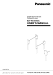
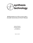
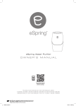
1
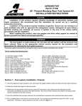
Mode
Timer
0n/ 0ff
0F
Fan Only Cool
Dry Money Saver ®
hr
Auto
Swing
Fan
Speed
Power
Temp
CP10
CP12
Mode
Timer
0n/ 0ff
0F
Fan Only Cool
Dry Money Saver ®
Temp
201
7
hr
Auto
Swing
Fan
Speed
Power
Congratulations! Thank you for choosing
Friedrich.
Your Friedrich unit is designed for
maximum comfort and quietness.
Table of Contents
Introduction ..................................................................................2
Safety Precautions.......................................................................3
How to operate your Friedrich ...................................................5
Adjusting the Air Flow Direction.................................................6
Care and Maintenance .................................................................7
Hardware Location .......................................................................8
Installation Instructions..........................................................9
Troubleshooting Tips .................................................................17
Warranty ......................................................................................18
Introduction
Before Operating Your Unit
Make sure the wiring is adequate for your unit.
If you have fuses, they should be of the time delay type. Before you install or relocate this unit, be sure that
the amperage rating of the circuit breaker or time delay fuse does not exceed the amp rating listed in figure 1.
H
DO NOT use an extension cord.
The cord provided will carry the proper amount of electrical power to the unit; an extension cord will not.
This insures proper grounding. If you have a two-prong receptacle you will need to have the circuit replaced
by a certified electrician with a grounded circuit that meets all national and local codes and ordinances. You
must use the three-prong plug furnished with the air conditioner.
115V~
15
230V~
125
NEMA NO.
5-15P
Figure 1
Power cord may include a current
interrupter device. A test and reset button is
provided on the plug case. The device
should be tested on a periodic basis by first
pressing the TEST button and then the
RESET button. If the TEST button does not
trip or if the RESET button will not stay
engaged, discontinue use of the air
conditioner and contact a qualified service
technician.
N OT E !
Aluminum house wiring may pose special problems. Consult a qualified electrician.
For the Best Cooling Performance and Energy Efficiency
Keep the filter clean
Make sure that your air conditioner is always in top performing condition by cleaning the filter regularly.
Instructions for removing and cleaning the filter can be found on page 7.
Provide good air flow
Make sure that the airflow to and from the unit is clear. Your air conditioner puts the air out at the side of
the unit, and takes in air at the left. Airflow is critical for good operation. It is just as important on the
outside of the building that the airflow around the unit exterior is not blocked.
Unit Placement
If your air conditioner can be placed in a window or a wall that is shaded by a tree or another building, the
unit will operate even more efficiently. Using drapes or blinds on the sunny side of the dwelling will also
add to your unit's efficiency.
Insulation
Good insulation will be a big help in maintaining desirable comfort levels. Doors should have weather
stripping. Be sure to caulk around doors and windows.
2
E
CP12
PLUG FACE
N
CP10
G
MODEL
CIRCUIT RATING OR
TIME DELAY FUSE
AMP
VOLT
S I L
Make sure that the receptacle is compatible with the wall plug provided.
Safety Precautions
To prevent injury and property damage, follow these instructions.
■Incorrect operation due to ignoring instructions can cause harm or damage. The seriousness is classified
by the following indications.
WARNING
This symbol indicates the possibility of death or serious injury.
CAUTION
This symbol indicates the possibility of injury or damage to
properties only.
■Meanings of symbols used in this manual are as shown below.
Never Do This
Always Do This
WARNING
Plug in the power plug
properly.
Do not operate or stop the
unit by inserting or pulling
out the power plug.
Do not damage or use an
unspecified power cord.
• Otherwise, it will cause electric
shock or fire due to heat
generation.
• It will cause electric shock or fire
due to heat generation.
• It will cause electric shock or fire.
• If the power cord is damaged, it must
be replaced by the manufacturer or a
Friedrich-certified service agent.
Do not modify power cord
length.
Do not operate with wet
hands or in damp
environment.
Do not direct air flow directly
at room occupants.
• It will cause electric shock or fire
due to heat generation.
• It will cause electric shock.
• This could lead to health problems.
3
3
7
5
A ir
P urifier
Mode
Timer
0n/ 0ff
0F
Fan Only Cool
1
Temp
2
hr
Dry Money Saver ®
Fan S peed
Auto
Swing
Fan
Speed
4
Power
5
Temp
4
Power
2
6
dry operation.
(dehumidify operation)
6
1
T imer
Auto
Swing
Mode
A
S wing
3
6. AUTO SWING
This button can automatically control the air flow
direction.
7
To receive the signal from remote controller.
Care and Maintenance
Turn the power off and unplug the power plug before cleaning the air conditioner.
Air Filter
The air filter behind the inlet grille should be checked and cleaned at least once every 2 weeks (or as
necessary) to maintain optimal performance of the air conditioner.
How to remove the air filter
1. Open the inlet grille upward by pulling out the bottom of the inlet grille.(a)
2. Remove the air filter from the front grille assembly by pulling the air filter up slightly.
3. Wash the filter using lukewarm water below 104°F(40°C).(b)
4. Gently shake the excess water from the filter. When completely dry, replace the filter.
b
Drainage
The base pan may overflow due to high humidity. To drain
the excess water, remove the drain cap from the back of
the unit and secure the drainpipe. However, excess water may
drip out of the back of the basepan, which is normal operation.
When pressing the drainpipe into place, apply force in the
direction away from the fins to avoid injuring yourself.
Drain pipe
Drain cap
7
Hardware Location
Product Features
Vertical Air Deflector
(Horizontal Louver)
Horizontal Air Deflector
(Vertical Louver)
Air Discharge
0F
hr
l
®
Coo
aver
Only
ey S
Fan
Mon
Dry
Auto
g
Swin
e
Pow
r
p
Tem
T
rem
iT
aF
pme
r ew
ed o
M
dee
pS n
oP
r
r e i f ii A
ru P
Fand
e
Spe
Front Grill
Auto
Swing
Air Intake(Inlet Grille)
Air Filter
Remote Controller
Cabinet
Brace
SUSPENSORES
Condenser
CONDENSADOR
Mod
an Only
e
Coo
Dry
l
Tim
0n/ 0er
ff
0F
Mon
ey Save
Fan
Spe
ed
r®
hr
Temp
Auto
Swin
g
Base
BANDEJA
Pan
Compressor
COMPRESOR
Pow
er
Power
Cord ELÉCTRICA
CABLE
DE CONEXIÓN
Control Board
DE CONTROL
PANEL
Evaporator
EVAPORADOR
8
ENGLISH
CAUTION
This appliance should be installed in accordance with local and national wiring regulations. This
manual acts as a guide to help to explain product features.
Installation Instructions
Read these instructions completely and carefully.
Tools You Will Need
❒ Phillips-head screwdriver
❒ Flat-blade screwdriver
❒ Ruler or tape measure
❒ Scissors or knife
❒ Pencil
❒ Level
❒ Hammer
Before You Begin
NOTE TO INSTALLER: Leave these
instructions with the air conditioner after
installation is complete.
CAUTION:
Do not under any circumstances, cut or remove
the third (ground) prong from the power cord.
Do not change the plug on the power cord of
this air conditioner.
NOTE TO CONSUMER: Keep this Installation
and Operation Manual for future use.
Aluminum house wiring may present special
problems ; consult a qualified electrician.
Important notes:
It is recommended that proper attire be worn
during installation.
For personal safety, this air conditioner must
be properly grounded.
It is important to have the wall outlet and circuit
checked by a qualified electrician if there is any
doubt as to whether a proper ground exists.
9
How to Install the Unit
Fence
Awning
2. Install the unit where the sunlight does not
shine directly on the unit.
Cooled air
30"~60"
3. The outside of the cabinet must extend outward
for at least 12" and there shouldbe no obstacles,
such as a fence or wall,within 20" from the back
of the cabinet, as it will prevent heat radiation
of the condenser.
Restriction of outside air will greatly reduce
the cooling efficiency of the air conditioner.
Heat
radiation
About 1/2"
Over 20"
CAUTION: DO NOT cover or block any of the side louvers. All side louvers of the cabinet must remain
exposed and unobstructed to the outside of the structure.
4. Install the unit with a rear, downward slope, so the back is slightly lower than the front
(about 1/4" bubble on a level). This will force condensation to flow to the outside.
5. Install the unit with the bottom about 30"- 60" above the floor level.
Window Requirements
NOTE: All supporting parts should be secured to firm wood, masonry, or metal.
• This unit is designed for installation in standard
double hung windows with actual opening widths
from 27" to 39".
• The top and bottom window sash must open
sufficiently to allow a clear vertical opening of 16"
from the bottom of the upper sash to the window
stool.
27" to 39"
16" min
(With frame curtain)
Stool
Offset
1
/2" to 11/4"
Sill
Interior wall
23 5/8" min.
(Without frame curtain)
10
Exterior
ENGLISH
1. To prevent vibration and excess noise,
make sure the unit is installed securely
and firmly
Installation Kit Contents
Type B:3EA
(SCREW)
10mm
Type D:2EA
(NUT)
4
Type C:5EA
(SCREW)
2
16mm
1
Type E:2EA
(FRAME CURTAIN) 5
3
16mm
Type A:13EA
(SCREW)
Type F:2EA
(SILL SUPPORT)
6
Type G:2EA
(BOLT)
7
10
Type H:1EA
(FOAM-STRIP)
8
Type K:2EA
(FRAME-GUIDE)
9
10
Type L:1EA
(WINDOWLOCKINGBRACKET)
Type N:1EA
12
(DRAIN JOINT PIPE)
Have the following tools available for installation:
* Screwdriver (Slotted and Phillips)
* Knife
* Pencil
* Ruler
* Hammer
* Level
11
Type M:1EA
(FOAM-PE)
11
Suggested Tool Requirements
SCREWDRIVER(+, -), RULER, KNIFE, HAMMER, PENCIL, LEVEL
2. Slide the unit out from the cabinet by gripping
the base pan handle and pulling forward while
bracing the cabinet. (Fig.2)
Mode
an Only
Cool
Dry
Timer
0n/ 0
ff
0
F
hr
Money
Saver
0F
®
hr
Fan
Speed
Auto
Swing
Temp
Power
Fig. 1
3. Cut the window sash seal to the proper length.
Peel off the backing and attach the Foam-PE to
the underside of the window sash. (Fig.3)
4. Insert the Frame guides into the bottom of the
cabinet. (Fig.4)
Mode
an Only
Cool
Dry
Timer
0n/ 0
ff
0
F
hr
Money
Saver
®
Fan
Speed
Temp
0F
hr
Auto
Swing
Power
Fig. 2
5. Insert the Frame Curtain into the Upper Guide
and Frame Guides.(Fig.4)
6. Fasten the curtains to the unit with 8 Type
A screws. (Fig.4)
Foam-PE
Fig. 3
Upper guide
Screw
(Type A)
1
Screw(Type A)
Frame guide
12
1
9
Fig. 4
ENGLISH
Shipping screws
PREPARATION OF CHASSIS
1. Remove the screws which fasten the cabinet
at both sides and at the back. (Fig.1)
Cabinet Installation
1. Open the window. Mark a line on center of the
window stool.Carefully place the cabinet on the
window stool and align the center mark on the
bottom front with the center line marked in the
window stool. (Fig. 1)
Upper Guide
Window stool
Front Angle
2. Pull the bottom window sash down behind the
Upper Guide until they meet. (Fig. 2)
NOTE: Do not pull the window sash down so
tightly that the movement of Frame
Curtain 5 is restricted.
Window Sash
Fig. 1
Upper guide
Foam-PE 11
Cabinet
Frame Curtain 5
Foam-PE
Fig. 2
3. Loosely assemble the Sill Support 6 using
the parts . (Fig. 3)
I NDO O R
O UT DO O R
Sill Support
Bolt
4. Select the position that will place the Sill
Support 6 near the outer most point on sill.
(Fig. 4)
Nut
7
9
Screw(Type A)
Fig. 3
1
About 1/2"
Frame Guide
4
NOTE: Be careful when you install the cabinet
(Frame Guides 9 are broken easily).
5. Attach the Sill Support 6 to the cabinet track
hole in relation to the selected position using
2 -type A screws in each support.
( Fig. 4).
13
6
Cabinet
I NDO O R
OUTDOOR
Fig. 4
6. The cabinet should be installed with a very slight
tilt (about 1/2") downward toward the outside
(See Fig. 5). Adjust the bolt and the nut of
Sill Support 6 for balancing the cabinet.
Sill Support 6
7. Attach the cabinet to the window stool by driving
the screws 2 [Type B: Length 16mm (5/8 inch)
and below.] through the front angle into window
stool. (Fig. 5)
Sash track
8. Pull each Frame Curtain 5 to each window
sash track, and repeat step 2. (Fig. 5)
Front Angle
Screw(Type B) 2
Sill Support 6
Fig. 5
9. Attach each Frame Curtain 5 to the window
sash using screws 3 (Type C). ( Fig. 6)
CAUTION: Do not drill a hole in the bottom pan.
The unit is designed to operate with
approximately 1/2" of water in bottom
of pan.
There is no need to add water if the
pan is dry.
Type C 3
Fig. 6
10. Slide the unit into the cabinet. ( Fig. 7)
CAUTION: For security purposes, reinstall the 2
screws (Type A) at cabinet's side, that
were removed in step 1 on page 12.
Mode
an Only
Cool
Dry
0F
Saver
®
Temp
Screw(Type A)
Power cord
Timer
0n/ 0ff
Money
Fan
Speed
hr
Auto
Swing
Power
1
Screw(Type A)
1
Fig. 7
11. Cut the Foam-Strip 8 to the proper length
(window width) and wedge between the upper
window sash and the lower window sash.
( Fig. 8)
Foam-Strip 8
Fig. 8
14
ENGLISH
About 1/2"
Screw(Type B) 2
12. Attach the Window Locking Bracket
screw 3 . ( Fig. 9)
10
with a Type C
Window locking
bracket 10
Fig. 9
13. Attach the front grille to the cabinet by inserting the
tabs on the grille into the tabs on the front of the
cabinet. Push the grille in until it snaps into place.
(Fig. 10)
Fig. 10
14. Pull down the inlet grille and secure it with a Type A
screw 1 through the front grille. ( Fig. 11)
0F
hr
15. Window installation of room air conditioner is now
completed. See ELECTRICAL DATA for
plugging the power cord into the properly
rated electrical outlet.
15
Dry
Fan
Speed
Money
Saver
®
Auto
Swing
Power
Temp
Fig. 11
Through-the-Wall Installation Instructions-Optional
The case may be installed through-the-wall
in both existing and new construction.
1 IMPORTANT (cont.)
D Secure with 14 wood screws anchored at
Read completely, then follow step-by-step.
NOTE: Obtain all materials locally for
mounting the air conditioner through the-wall.
Ieast an inch into the wall support structure.
NOTE: Drill pilot holes, if necessary, for
proper installation. If the frame is oversized,
use shims to prevent case distortion.
H
2 FINISH THE WALL OPENING
A Caulk all four sides on the outdoor side of
Through-the-wall installation is not
appropriate if any of the side or top louvers
in the case will be obstructed by the wall.
All side and top louvers in the case must
project on the outdoor side of the wall.
N
The room side of the case must project
into the room far enough to maximize the
balance of the unit.
G
the case to prevent moisture from getting
through to the interior wall. Use of flashing
(drip rail) will further prevent water from
dripping inside the wall and down the
outsida of the building.
S I L
1 IMPORTANT
E
The case must be installed level from sideto side and with a slight tilt from front to
rear. Use a level; no more than a 1/2 bubble
will be the correct case slant to the outside.
Lintel angle is required to support bricks or
blocks above opening.
Flashing is required and should extend the
length of the opening to ensure no inside
cavity leakage occurs.
A Remove the air conditioner from the case.
For specific instruction, refer to the Window
Installation Instructions.
B Make certain that a wall receptacle is
available close to the hole location or make
arrangementsto install a receptacle.
B Place the air conditioner into the case.
For specific instruction, refer to the Window
Installation Instructions.
C Place the case in the wall opening and
place wood support strips between the case
bottom and the flashing on both sides of the
bottom rail. They should be the same height
as the bottom rail and the same length as
the wall opening.
16
Troubleshooting Tips
Troubleshooting Tips save time and money! Review the chart below first and you may not need to call for service.
Normal Operation
• You may hear a pinging noise caused by water being picked up and thrown against the condenser
on rainy days or when the humidity is high. This design feature helps remove moisture and improve
efficiency.
• You may hear the thermostat click when the compressor cycles on and off.
• Water will collect in the base pan during high humidity or on rainy days. The water may overflow and
drip from the outdoor side of the unit.
• The fan may run even when the compressor does not.
• Your air conditioner is designed to cool in warm weather when the outside temperature is above
60°F(16°C) and below 115°F(46°C).
Abnormal Operation
Problem
Air conditioner
does not start
Air conditioner
does not cool as it
should
Air conditioner
freezing up
Possible Causes
What To Do
■ The air conditioner is
unplugged.
• Make sure the air conditioner plug is pushed
completely into the outlet.
■ The fuse is blown/circuit
breaker is tripped.
• Check the house fuse/circuit breaker box and
replace the fuse or reset the breaker.
■ Power failure.
• If power failure occurs, turn the mode control to Off.
When power is restored, wait 3 minutes to restart the
air conditioner to prevent tripping of the compressor
overload.
■ The current interrupter
device was tripped on
the power cord.
• Press the RESET button located on the power
cord plug. If the RESET button will not stay eng
aged, discontinue use of the air conditioner and
contact a qualified service technician.
■ Airflow is restricted.
• Make sure there are no curtains, blinds, or furniture
blocking the front of the air conditioner.
■ The THERMOSTAT may
not be set high enough.
• Push temperature setting button to coolest
temperature setting of 60°F.
■ The air filter is dirty.
• Clean the filter at least every 2 weeks.
See the operating instructions section.
■ The room may have been
hot.
• When the air conditioner is first turned on you need
to allow time for the room to cool down.
■ Cold air is escaping.
• Check for open furnace floor registers and cold air
returns.
• Set the air conditioner's vent to the closed position.
■ Cooling coils have iced up.
• See Air Conditioner Freezing Up below.
■ Ice blocks the air flow and
stops the air conditioner
from cooling the room.
• Set the mode control on high fan until the ice thaws
out. This may indicate a bigger problem.
17
ENGLISH
FRIEDRICH AIR CONDITIONING CO.
Post Office Box 1540 • San Antonio, Texas 78295-1540
(210) 357-4400 • FAX (210) 357-4490
ROOM AIR CONDITIONERS
LIMITED WARRANTY
FIRST YEAR
ANY PART: If any part supplied by FRIEDRICH fails because of a defect in workmanship or material within twelve months from date of
original purchase, FRIEDRICH will repair the product at no charge, provided room air conditioner is reasonably accessible for service.
Any additional labor cost for removing inaccessible units and/or charges for mileage related to travel by a Service Agency that exceeds
25 miles one way will be the responsibility of the owner. This remedy is expressly agreed to be the exclusive remedy within twelve
months from the date of the original purchase.
SECOND THROUGH FIFTH YEAR
SEALED REFRIGERANT SYSTEM: If the sealed refrigeration system (defined for this purpose as the compressor, condenser coil,
evaporator coil, reversing valve, check valve, capillary, filter drier, and all interconnecting tubing) supplied by FRIEDRICH in your Room
Air Conditioner fails because of a defect in workmanship or material within sixty months from date of purchase, FRIEDRICH will pay a
labor allowance and parts necessary to repair the Sealed Refrigeration System; PROVIDED FRIEDRICH will not pay the cost of diagnosis
of the problem, removal, freight charges and transportation of the air conditioner to and from the Service Agency, and the reinstallation
charges associated with repair of the Sealed Refrigeration System. All such cost will be the sole responsibility of the owner. This remedy
is expressly agreed to be the exclusive remedy within sixty months from the date of the original purchase.
APPLICABILITY AND LIMITATIONS: This warranty is applicable only to units retained within the Fifty States of the U.S.A., District of
Columbia, and Canada. This warranty is not applicable to:
1. Air filters or fuses.
2. Products on which the model and serial numbers have been removed.
3. Products which have defects or damage which results from improper installation, wiring, electrical current characteristics, or
maintenance; or caused by accident, misuse or abuse, fire, flood, alterations and/or misapplication of the product and/or units
installed in a corrosive atmosphere, default or delay in performance caused by war, government restrictions or restraints, strikes,
material shortages beyond the control of FRIEDRICH, or acts of God.
OBTAINING WARRANTY PERFORMANCE: Service will be provided by the FRIEDRICH Authorized Dealer or Service Organization
in your area. They are listed in the Yellow Pages.If assistance is required in obtaining warranty performance, write to: Room Air Conditioner
Service Manager, Friedrich Air Conditioning Co., P.O. Box 1540, San Antonio, TX 78295-1540.
LIMITATIONS: THIS WARRANTY IS GIVEN IN LIEU OF ALL OTHER WARRANTIES. Anything in the warranty notwithstanding,
ANY IMPLIED WARRANTIES OF FITNESS FOR PARTICULAR PURPOSE AND/OR MERCHANTABILITY SHALL BE LIMITED TO
THE DURATION OF THIS EXPRESS WARRANTY. MANUFACTURER EXPRESSLY DISCLAIMS AND EXCLUDES ANY LIABILITY
FOR CONSEQUENTIAL OR INCIDENTAL DAMAGE FOR BREACH OF ANY EXPRESSED OR IMPLIED WARRANTY.
NOTE: Some states do not allow limitations on how long an implied warranty lasts,or do not allow the limitation or exclusion of consequential
or incidental damages,so the foregoing exclusions and limitations may not apply to you.
OTHER: This warranty gives you specific legal rights, and you may also have other rights which vary from state to state.
PROOF OF PURCHASE: Owner must provide proof of purchase in order to receive any warranty related services.
All service calls for explaining the operation of this product will be the sole responsibility of the consumer.
All warranty service must be provided by an Authorized FRIEDRICH Service Agency, unless authorized by FRIEDRICH prior to
repairs being made.
In case of questions regarding the provisions of this warranty, the English version will govern.
Revised 11/07
18