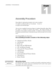
1
MOTM-830 Dual-Mode Mixer
Assembly Instructions & Owner’s Manual
Synthesis Technology
6625 Quail Ridge Dr.
Fort Worth, TX 76180
(817) 498-3782
www.synthtech.com
May 30, 2001
MOTM-830 PARTS LIST
Please carefully check that all parts are in your kit. If you have a suspected shortage, please
call or email. If you get free extra stuff, keep it for next time.
Capacitor bag, containing the following 10 parts:
2ea 10mfd, 50V Electrolytic
4ea 22pf (marked 220) ceramic axial
4ea 0.1mfd (marked 104) ceramic axial
C9, C10
C1, C6, C7. C8
C2, C3, C4, C5
Resistor bag, containing the following 24 parts:
13ea 100K 1% (brown, black, black, orange)
3ea 10K (brown, black, orange)
2ea 1K (brown, black, red)
2ea 44K2 1% (yellow, yellow, red, red)
2ea 49K9 1% (yellow, white, white, red)
1ea 150K 1% (brown, green, black, orange)
1ea 51K (green, brown, orange)
R6, R9-13, R18-24
R5, R7, R16
R4, R14
R8, R17
R1, R3
R2
R15
IC bag, containing the following 3 parts:
2ea OP285GP precision dual opamp
1ea TL072 dual op amp
U1, U2
U3
Misc #1 bag, containing the following 4 parts:
2ea Axial ferrite beads (plain, gray things)L1, L2
1ea MTA-156 power connector
JP1
1ea SPDT (ON-ON) toggle switch M2012
SW1
Knobs, 7ea, ALCO PKES90B1/4
Jacks, containing
7ea Switchcraft 112A
1ea Switchcraft 114B (contains switch SW2)
SYNTHESIS TECHNOLOGY
MOTM-830 ASSEMBLY 5/30/01
WWW.SYNTHTECH.COM
PAGE 2
Pots, 7ea containing the following:
3ea 100K linear conductive plastic (Bourns)
1ea 100K linear cermet (Spectrol 149)
3ea 100K log conductive plastic (Spectrol 148)
VR5, VR6, VR7
VR4
VR1, VR2, VR3
Front panel
Mounting bracket
Wire bag, containing the following 14 wires:
6ea RG-174 coax, 4 ½ inches
2ea RG-174 coax, 7 inches
4ea 3-wire set, 22ga. 6 inches (orange/white/gray)
1ea 2-wire set, 22ga. 3 inches (red/black)
1ea Power Cable, 20”
Hardware bag, containing:
4ea #8-32 x 3/8 black screws (for mounting module to rack)
4ea #6-32 x 1/2 zinc screws (for attaching pc board to bracket)
4ea 1/4 inch aluminum spacers
6ea #6 KEPS nuts (2 for attaching bracket to front panel, 4 for pc board)
3ea small heat-shrink tubing
9ea small tie-wraps
Organic Solder
No-clean Solder
PC Board, MOTM-830
SYNTHESIS TECHNOLOGY
MOTM-830 ASSEMBLY 5/30/01
WWW.SYNTHTECH.COM
PAGE 3
GENERAL INFORMATION
Thank you for purchasing the MOTM-830 Dual Mode Mixer. If you have any issues concerning
the building or use of the kit, please contact us at (817) 498-3782 or by email:
[email protected].
This kit should take the average builder between 2 and 3 hours. The kit contains many
different resistors and special parts. However, please remember this is NOT a speed contest; it
is an accuracy contest. There is no rule that you have to complete the entire kit in one day (as
long as you wash the flux off!).
Successful kit building relies on having the proper tools. Here is a list of what you will need to
build your MOTM-830:
•
•
•
•
•
•
•
•
•
•
•
Soldering iron, 50W max power
Needle-nose or chain-nose pliers
Diagonal cutters
Allen key set for securing the knobs (1/16” or 1.6mm)
Magnifying glass: to read the capacitor codes and to inspect solder joints
Lead bending tool (optional, but makes the job go much faster)
DVM (Digital Volt Meter) or oscilloscope (to check the output)
#1 Philips screwdriver
Fingernail brush for washing off the organic flux
Old towel for blotting dry pc board
Heat-shrink gun is highly recommended!
For more information of tools used and suggestions, see the MOTM FAQ and Tutorial pages at
http://www.synthtech.com.
HOW TO FOLLOW THE DIRECTIONS
Please read the entire instruction before proceeding. There may be valuable information at the
next to it. After you complete the
end of the instruction. Each instruction has a check box
instruction, check the box. This way you can keep track of where you are in the process.
VERIFY THE PARTS LIST
Verify that all of the parts are in the kit as shown on the parts list.
SYNTHESIS TECHNOLOGY
MOTM-830 ASSEMBLY 5/30/01
WWW.SYNTHTECH.COM
PAGE 4
A WORD ON SOLDERING
There are 2 very different types of solder used in the kit. Most of the soldering uses ‘Organic
Flux’ solder. This is strictly for use on the pc board, and is NOT to be used on the front
panel wiring!
In order for solder to ‘stick’ to the copper, a chemical called ‘flux’ is embedded in the solder. The
flux leaves a residue on the pc board that should be cleaned with warm water. DO NOT USE
SOAP OR OTHER CLEANSERS. Most of the parts in the kits are ‘waterproof’ and can be
washed in the sink. The flux is OSHA approved for flushing down the drain, so don’t worry
about that! A soft brush is used to gently scrub the board. We recommend a ‘fingernail brush’,
which is about 1” x 2” and can be found for about $1.
The other type of solder is called ‘No Clean Flux’; because as the name implies it does not
require washing. This solder is used for wiring the pots, switches, jacks, etc. This solder is
harder to use on the pc board; because even when melted, it is not very fluid (about the
consistency of toothpaste). We will use it VERY SPARINGLY on the pc board.
OK, let’s get started on the board!
PART #1: SOLDERING THE RESISTORS
Since there are more resistors than anything else, we will start here. If you do not know the
resistor color code, refer to the parts list. Resistors are not polarity sensitive, but the board will
be easier to debug (and look nicer) if you point the first color band in the same direction for all
the parts. The color code is also in the README FIRST document that every customer receives
with his or her first order.
You will start by soldering in ALL of the resistors.
Find the RESISTOR bag.
Find the MOTM-830 blank pc board. There is a copy (larger than actual size) of the
silkscreen which shows where the parts go at the end of this document. It will be useful
if you locate the part on the print first, put the part in the board, then ‘check off’ the
silkscreen. All parts are inserted from the side of the board with the white silkscreen
(the “top” side).
NOTE: some reference designators are under the resistor! Be careful.
We will stuff the resistors by value to make things easier. The resistors (and other longleaded parts) are inserted on a 0.4 inch spacing. The important thing is to be sure that
the part is sitting all the way down on the board. Push the leads in the holes, push the
part on the board, and then bend the leads on the bottom outwards to a 45 degree angle
(roughly!). This is called ‘cinching the leads’: and keeps the part from falling out! From
the bottom of the board, solder (using the organic flux), applying heat to the pad for
about a half second first, then applying just enough solder to make a small puddle that
SYNTHESIS TECHNOLOGY
MOTM-830 ASSEMBLY 5/30/01
WWW.SYNTHTECH.COM
PAGE 5
looks like a tiny pyramid. Enough solder should flow in the hole such that on the top
(component) side, a small amount is on the top pad as well
The rule of soldering: don’t use too much, you can always add more! Cut the leads flush
with the top of the solder joint with your diagonal cutters.
NOTE: later in the assembly, you will need 6 scraps of resistor lead. Be sure to
save some!
Locate the 100K 1% resistors (13pcs). Solder the resistors into R6 (left of U1), R9, R10,
R11 (by VR3), R12 and R13 (left of U2), R18 (below C1), R19, R20, R21, R22 (by U3) and
R23 & R24 (below C2).
Locate the 10K resistors (3) and solder into R5 (by VR2), R7 (by R6) and R16 (below
R18).
Locate the 1K resistors (2) and solder into R4 (by J8) and R14 (below C6).
Locate the 44K2 1% resistors (2) and solder into R8 (below C8) and R17 (by VR3).
Locate the 49K9 1% resistors (2) and solder into R1 and R3 (left of VR2).
Locate the 150K 1% resistor and solder into R2 (by VR2).
Locate the 51K resistor and solder into R15 (by C5). This completes the resistors.
PART #2: BOARD WASH #1
Verify all the resistors are in the correct position.
Verify all the resistors are flat on the board. Correct if needed. Check solder joints.
Wash the board in warm water, gently scrubbing both sides. DO NOT USE ANY SOAP!
Just water! Blot dry with old towel and let it sit for at least 15 minutes.
Take a little break! You are about 1/3rd of the way finished.
PART #3: CAPACITORS
Locate the CAPACITOR bag.
SYNTHESIS TECHNOLOGY
MOTM-830 ASSEMBLY 5/30/01
WWW.SYNTHTECH.COM
PAGE 6
Locate the 22pf ceramic axial caps (4) and solder into C1 (by VR2), C6 (above R14), C7
(by VR3), and C8 (above R8). DO NOT GET THESE MIXED UP WITH THE OTHER
CERAMIC CAPS OR THE MIXER WILL NOT OPERATE PROPERLY!!!
Locate the 0.1mfd axial ceramic caps (4) and solder into C2, C3, C4 and C5.
Locate the 10µfd electrolytics (2). Note that there is a stripe on the NEGATIVE
terminal. The pc board has a + on the POSITIVE terminal. Carefully stick the
capacitors into C9 and C10 with the stripe away from the + pad on the board.
PART #4: MISC and IC STUFF
Almost done with the parts on the pc board! This will finish up the soldering with the organic
flux.
Locate the MISC #1 bag and the IC bag.
Locate the ferrite beads (2). They are axial parts, gray colored with no markings. These
are non-polar, and are soldered into L1 and L2 (by JP1).
Locate the MTA-156 power connector. Solder into JP1. Note that the connector has
a ‘locking tab’ on one side. This side is the “inside” facing relative to the pc board.
Note the silkscreen symbol for JP1 has a line on one side, indicating this is the side
where the locking tab goes.
Locate the OP285GP op amps (2). Solder into U1 and U2. Note that all ICs are pointing
“down” towards the bottom edge of the pc board. The IC will have a ‘notch’ or
indentation in the top by Pin #1.
Locate the TL072 op amp. Solder into U3.
Apply a small bit of solder to the via holes. These are the small pads that allow traces to
“change sides” of the pc board. DO NOT SOLDER PADS FOR THE REMAINING
COMPONENTS!! As an example, if you look at R8, you will see 4 via holes around it.
PART #5: FINAL BOARD WASH & INSPECTION
Verify all the parts are in the correct locations. Make sure all of the ICs are pointing the
same direction.
Inspect the solder joints. Any solder shorts? Too much solder? Missing joints?
Wash the board under warm water. Scrub gently. Dry.
SYNTHESIS TECHNOLOGY
MOTM-830 ASSEMBLY 5/30/01
WWW.SYNTHTECH.COM
PAGE 7
THIS IS A GOOD STOPPING PLACE TO REST OR PUT THE KIT AWAY UNTIL
LATER. Don’t lose the trim pot, it goes on with no-clean solder in the next section.
You are now finished with the Organic flux solder. All soldering past this point is
using the No-Clean solder. You do not have to wash the board anymore.
PART #6: FINISHING THE PCB
You will now solder in the remaining parts on the pcb in preparation for wiring to the front
panel. USE THE NO-CLEAN SOLDER. BE CAREFUL!
Locate the Spectrol pots. They mount into VR1-VR4. Be sure they are flat and sticking
out perpendicular to the pc board. VR4 is different! It has ‘149’ marked on the top.
VR1-VR3 are marked ‘148’.
Locate the 8 pieces of RG-174 black coax cable. Again, note that one end has
longer wires stripped than the other. The short ends will go in the pc board in
locations J5 – J8. Look at the pc board. Notice that in the coax positions, there is a large
hole pad (lower pad) and a smaller pad (top hole). The braided wire is soldered into the
larger hole. The smaller, inner conductor goes in the top hole. BE SURE THE
SHORTER BRAIDED END GOES INTO THE PC BOARD.
The 2 LONG coax cables solder into J1 and J5. The 6 SHORT coax cables go into
the other locations. Solder each coax cable into the holes. Attach a tie-wrap to secure the
coax cable flush to the board. The tie-wrap goes down, into the left hole and up through
the right hole. Secure and trim off any excess.
Find the 4 white/orange/gray twisted wires. They go into VR5, VR6, VR7 and SW1.
Solder the White wire into pad #1, the Grey wire to pad #2 and the Orange wire into
pad #3. Solder the short stripped end into the pcb.
Find the red/black twisted wires. It solders into SW2. The Red wire goes in pad #1 and
the Black wire into pad #2.
YOU ARE NOW FINISHED WITH THE PC BOARD WORK! BREAK TIME.
PART #7: FRONT PANEL PREPARATION
You will now attach components to the front panel. It is HIGHLY recommended that you use a
set of hollow shaft nut drivers, NOT PLIERS, to tighten the nuts. This prevents scratching.
NOTE: all references to part orientation is from the REAR of the panel.
Locate the 8 Switchcraft jacks. Notice that from the rear, there is a beveled corner.
This corner is ALWAYS CONNECTED TO GROUND, USUALLY WITH A
SYNTHESIS TECHNOLOGY
MOTM-830 ASSEMBLY 5/30/01
WWW.SYNTHTECH.COM
PAGE 8
BRAIDED CONDUCTOR. Each jack has a flat washer, a lockwasher, and a ½” hex nut.
Remove the nuts and washers from each jack. Place aside. Keep the lockwasher on the
jacks.
One of the jacks is different! It has 5 lugs out the back instead of 3. This jack
contains a switch (SW2), and you MUST insert it into the OUT2 hole!!!
Insert the 8 jacks/lockwashers, with the beveled corner in the upper right corner, into
the 8 holes. Place the flat washer on the jack, then the hex nut. Hold the jack with one
hand on the backside, keeping it ‘square’. Tighten the hex nut with a nut driver. NOTE:
when tight, not much of the exposed threads of the jack are exposed.
Remember those resistor lead scraps you have been saving? They solder on the IN1 – IN6
jacks. Solder the scrap in between the TOP and the BEVELED lugs. Be sure to leave
enough space on the beveled lug to attach the coax braid.
You are now ready to attach the pc board to the bracket and then wire up to the panel.
PART #8: ATTACH PC BOARD TO BRACKET/PANEL
In the HARDWARE bag, locate 4 #6-32 x 1/2 screws, 6 #6 KEPS nuts, and 4 spacers.
Locate the mounting bracket. The pc board attaches to the bracket, with the 4
screws threading from the top of the board, through the spacers, through the
bracket, and then out the bottom of the bracket. The #6 KEPS nut attaches on the
bottom of the bracket. Note the bracket has 2 long mounting flanges with a hole
in each. These attach to the 2 threaded studs sticking out of the rear of the panel.
The 4 pots each stick in its panel hole when the bracket is screwed down on the 2
threaded posts.
Attach the pc board to the bracket. The flanges will point upwards when the pc board is
sitting on the bracket. Note that the bracket holes for the pc board are
actually oblong. This is to allow adjustment for the pc board to firmly press
up against the back of the panel. As a start, set the 4 screws ALL THE WAY
TO THE LEFT of the oblong holes. Loosely tighten the 4 KEPS nuts on the
bottom.
THIS IS A VERY IMPORTANT STEP, SO PAY ATTENTION AND READ ALL OF
IT BEFORE PROCEEDING!
Note that each of the 4 pots on the pc board have 2 hex nuts and a flat washer.
Remove the first hex nut and the washer. Set aside.
What you will do now is adjust the remaining hex nuts so that when the bracket is
all the way down on the panel’s threaded studs, all the pot hex nuts touch the rear of
the panel.
SYNTHESIS TECHNOLOGY
MOTM-830 ASSEMBLY 5/30/01
WWW.SYNTHTECH.COM
PAGE 9
Screw (by hand) each hex nut on the pots so that it is all the way on (touching
the face of the pot). Now, pick up the pc board/bracket assembly and carefully
slide it over the 2 threaded studs, making sure the pots are aligned in the holes.
Use 2 #6 KEPS nuts and tighten the bracket to the panel.
Loosen the 4 KEPS nuts on the bottom of the bracket. Slide the pcb ALL THE WAY
TO THE RIGHT AS FAR AS IT WILL GO, so that the 4 pot nuts are all pressing
against the panel. By hand, put hex nuts on the outside threads of VR1 and VR4 to
keep the pc board in place. Now, tighten the 4 KEPS nuts on the bracket. The pcb
and bracket should be secure, with no gaps visible between the panel and the pot
nuts. You may need to loosen the nuts on the pots, so that they are touching
the back of the panel. Again, make sure each pot’s nut is touching the back of
the panel (no gaps!). There will be a gap from the edge of the pc board to the panel.
Remove the hex nuts on VR1 & VR4. For all of the pots, first put on the flat washer,
then the hex nut. Tighten with a ½” nut driver.
PART #9: FINISH WIRING TO THE PANEL
Please read the following instructions carefully. In order to neatly attach the many wires to the
front panel components, the wires are soldered in a specific order.
Find the SPDT toggle switch. Insert the switch into the panel hole labeled BIAS.
Tighten the outside hex nut, but DO NOT OVERTIGHTEN!! Be sure the switch is
oriented so the lever operates “up and down” and not “side-to-side”! The lockwasher goes
on the inside of the panel.
Now you will solder to the BIAS switch. The 3 pieces of heat-shrink tubing are for the
switch lug. First, untwist the wires once or twice to leave about 1 ½ inches free for each
wire. Slide a piece of tubing on each wire. The Orange wire goes to the TOP lug, the
Gray wire goes to the MIDDLE lug and the White wire goes to the BOTTOM lug. Wait 1
MINUTE before sliding the tubing over the switch lugs (which retain heat because they
are silver-plated). Use a heat shrink gun to shrink the tubing over the wire/lugs.
Now you will solder to the 8 jacks. Each jack has 3 lugs (except OUT2 which has 5) from
the rear we will refer to them as LEFT, TOP, and BEVELED. The TOP lug is for the
switched contact: this is a NC (normally closed) contact that is opened when a plug is
inserted.
Solder the coax in J8 to the OUT1 jack. The braid goes to the BEVELED lug. The inner
conductor goes to the LEFT lug. This is true of ALL coax wires.
Solder red/black wire in SW2 to the OUT2 jack. The Red wire goes to the RIGHT lug
(below the Beveled lug). The Black wire goes to the BOTTOM lug. The TOP lug is NOT
connected.
SYNTHESIS TECHNOLOGY
MOTM-830 ASSEMBLY 5/30/01
WWW.SYNTHTECH.COM
PAGE 10
Solder the coax in J4 to the OUT2 jack. Braid to beveled, inner wire to LEFT.
Solder the coax in J7 to IN3.
Solder the coax in J3 to IN6.
Solder the coax in J6 to IN2.
Solder the coax in J2 to IN5.
Solder the coax in J5 (long) to IN1.
Solder the coax in J1 (long) to IN4. Use a tie-wrap to bundle the coax together (you don’t
have to bundle ALL of them, just enough to get them out of the way).
Now we will solder to the 3 blue Bourns pots. In all cases, the Orange wire goes to the
LEFT lug, the Gray wire to the MIDDLE lug and the White wire to the RIGHT lug. The
wire sets and pots are in order: VR5 is the IN1 pot, VR6 is the IN2 pot and VR7 is the
IN3 pot. The ‘1 2 3’ silkscreen indicators match the teeny-tiny ‘ 1 2 3’ numbers stamped
above the pot lugs.
Rotate all of the front panel pots fully counter-clockwise. Locate the KNOBS.
Notice each knob has a white line on it. Place the knob on the pot shaft,
align the white line to the ‘0’ (or –5) tick mark, and tighten the hex screw. The silver
part of the knob has a protective clear plastic overlay that can be removed if
desired. Gently rub with your fingernail across it and it will peel off.
************************************************************************************
CONGRATULATIONS! YOU HAVE FINISHED BUILDING THE MOTM-830!
************************************************************************************
All that’s left to do is test it! But before we do, please read the following Theory of Operation.
THEORY OF OPERATION
Compared to most other MOTM modules, the MOTM-830 is fairly simple (well, that’s easy for
us to say!). The ‘audio’ portion of the Mixer (IN4 – IN6) consists of an inverting summer U2A
followed by an inverter (U2B). The 22pf caps C6 and C7 are used to keep high-frequency
overshoots out of the outputs. The OP285 is a special type of opamp: not only is it fast and has
low THD for audio, it also has superior DC drift and offset specifications.
The gain of each ‘channel’ is set by the ratio of the feedback resistor R17 to the input resistance
seen at the negative terminal (pin 2), which are R9-R11. The gain equation is –(R17/R11) for
SYNTHESIS TECHNOLOGY
MOTM-830 ASSEMBLY 5/30/01
WWW.SYNTHTECH.COM
PAGE 11
IN4, -(R17/R10) for IN5 and –(R17/R9) for IN6. This corresponds to a gain of –0.442 per
channel. The following inverter has gain of –1 so the total path gain per channel in the ‘audio
path’ is +0.442.
So, if you put in 10V pk-pk into IN4 and set the panel pot to ‘10’, the output on OUT A jack is
4.42V pk-pk. If you put 10V pk-pk into IN4 and IN5, turning both to ‘10’ the output would be
8.84V pk-pk.
The panel pots used on IN4 – IN6 are called ‘log’ or ‘audio taper’ pots. These pots have a nonlinear resistance versus rotation, because the human ear is non-linear in terms of perceived
loudness versus signal amplitude. In other words, making a signal twice as big (say 1V pk-pk
to 2V pk-pk) does not make the signal twice as loud. The log pots try to attenuate the signal in
such a manner that as you turn the knob, the loudness (‘volume’) changes smoothly from soft to
loud.
The ‘DC’ path of the Mixer is more ‘fancy’ than the ‘audio’ portion. IN2 and IN3 have a circuit
called a ‘reversing attenuator’ on them. This allows the panel pot to select gains of –1 to +1
before the summing amp. Signals and DC voltages can be ‘inverted’ (change of polarity). Note
that due to the fact it’s nearly impossible to set the panel pot perfectly in the middle of
rotation, you cannot expect 100% muting of inputs on IN2 and IN 3.
Like the 3 ‘audio’ channels, the channel gain is set by R8/R6 for IN1, etc. which is –0.442. U1A
is the inverter, but is has other functions. First, a DC bias (offset) can be added to the output
by SW1 and VR4. The amount of bias is set by R1/R2 or 1/3 of +15/-15, which is +5 to –5V of
bias.
Second, the ‘audio’ channels can be added in by SW2 and R18. If SW2 is closed, the 3 ‘audio’
channels are added in as a group with a gain of R1/R18 or 0.5
SW2 is built into J4, which is a stereo jack. But, being the clever designers that we are, will use
a ‘trick’. The trick is that when a mono patch cord is inserted, the ‘ring’ connection of the jack is
shorted to ground by the plug. We depend on this to short R18 to ground when the plug is
inserted. Why is this a big deal? Because if R18 is ‘floating’, it acts like an antenna! It picks up
all sorts of buzz, noise and even radio stations! So, we purposely use a stereo jack and a mono
plug.
So, if NO PATCHCORD is plugged into OUT2, all 6 inputs are summed as above and are
present on OUT1. If you insert a plug into OUT2, the switch SW2 OPENS and the Mixer ‘splits’
into 2 parts. IN1-IN3 appear on OUT1, and IN4-IN6 appear on OUT2.
This is explained further in the USE OF THE MOTM-830 section.
TROUBLESHOOTING
If your MOTM-830 does not work, please verify ALL of the following before contacting us. The
following reference directions assume that you are looking at the pc board with the panel to the
right and the power connector to the left.
All of the ICs are pointing the same way and all notches are ‘down’.
SYNTHESIS TECHNOLOGY
MOTM-830 ASSEMBLY 5/30/01
WWW.SYNTHTECH.COM
PAGE 12
The braided wire on the coax goes to the beveled side of the jacks. Check all of the pots
and switch wiring. Check the wiring color codes on the pcb versus the instructions.
The parts are in the right places, and the panel pots/switch are wired correctly.
No solder shorts or missing joints.
USING THE MOTM-830
The main use of the ‘830 is to add audio signals, control voltages or both to form a single
output. The most common use is to add the outputs from multiple VCOs together before
feeding a filter or other processor.
The MOTM-830 is NOT INTENDED to replace a standard audio mixer in your studio. Rather,
it is a simple module without ‘coloration’ or EQ, that adds stuff up.
The unique feature of the ‘830 is that it can be ‘split’ into 2 separate mixers by inserting a
mono plug into the OUT 2 jack. This engages a switch which splits the mixer into the OUT1
group (IN1 IN2 IN 3 all added together) and the OUT2 group (IN4 IN5 IN6 all added together).
This is like a headphone jack on a stereo, that switches the speakers off when you plug in the
headphones.
The #1 difference between the ‘830 and a studio audio mixer is that there are 2 ‘reversing
attenuators’ on IN2 and IN3. These are usually used to invert (as well as attenuate) signals
plugged into these 2 inputs. Due to the circuitry used you CANNOT mute these channels to
zero as you can on the other 4 inputs. Therefore, avoid using IN2 and IN3 if you need to ‘fade
out’ during a mix. You just can’t set those pots to 50% rotation perfectly.
The MOTM-830 is set up to attenuate only. You cannot get gain out of this module. See the
CHANNEL GAIN section for more information.
AUDIO VERSUS LINEAR POTS
Since the MOTM-830 can be used for both audio or precise control voltage application, some
design compromises were used to accommodate the inputs.
On the ‘left side’ of the mixer, IN1, IN2 and IN3 are all controlled by linear pots. If you need to
add up to 3 control voltages, use this ‘side’ of the mixer. You can also add a constant DC bias
voltage by turning BIAS to ON and adjusting the BIAS pot.
The definition of a linear pot is that at 50% angular rotation (ie straight up on the pointer) the
pot wiper is 50% of the resistance to either side. This means at 50% rotation, 50% of the input
voltage is on the wiper.
Linear pots are useful for adjusting voltages.
SYNTHESIS TECHNOLOGY
MOTM-830 ASSEMBLY 5/30/01
WWW.SYNTHTECH.COM
PAGE 13
On the other hand, the ‘audio’ side of the mixer (IN4, IN5 and IN6) uses log (called audio taper)
pots. These pots, when at 50% rotation, are about 15%/85% of resistance from wiper to lug. So,
if you put in 1V dc into a log pot and set it at 50% rotation, you DO NOT get out 0.5V as
expected for a linear pot (if you are really bored, you can figure out what the answer is).
So what good are these log pots? The answer is: they are for attenuating audio signals. The
reason is that your ear is non-linear. The log pot’s strange taper is to make you think the
volume is decreasing/increasing linearly.
The linear versus log pot tapers are just to make the “human interface” easier to deal with. In
terms of the electrical characteristics of the mixer, the summing op amps don’t know or care
what the taper is. They happily add up whatever is presented to it.
This means you can put audio or CV into ANY INPUT CHANNEL YOU WANT. Just realize
that the ‘loudness’ of the audio based on the summed output voltage.
For example, IN1 is a straight input on a linear pot. IN4 is a straight input on a log pot. If you
put the same audio signal into both, and set both for ‘equal loudness’ the tick marks will not be
the same.
Conversely, if you are scaling a keyboard voltage to 1/5th range, the IN1 tick would be very
different from the IN4 tick mark.
CHANNEL GAINS
There were several design compromises made from selecting the channel and ‘group’ gains of
the Mixer.
IF YOU DON’T LIKE THE CHOICES THAT WERE MADE, YOU CAN CHANGE THEM
BY SWAPPING RESISTORS.
Read the following discussion closely to understand how & why the gains are set the way they
are from the factory.
The intent of the ‘830 is to mix signals within a MOTM system. This means the audio signals
are very hot compared to “standard’ audio signals. The MOTM system uses 10V peak-peak
audio signals, which is 10 times ‘hotter’ than normal. The first design decision was to set the
channel gains equal. This means IN1...IN6 all sum the same when the pots are fully
clockwise.
The individual channel gain is set by the input summing node resistor for that channel.
From the factory, this is a 100K, 1% resistor (R11 is for IN4, R10 is for IN5, etc). If you want to
INCREASE the individual channel gain, you DECREASE this resistor by the % you want. You
should use 1% resistors for their low noise and temperature drift.
The GROUP gain is set by R8 (for IN1 IN2 IN3 group) and R17 (IN4 IN5 IN6 group). This is
set at the factory for 0.442 (the keen reader will see this is the feedback resistor divided by the
input summing resistor).
SYNTHESIS TECHNOLOGY
MOTM-830 ASSEMBLY 5/30/01
WWW.SYNTHTECH.COM
PAGE 14
The value of this resistor is somewhat arbitrary, but within a range of possible values. This
resistor sets the MAXIMUM VOLTAGE OUT when all 3 inputs are at maximum (ie the pots
are cranked up to the right).
Assuming the worst case of 3 VCO outputs (in phase). That’s 10 + 10 + 10V possible out if the
group gain is 1. Rather than have the poor op amp clip and heat up, we decide that the
maximum output voltage is (30) * (0.442) or 13.26V pk-pk.
Now, you will raise your hand and point out that this exceeds the 10V pk-pk ‘standard’, and
you are correct. This “extra” voltage is called ‘headroom’ in MixerSpeak. This means in ‘real
life’ you don’t crank all 3 pots to ‘10’ to get 10V out. Rather, you will find they are set on
roughly the ‘8’ tick mark.
So, when the mixer is ‘split’ into 2 3:1 sections, the channel gains are all equal, and the group
gains are 0.442 which gives a maximum out (not counting BIAS) of 13.26V pk-pk for 3 10V pkpk input signals. WHEW!!!
The clever reader will now catapult out of his/her chair to shout “What happens in 6:1 mode?
Do you get 13.26 + 13.26V pk-pk out or a whopping 26.52V pk-pk signal?” Answer: NO! Give us
some credit.
Looking at the schematic, the value of R18 is setting the group gain of IN4 IN5 IN6 when in 6:1
mode. In other words, the ‘log taper’ group is added to the ‘linear taper’ group by R18, through
normally closed switch-jack SW2.
This gain is set by the ratio of R1 divided by R18 or ½. This means we FIRST sum IN4 IN5 IN6
together with a group gain of 0.442 THEN add HALF of that result to the other 3 channels.
So, in 6:1 mode, the IN4 IN5 IN6 levels are cut in half. This prevents massive output levels
with everything cranked to 10.
What is the maximum? Assuming 10V on every input and every pot set to maximum level, the
answer is 19.89V. This level is WAY TOO BIG to be used for anything, BUT is below the op
amp’s clipping level. So, even if you set the mixer up to do this, NO CLIPPING WILL OCCUR.
You will find that in 6:1 mode, you will get reasonable output levels with all the pots set to
mid-gain (which is again a design decision you can alter by resistor swapping).
Certainly, it would have been nice to reduce both groups by an equal amount, rather than have
the mixer with this ‘imbalance’ of gains. But the goal was a minimal path for best performance,
an the switching jack was the compromise (if you think there are lots of engineering decisions
in a simple mixer, wait until you try to design a VCO!)
BIAS should ONLY be used for control voltages. DO NOT APPLY DC BIAS TO AUDIO
POWER AMPS OR DAMAGE TO THE AMPS AND SPEAKERS MAY RESULT!!
SYNTHESIS TECHNOLOGY
MOTM-830 ASSEMBLY 5/30/01
WWW.SYNTHTECH.COM
PAGE 15
SPECIFICATIONS
MOTM-830 Dual-Mode Mixer
Input signal level (any input)
-7V to +7V
Output level
20V peak-peak before clipping
Output distortion
<0.01% at 1Khz
Output SNR
86dB min.
CONTROLS
IN1
Linear input
IN2, IN3
Reversing attenuator input (-1 to +1 gain)
IN4-IN6
Audio taper input
BIAS
Sets DC bias level between –5V and +5V
BIAS switch
Adds DC bias to OUT 1 jack
GENERAL
Power Supply
-15VDC @ 15 ma nominal
+15VDC @ 15 ma nominal
Size
2U x 5U
3.47” x 8.72”
88.1mm x 221.5mm
Depth behind panel
4.375 inches (111mm)
SYNTHESIS TECHNOLOGY
MOTM-830 ASSEMBLY 5/30/01
WWW.SYNTHTECH.COM
PAGE 16
J5
IN 1
J6
IN 2
J7
IN 3
8
4
VR6
100K LIN
8
R6
100K 1%
3
4
-15V
2
7
U3B
TL072
+15V
1
U3A
TL072
R20
100K 1%
5
6
VR5
100K LIN
100K 1%
R19
100K 1%
R21
R22
100K 1%
VR7
100K LIN
R24
J3
J2
J1
100K 1%
IN 6
IN 5
IN 4
+15V
R7
10K
5
6
8
4
BIAS
C2
0.1M
U1B
OP285GP
7
0.1M
C3
44K2 1%
R8
22PF
-15V
C8
R23
100K 1%
VR3
100K LOG
R9
100K 1%
VR2
100K LOG
R10
100K 1%
VR1
100K LOG
R11
100K 1%
+15V
VR4
100K LIN
CCW
CW
-15V
+15V
R16
10K
3
2
8
4
-15V
C5
SW SPDT
S1
C4
0.1M
U2A
OP285GP
1
0.1M
R17
44K2 1%
C7
22PF
150K 1%
R2
49K9 1%
R3
100K 1%
R18
BLACK
RED
100K 1%
R13
8
4
U2B
OP285GP
7
MTA-156
R5
10K
3
2
8
4
1
J8
OUT 1
114B
J4
6625 QUAIL RIDGE DR.
FORT WORTH, TX
76180
(888)818-MOTM
SYNTHESIS TECHNOLOGY
1K
C9
10M
OUT 2
FERRITE
L2
+15V
C10
10M
-15V
MOTM 830 - DUAL MODE MIXER
Size Document Number
B
M830.SCH
Date:
June
5, 2001 Sheet
1 of
Title
U1A
OP285GP
49K9 1%
R1
22PF
C1
R4
R14
1K
SW2 ON PCB IS FOR THESE WIRES.
R15
51K
5
6
100K 1%
R12
C6
22PF
JP1
1
2
3
4
L1
FERRITE
REV
A
1