1
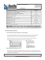
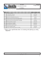
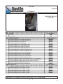
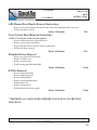
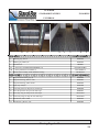
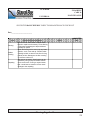
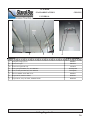
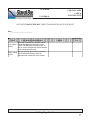
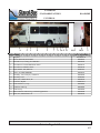
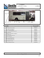
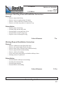
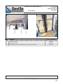
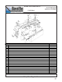
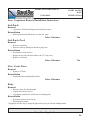
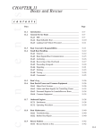
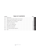
UNIVERSAL
2011
PARTS AND SERVICE MANUAL
Table of Contents
GENERAL INFORMATION
DIMENSIONS ............................................................................................................................... PAGE 4
PAINT CODES ............................................................................................................................... PAGE 4
PROD/ NUMBER .......................................................................................................................... PAGE 4
INTERIOR
SEATING TORQUE SPECS .................................................................................................. PAGE 5
DRIVER SEAT ........................................................................................................................ PAGE 6
SEAT BELTS, REAR ............................................................................................................... PAGE 6
Operating Instructions ............................................................................................................. PAGE 7
Care & Mainteance ................................................................................................................ PAGE 8
Instructions/Labor Time ................................................................................................... PAGES 9-11
DASH/CONSOLE .................................................................................................................. PAGE 12
Operating Instructions ........................................................................................................... PAGE 13
Care & Mainteance .............................................................................................................. PAGE 14
Instructions/Labor Time ......................................................................................................... PAGE 15
FRONT OVERHEAD ............................................................................................................ PAGE 16
Operating Instructions ........................................................................................................... PAGE 17
Care & Maintenance ............................................................................................................. PAGE 18
Instructions/Labor Time ........................................................................................................ PAGE 19
FLOORING ............................................................................................................................ PAGE 20
Care & Maintenance ............................................................................................................. PAGE 21
Instructions/Labor Time ........................................................................................................ PAGE 22
MODESTY PANELS/STANCHIONS .................................................................................. PAGE 23
Care & Maintenance ............................................................................................................. PAGE 24
Instructions/Labor Time ......................................................................................................... PAGE 25
CEILING ................................................................................................................................ PAGE 26
Care & Maintenance ............................................................................................................. PAGE 27
Instructions/Labor Time .................................................................................................. PAGES 28-29
WALLS .................................................................................................................................... PAGE 30
Care & Maintenance ............................................................................................................ PAGE 31
Instructions/Labor Time ......................................................................................................... PAGE 32
Table of Contents Continued
EXTERIOR
FRONT CAP & COMPONENTS ......................................................................................... PAGE 33
Care & Maintenance ............................................................................................................. PAGE 34
Instructions/Labor Times ................................................................................................ PAGES 35-36
REAR CAP & COMPONENTS ............................................................................................ PAGE 37
Care & Maintenance ............................................................................................................. PAGE 38
Instructions/Labor Times ....................................................................................................... PAGE 39
REAR BUMPER .................................................................................................................... PAGE 40
Instructions/Labor Times ..................................................................................................... PAGE 41
ROADSIDE ............................................................................................................................ PAGE 42
CURBSIDE ............................................................................................................................. PAGE 43
Care & Maintenance ............................................................................................................ PAGE 44
Instructions/Labor Times .................................................................................................. Pages 45-46
SIDE MIRRORS ................................................................................................................... PAGE 47
Instructions/Labor Times ....................................................................................................... PAGE 48
WINDOWS ............................................................................................................................. PAGE 49
Instructions/Labor Times ...................................................................................................... PAGE 50
ENTRY DOORS, MANUAL CONTROL ..................................................................... PAGES 51-54
ENTRY DOORS, MANUAL CONTROL BREAKDOWN ............................................ PAGE 55-57
GENERAL INFORMATION
DIMENSIONS
PAINT CODES
PROD/UNIT #
UNIVERSAL
GENERAL DIMENSIONS
UNIVERSAL
EXTERIOR HEIGHT, STANDARD FLOOR, without escape hatch
111"
EXTERIOR WIDTH, EXCLUDING MIRRORS
96"
EXTERIOR WIDTH, INCLUDING STANDARD MIRRORS
96"
EXTERIOR LENGTH W/BUMPER
21', 22', 24', 26'
GVWR (E350/E450 respectively)
10,700 lbs,/11,500 lbs./14,050 lbs.
INTERIOR HEIGHT
78"
INTERIOR WIDTH, FLOOR TO 24" ABOVE
92"
TURNING RADIUS 158" WB
56.7 ft. Dia.
TURNING RADIUS 176" WB
62.5 ft. Dia.
TURNING RADIUS 186" WB
65.8 ft. Dia.
WHEELBASE
138", 158", 176", 186"
* ADD 8" FOR FLAT FLOOR DESIGN
PAINT CODES
Ford Code
YZ
White
Dupont Code
B9145G Alternate #3
Unit Identification Numbers
GLAVAL BUS Production Number and Unit number
You will find these numbers at the bottom of the manufacturer Vehicle Safety Standard
Certification label. This sticker is located on the dash to the left of the steering column.
This production number does not coincide with the Vehicle Identification Numbers
(VIN) supplied by the chassis manufacturer but is specific to the bus body.
Vehicle Identification Number (VIN)
This number is the identification number for the chassis manufacturer. The VIN number is located on
the Vehicle Safety Certification Label and also stamped on a tag located in the upper right hand corner
of the dash at the windshield area.
General Information Page 1 of 1
4
SEATING
STANDARD FEATURES
SEATING
TORQUE SPECS
UNIVERSAL
SEATING
1
2
3
4
5
6
7
8
9
10
11
12
13
TORQUE SPECIFICATIONS
Driver seat to slide tracks
13 ft lbs.
Driver slide tracks to pedestal
26-33 ft lbs.
Driver pedestal to floor studs
35-45 ft lbs.
Passenger seat to baseplate, 4 nuts per seat
13 ft lbs.
Passenger seat T-leg to front bolts of baseplate (2 bolts)
15 ft lbs.
Passenger seat T-leg to rear bolts of baseplate (2 bolts)
60 ft lbs.
Passenger seat T-leg to seat track (3 bolts) 7/16-14 GR8
45-50 ft lbs.
Ford front belt anchor to stepwell
26-33 ft. lbs
Ford seat belt retractor to B-pillar
26-33 ft. lbs.
Ford seat belt D nut to wall plate
26-33 ft. lbs.
Ford adjustable latch plate to B-pillar
26-33 ft. lbs.
Seat belt to Freedman baseplate
17-21 ft lbs.
Baseplate to Perf wall angle (2 bolts) 3/8 - 16 GR8
25-30 ft lbs.
***Refer to these specifications when ever removing and replacing any seating
component.
Seating Page 1 of 7
5
SEATING
SEATING
UNIVERSAL
NEED DRIVER SEAT
COVER OPT
DRIVER SEAT
1
PART NUMBER
Driver Seat
Driver Seat Belt
OEM
OEM
PASSENGER SEATING
PART NUMBER
BF080006
BF080005
BF080013
BF080000
BF080066
B-35904
BF080010
BF080009
BF080041
BF080021
BF080007
BF080012
BF080011
BF080028
BF080028
BF080085
BF000044
BF080094
BF080027
BF080028
2
OPTG50401 FREEDMAN FW LOWBACK SGL SEAT
OPTG50403 FREEDMAN FW LOWBACK DBL SEAT
OPTG50405 FREEDMAN FW MI-HI SGL
OPTG50407 FREEDMAN FW MI-HI DBL
OPTG50406 FREEDMAN FW MID SGL RECL SEAT
OPTG50408 FREEDMAN FW MID DBL RECL SEAT
OPTG50413 FREEDMAN FW HI-BACK SGL SEAT
OPTG50415 FREEDMAN FW HI-BACK DBL SEAT
OPTG50414 FREEDMAN FW HI-BACK SGL RECL SEAT
OPTG50416 FREEDMAN FW HI-BACK DBL RECL SEAT
OPTG50000 FREEDMAN SEAT 5-PLACE LOWBACK
OPTG50001 FREEDMAN SEAT 5-PLACE MID HIGH
OPTG50002 FREEDMAN SEAT 5-PLACE HI BACK
OPTG50500 FREEDMAN MID HI (17") SGL FLIP SEAT
OPTG50501 FREEDMAN MI-HI (34") DBL FLIP SEAT
OPTG50503 FREEDMAN SGL FWD FACING FOLDAWAY - WALL MOUNT
OPTG50511 FREEDMAN DBL 34" MID-HI FF FOLDAWAY- FLOOR MOUNT
OPTG50510 FREEDMAN WHEEL WELL MOUNT FF DBL FOLDAWAY
OPTG50500 FREEDMAN MID-HI (17") SGL FLIP
OPTG50501 FREEDMAN MI-HI (34") DOUBLE FLIP
FABRIC OPTIONS
OPTG50600 FREEDMAN SEAT FABRIC - LEVEL 1
OPTG50600 FREEDMAN SEAT FABRIC - LEVEL 2
OPTG50600 FREEDMAN SEAT FABRIC - LEVEL 3
OPTG50600 FREEDMAN SEAT FABRIC - LEVEL 4
OPTG50600 FREEDMAN SEAT FABRIC - LEVEL 5
OPTG50600 FREEDMAN SEAT FABRIC - LEVEL 6
PART NUMBER
BF080002
BF080031
BF080039
BF080034
BF080018
BF080025
**REFER TO TORQUE SPECS ON PAGE 1 of 7 FOR R&R
Seating Page 2 of 7
6
SEATING
UNIVERSAL
REAR
SEAT BELTS
OPTIONAL
Seating Page 3 of 7
7
SEATING
UNIVERSAL
SEATING
OPERATING
INSTRUCTION
Seat Belt
Driver
• Please refer to the OEM owner’s manual for operation of this belt.
.
Passenger
•
Passenger Seating
Flip Seat
•
Seating Page 4 of 7
8
SEATING
SEATING
CARE &
MAINTENANCE
UNIVERSAL
SUGGESTED DAILY INSPECTION/MAINTENANCE CHECK LIST
Date_______________________
PART
Driver Seat
Seat Belt
Passenger
Seat Belts
Seat Covers
Wheel Chair
Securement
Systems
SUGGESTED MAINTENANCE
Check the mounting bolts to make sure they are intact
and tight. Replace any damaged hardware. Secure any
loose hardware or mounting brackets to the correct
torque specifications as listed on page 1of 7.
Refer to your OEM owner's manual for suggested
maintenance on the driver's seat belt.
Check the mounting bolts to make sure they are
secured to the proper torque specifications. Check the
operation of the seat belts, as well as for damage or
fraying. Replace as necessary.
Check seating for ripped, torn, frayed or damaged
areas. Replace or repair as necessary. Clean by
vacuuming. Clean spots with a soap and water solution
recommended for fabrics.
Check the mounting bolts, hardware and securement
belts. Secure any loose bolts or mounting brackets to
proper torque specifications as listed on page 1 of 8, as
well as replace any damaged, torn or frayed belts.
NOTES
COMPLETED
BY
Seating Page 5 of 7
9
SEATING
UNIVERSAL
SEATING
R&R
INSTRUCTIONS
Seating Removal/Installation Instructions
Complete Chair
Removal
• Remove 4 bolts and nuts attaching chair to base.
• Remove chair from bus.
Reinstallation
• Align bolts on chair to bolt holes in base.
• Position chair onto base. Replace bolts and nuts.
** Torque to required specifications as listed on Page 1 of 7.
Labor Allowance
.8 hr
Back Cover
Removal
• Remove arm rest- see next page.
• Remove hog rings from bottom of chair back cover.
• Pull cover off chair back.
Reinstallation
• Pull cover over chair back.
• Stretch tight and hog ring onto frame from bottom of the chair back.
• Replace arm rest.
Labor Allowance
.5 hr
Bottom Cover
Removal
• Remove complete chair from pedestal.
• Remove hog rings from bottom of chair bottom cover.
• Lift cover off.
Reinstallation
• Position chair bottom cover over chair frame.
• Pull cover tight and hog ring onto chair frame.
• Reinstall chair onto pedestal.
Labor Allowance
.5 hr
**REFER TO TORQUE SPECS ON PAGE 1 of 7 FOR R&R
Seating Page 6 of 7
10
SEATING
UNIVERSAL
SEATING
R&R
INSTRUCTIONS
Arm Rest
Removal
• Remove bolt from side of arm rest. You may have to pull back the plastic cover on some models
to access the bolt. On fabric armrests you will need to unzip the cover and pull it back to access
the bolt.
Reinstallation
• Position armrest onto chair back.
• Reinstall bolt to secure arm to chair. Be careful not to tighten as to restrict arm movement.
Labor Allowance
.2 hr
Recline Handle
Removal
• Remove screw from center of recline handle. Handle will pull off.
Reinstallation
•
Position new handle onto recline rod. Tap the handle to make sure the handle is
completely onto the rod to avoid stripping the handle.
• Replace screw.
Labor Allowance
.1hr
Pedestal
Removal
• Remove chair from pedestal. See previous page for instructions.
• Remove four bolts and nuts from pedestal to floor plate.
Reinstallation
• Position chair onto floor plate.
• Reinstall bolts and nuts.
• Torque to required specification as listed on page 1 of 7.
Labor Allowance
1.0 hr
**REFER TO TORQUE SPECS ON PAGE 1 of 7 FOR R&R
Seating Page 7 of 7
11
INTERIOR
STANDARD FEATURES
DASH/
CONSOLE
UNIVERSAL
DASH/CONSOLE
1
PART NUMBER
Console mounting bracket, NOT SHOWN
BS020366
2
Cupholder, black drop in
3
Dash, sticker, Diesel "VEHICLE M UST BE IN PARK WITH PARK BRAKE SET FOR FAST ID
W-09017101
4
Decal, rear heater, dash (Goes over OEM Dash switch)
BI060686
5
Engine Cover CBUS3071
BI060378
6
Fast Idle, Diesel
BA041325
7
Hour Meter
BI060237
8
Light, Green, "LIFT"
BEO10044
9
Light, Red, "DOOR AJAR"
BE010045
10
Pocket, Console
CBUS3078
11
Rear A/C Control (Part of A/C Kit)
12
Switch ONLY Door Momentary, ON-OFF-ON 18V B-SW172
BE010672
13
Switch ONLY OFF-LOW-HIGH B-SW172
BE010671
14
Switch ONLY ON-OFF 18V B-SW169
BE010670
15
Switch plate, 9 Position
B-GL114
16
Switch, Cover "DOOR"
BI010648
17
Switch, Cover "LIFT"
BI010658
18
Switch, Cover "LIGHTS"
BI010650
19
Switch, Cover "STOP REQUEST"
BI010652
20
Switch, Cover, "DEFROST"
BI010651
21
Switch, Cover, "HEATER"
BI010649
BX050848
OEM
Dash/Console Page 1 of 5
12
INTERIOR
UNIVERSAL
DASH/CONSOLE
OPERATING
INSTRUCTIONS
Dash Swiches
Air Conditioning
• Please refer to the OEM owner’s manual for operation of these switches.
.
Microphone
Volume Control
• To increase the speaker volume of the microphone, turn the knob located on the left end of the unit
clockwise. To decrease the volume, turn the knob counter-clock-wise.
.
Using the Microphone
• To activate the microphone, depress the button located onthe left side of the Mic and speak into the
microphone.
Engine Cover Switches
*Switches will vary depending on options installed.
• To activate a switch, press the top of the switch.
• To deactivate a switch, press the bottom of the switch.
Rear Air Conditioning/Heat
Fan Speed
• To turn on the fan, turn the knob clock-wise. One click for low, two clicks for med and three clicks for
high speed.
Temperature Control
• Turn knob clock-wise to increase temperture coolness.
Dash/Console Page 2 of 5
13
INTERIOR
DASH/CONSOLE
CARE &
MAINTENANCE
UNIVERSAL
SUGGESTED DAILY INSPECTION/MAINTENANCE CHECK LIST
Date_______________________
PART
SUGGESTED MAINTENANCE
Inspect interior lights, including reading lights,
step well lights, entry lights and any
Interior Lights emergency lighting. Replace any bulbs that
may burnt out or repair or replace as
necessary.
Open the lift slightly and check to see if the
Lift indicator
light is activated. If not contact your local
light
dealer for a repair.
Turn ON to verify the unit is working properly.
Heat and or
A/C Controls Repair as necessary.
NOTES
COMPLETED
BY
Dash/Console Page 3 of 5
14
INTERIOR
UNIVERSAL
DASH/CONSOLE
R&R
INSTRUCTIONS
Dash Component Removal/Installation Instructions
Electric Door Switch
Removal
• Remove center console from engine cover.
• Remove and tag wires from old switch.
• Door switch can now pop out from back side.
Reinstallation
• Replace switch into switch panel.
• Replace wire to correct marked blades.
• Reinstall center console onto engine cover.
Labor Allowance
.5 hr
Labor Allowance
.5 hr
Labor Allowance
.5 hr
Labor Allowance
.7 hr
Heater Switch
Removal
• Remove center console from engine cover.
• Remove and tag wires from old switch.
• Door switch can now pop out from back side.
Reinstallation
• Replace switch into switch panel.
• Replace wire to correct marked blades.
• Reinstall center console onto engine cover.
Courtesy Light Switch
Removal
• Remove center console from engine cover.
• Remove and tag wires from old switch.
• Door switch can now pop out from back side.
Reinstallation
• Replace switch into switch panel.
• Replace wire to correct marked blades.
• Reinstall center console onto engine cover.
R&R Engine Cover
Dash/Console Page 4 of 5
15
INTERIOR
STANDARD FEATURES
FRONT O/H
UNIVERSAL
16,17
14
22
15
3
9
7
12
6
13
18
2
3
23
FRONT OVERHEAD
PART NUMBER
1
Angle, alum x 1.5
BI060111
2
B-Pillar ABS, Curbside (Mor-View, liner, Cover, Entry Door R/H)
BI060679
3
B-Pillar ABS, Roadside, Overhead, Driv door
B-CBUS3014
4
B-Pillar, ABS, Ford
B-CBUS3013
5
Cover, entry door
BI060459
6
Decal "GLAVAL BUS", 7"x2"
BI060337
7
Decal "Standing forward...."
BI060548
8
Decal, "WATCH YOUR STEP"
BI060549
9
Door, Glove Box
BI060087
10
End Cap BD-16 #2900, J-rail
BI060077
11
Fabric, cargo liner, RONTEX, 72" wide
12
Front vertical, ABS, STD
BI060681
13
Fuse Box Door, 17-1/2" x 16-1/2"
BI060349
14
H-channel
BI060338
15
J-channel, black
16
Light, IT4-00C,Round ADA Clear
BE010217
17
Light, Bezel 4"
BI060033
18
Mirror, rear passenger * SEE OPTION #G75014, 6"X16"
BI060076
19
Mirror, 9" round convex, OPTION G75013
BX050420
20
Mirror, 9" round covex, bracket only
BS020713
21
Screw, pan, Quad SDS #2
22
Sign, "STOP REQUEST", Bezel *SEE OPTION #G75039
23
Windshield liner, HEADER
B-11064312
B-5620
W-81PQT2EG
CBUS3047
BI060680
Front O/H Page 1 of 4
16
INTERIOR
UNIVERSAL
FRONT O/H
OPERATING
INSTRUCTIONS
Overhead Glove Box
Door Operation
• Open: Turn the knobs counter-clock wise.
Close: Turn the knobs clock-wise.
* While driving, the overhead storage door must remain closed and both knobs securely locked at all
times. Personnal injury could occur should objects fall from the storage area and startle the driver.
.
Rear Passenger View Mirror
Adjusting
• To adjust the angle of the rear view mirror, loosen nut on each side of the mirror head bracket. Adjust
the mirror to the driver’s desired angle and re-tighten the nuts on each side.
*On Convex mirror no nuts to loosen. Just move mirror head to adjust position.
.
Front O/H Page 2 of 4
17
INTERIOR
FRONT O/H
CARE &
MAINTENANCE
UNIVERSAL
SUGGESTED DAILY/WEEKLY INSPECTION/MAINTENANCE CHECK LIST
Date_______________________
PART
SUGGESTED MAINTENANCE
Clean interior windows/windshield to ensure a
clear view. Check for cracks or damages and
Windows/
repair or replace as needed. To clean use a
Windshield
standard window cleaner or ammonia base
product.
The information for care and maintenance for
Factory
the OEM provided components can be found in
Installed
the chassis' owner's manual, provided to you
Lights, Signals with your unit. It is recommended that you
and Equipment check all operations of the headlights, turn
signals and warning lights DAILY.
Sun visor
Check and tighten as necessary
Check the hinges and latches to be sure they
are secure. Check for damages, repair or
replace as necessary. Vinyl covered trim
should be cleaned weekly or as needed with a
soap and water solution or vinyl cleaner,
Overhead
Console Door following the manufacturer's instructions. Avoid
soaking the overhead console, vinyl sidewalls
or any other vinyl covered component of the
interior with cleaning solutions as damage may
result.
NOTES
COMPLETED
BY
Front O/H Page 3 of 4
18
INTERIOR
UNIVERSAL
FRONT O/H
R& R
INSTRUCTIONS
ABS Manual Door Header Removal Instructions
• Remove screws from along roof, rear door wing, front vertical and underside of entry way.
• Pull out and down to remove
Labor Allowance
.2 hr
Front Vertical Panel Removal Instructions
*NOTE: Glove box door removal is not required
• Remove ABS door header as described above.
• Remove various screws on all sides.
• May need to disconnect or remove electrical components
• Pull out and down to remove
Labor Allowance
.3 hr
Labor Allowance
1.0 hr
Labor Allowance
1.0 hr
Windshield Liner Removal
•
•
•
•
Remove sun visors and retainer clips.
Remove A-Pillar covers.
Remove various screws.
While lowering panel, disconnect light.
B-Pillar Removal
•
•
•
•
•
•
•
Remove ABS door header.
Remove ABS front vertical
Remove windshield liner.
Remove seat belt shoulder strap
Pull down door seal
Remove various screws
Pull out and lean in to remove panel
**PREDRILL ALL ABS PANELS BEFORE INSTALLING TO PREVENT
CRACKING.
Front O/H Page 4 of 4
19
INTERIOR
FLOORING
STANDARD FEATURES
UNIVERSAL
8
6
5
4
FLOORING
1
2
4
PART NUMBER
1
Smooth, grey, 38-1/8"
BF030078
2
Ribbed, grey rubber, 24"
BF030076
3
Fuel fill cover
BI060027
3A
Screw 8X1-1/2 MODTRUSS SDS,Black (14)
3B
Screw painted 8 X 1/4 TRUSS (7)
4
3
B-8112MTPT2BO
B-8114MTPA33
Wheel Well Assembly With rubberized coating
ENTRY STEP
BA040126-G
PART NUMBER
5
Step Tread 34" x 9.38" grey (2)
BF030005
6
Step Tread nosing, white 2" x 34"
BF030067
7
Step Tread nosing, yellow 2"x34"
BF030070
8
Light, step well (2)
BE010008
9
Front side panel 12" deep 34-1/4" wide steps
BS020800
10
Rear side panel 12" deep 34-1/4" wide steps
BS020801
11
Rear entry wing 12" deep 34-1/4" wide steps
BA0412559
12
Front entry wing 12" deep 34-1/4" wide steps
BA0412559
13
Standee line, white 2"x24"
BF030079
14
Standee line, yellow 2" x 24
BF030080
Flooring Page 1 of 3
20
INTERIOR
FLOORING
CARE &
MAINTENANCE
UNIVERSAL
SUGGESTED DAILY/WEEKLY INSPECTION/MAINTENANCE CHECK LIST
Date_______________________
PART
Flooring
Rubber
Flooring
Carpeting
SUGGESTED MAINTENANCE
Check for cuts, tears, lifted or frayed areas.
Repair or replace as necessary. Loose flooring
could cause a passenger to trip and fall and
possibly be injured.
Clean the flooring with a warm soap and water
solution, scrub, rinse and dry. DO NOT allow
cleaning solution to stand on the floor for long
periods of time. Damage to the floor covering
or sub floor could occur.
Vacuum as necessary. Small spots can be
cleaned by using a soap and water solution
and a scrub brush. If using a carpet cleaner,
test a small area to ensure it will not cause
damage to the carpeting.
NOTES
COMPLETED
BY
Flooring Page 2 of 3
21
INTERIOR
UNIVERSAL
FLOORING
R&R
INSTRUCTIONS
Tread Step
Removal
• Using a flat putty knife as a pry tool, slide it under the edge of step tread and lift up.
Reinstallation
• Clean excess glue from surface.
• Apply adhesive to step.
• Position step tread onto step making sure it is square and even with edge of step. Trim as needed.
Labor Allowance
.5 hr
Flooring Page 3 of 3
22
INTERIOR
MODESTY PANELS/
STANCHIONS
STANDARD FEATURES
UNIVERSAL
6
2
8/9
7
5
1
3
4
2
PART NUMBER
STANCHION PANEL
1
Stanchion top post
BI060267
2
Tube, Stainless polished
B-M201624000
3
Grab Handle 37-1/2"
B-23-02-002-01
4
Tee, One hole #TL100
BI060379
5
Tee, Cast #PV-2 (2)
BI060389
6
Cup, 90 Degree w/oval flange
BI060183
7
Channel Modesty Panel trim
BI060486
8
Fabric cargo liner, RONTEX 6'
B-11064312
9
Plywood, 3/8"
BF030048
RETAINER HARDWARE - Not Shown
PART NUMBER
10
Shoulder Screw #TL31 (5)
BI060384
11
Screw, 8 x flat, Quad SDDS 2 Zinc (4)
12
Shoulder nut #TL35 (5)
BI060385
13
Screw, pan Quad 8 x SDS #2 (4)
BH080010
14
Washer, Hex 14x2 SDS Zinc (4)
BH080054
15
Screw, pan, Quad 6 x 1/2 (6)
BH080059
16
Fitting, variable, Crystal #TL800
BI060386
B-81FQT2Z
Modesty Panels/Stanchions Page 1 of 3
23
MODESTY PANEL/
STANCHION
CARE &
MAINTENANCE
INTERIOR
UNIVERSAL
SUGGESTED DAILY/WEEKLY INSPECTION/MAINTENANCE CHECK LIST
Date_______________________
PART
SUGGESTED MAINTENANCE
Check stanchions/grab handles to be sure
they are secure. Secure as needed. Check for
Stanchion/
bent or broken parts or sharp edges that could
Grab Handles
cause harm to passengers. Repair or replace
as needed.
Vacuum the modesty panel to clean. Spot
cleaning can be done with a commercial
upholstery cleaner . Follow all directions on
Modesty
cleaner. DO NOT allow any cleaner to saturate
Panel
or soak the modesty panel. DO NOT leave
cleaner on for an extended period of time.
Damage to the panel could occur.
NOTES
COMPLETED
BY
Modesty Panels/Stanchions Page 2 of 3
24
INTERIOR
MODESTY PANELS/
STANCHIONS
R&R
INSTRUCTIONS
UNIVERSAL
Modesty Panel
Removal
• Remove top support tube of panel from stantion.
• Pull out panel.
Reinstallation
• Make sure rubber seal is on new panel before installing into the track.
• Reinstall top support tube on stantion.
Labor Allowance
.5 hr
Modesty Panels/Stanchions Page 3 of 3
25
INTERIOR
STANDARD FEATURES
CEILING
UNIVERSAL
1
2
5
CEILING
6
PART NUMBER
1
Wall panel, rough grey (4)
BI060101
2
Flourescent Light
BE010012
2a
Flourescent Light bulb only
F15T8CW
3
Screw, pan Quad SDS#2 (50) , NOT SHOWN
B-81PQT2EG
4
Screw, 8 x flat Quad SDS (60), NOT SHOWN
B-81FQT2Z
5
Rail "H" alum Bar divider BD 16-1/4"
BI060073
6
Escape Hatch, OPTION G75004
BX050741
7
Escape Hatch, 4-way tilt deluxe, OPTION G75005
BX050740
Ceiling Page 1 of 4
26
INTERIOR
CEILING PANEL
CARE &
MAINTENANCE
UNIVERSAL
SUGGESTED DAILY/WEEKLY INSPECTION/MAINTENANCE CHECK LIST
Date_______________________
PART
SUGGESTED MAINTENANCE
Clean with a standard non-abrasive cleaner.
Follow manufacturers instructions on the
Vinyl Ceiling
cleaner. DO NOT allow cleaning solution to
Panels
stay on vinyl for long periods of time. Damage
to the ceiling panel will occur.
Vacuum regularly. Spot clean as necessary
Fabric Ceiling
with an upholstery cleaner. Follow all
Panels
manufacturer's instructions on the cleaner.
NOTES
COMPLETED
BY
Ceiling Page 2 of 4
27
INTERIOR
UNIVERSAL
CEILING
R&R
INSTRUCTIONS
Ceiling Component Removal/Installation Instructions
Light Bar
Removal
•
•
•
•
Remove speakers and courtesy lights.
Remove J-rail at bottom of light bar.
Remove screws.
Light bar will come down in 1 piece. Have a second person to help hold the panel.
Reinstallation
•
•
•
•
Position light bar up to ceiling and sidewall.
Replace J-rail at the bottom of light bar.
Replace screws in light bar, making sure panel is smooth and level as you go.
Replace speakers and courtesy lights.
Labor Allowance
.7 hr
Ceiling Panel
Some ceiling panels around escape hatches or fluorescent lights may be caulked to roof panel of the bus.
Removal
• Remove light bar. See above for removal instructions.
• Remove ceiling trim.
• Remove screws around perimeter of ceiling panel. Make sure you have someone holding the
panel while the screws are being removed so the panel does not bend or fall.
Reinstallation
•
•
•
•
Position ceiling panel to ceiling.
Replace screws.
Replace ceiling trim.
Reinstall ceiling light bar.
Labor Allowance
1.5 hr
Labor Allowance
.2 hr
Courtesy Light
Removal
• Remove two screws from face of light.
• Disconnect wiring butt connector.
Reinstallation
• Reconnect wiring.
• Position onto light bar and replace screws.
Ceiling Page 3 of 4
28
INTERIOR
CEILING R & R
INSTRUCTIONS
UNIVERSAL
Speaker
Removal
• Remove exposed screws.
• Disconnect wires from back of speaker.
Reinstallation
• Reconnect wiring to speaker.
• Position speaker onto light bar and replace screws.
Labor Allowance
.2 hr
Ceiling Page 4 of 4
29
INTERIOR
STANDARD FEATURES
WALLS
UNIVERSAL
ROADSIDE
CURBSIDE
6
WALLS
1,2
4
PART NUMBER
1
Extrusion, CLNG, trim insert
BI060007
2
Extrusion, CLNG, trim retainer
BI060008
3
Light, Courtesy, 4x2x1 ITC #8 (9) NOT SHOWN
BE010011
4
Rail "H" alum Bar divider BD 16-1/4"
BI060073
5
Screw, pan Quad SDS#2 (50) , NOT SHOWN
6
Wall panel, rough grey (4)
B-81PQT2EG
BI060101
Walls Page 1 of 3
30
INTERIOR
UNIVERSAL
WALL
CARE &
MAINTENANCE
SUGGESTED DAILY INSPECTION/MAINTENANCE CHECK LIST
DATE:
PART
SUGGESTED MAINTENANCE
Vinyl Wall Panels
Clean with a standard non-abrasive cleaner. Follow manufacturers instructions on
the cleaner.
Fabric Wall Panels
Vacuum. Spot clean as necessary.
NOTES
COMPLETED
BY
Walls Page 2 of 3
31
INTERIOR
UNIVERSAL
WALL
R&R
INSTRUCTIONS
Sidewall Component Removal/Installation Instructions
Lower Sidewall Panel
Removal
• Remove window(s) at the panel needed to be removed. Refer to “Exterior Windows” for
removal instructions.
• Remove screws from sidewall trim strips.
Reinstallation
• Position sidewall. Replace screws into trim strips.
• Replace windows.
Labor Allowance
1.5 hr
Upper Sidewall Panel
Removal
• Remove light bar. Refer to “Ceiling Instructions” for removal instructions.
• Remove window(s) at the panel needed to be removed. Refer to “Exterior Windows” for
removal instructions.
• Remove screws from sidewall trim strips.
Reinstallation
• Reinstall light bar. Refer to “Ceiling Instructions” for installation instructions.
• Position sidewall. Replace screws into trim strips.
• Replace windows.
Labor Allowance
2.0 hr
Walls Page 3 of 3
32
EXTERIOR
FRONT CAP &
COMPONENTS
STANDARD FEATURES
UNIVERSAL
2
1
FRONT CAP
1
Cap, Front, STANDARD FLOOR
2
Light, Running AMBER (5)
PART NUMBER
B-FBUS370
BE010560
Front Cap Page 1 of 4
33
EXTERIOR
FRONT CAP
CARE &
MAINTENANCE
UNIVERSAL
SUGGESTED DAILY/WEEKLY INSPECTION/MAINTENANCE CHECK LIST
Date_______________________
PART
Exterior body panels &
Fiberglass components
Front & Rear Caps
Seams, Rub Rails and
Mouldings
Lights
Reflectors
SUGGESTED MAINTENANCE
NOTES
COMPLETED
BY
Clean road film and dirt from body panels by
wetting down with a hose and wiping with a
sponge or cloth. Never use harsh abrasives or
strong solvants on the bus exterior
Inspect cap for scrapes or cuts caused by
tree limbs or other overhanging obstructions.
Repair as necessary. Wash dirt and grim from
front & rear caps using a mild household
detergent.
Clean road film and dirt from seams, rub rails
& mouldings by wetting down with a hose and
wiping with a sponge or cloth. Never use harsh
abrasives or strong solvants on the bus
exterior. Sealants will yellow without proper
cleaning.
Inspect all lights. It is recommended that
someone outside the bus check the operation
of each light as another person inside the
vehicle activates each function. Replace any
blown bulbs and/or fixtures immediately.
Clean lenses with window cleaner or a mild
detergent.
Check to ensure the reflectors are secure.
Clean with a standard window cleaner or
nonabrasive cleaner to ensure they can be
seen.
Front Cap Page 2 of 4
34
EXTERIOR
FRONT CAP
R&R
INSTRUCTIONS
UNIVERSAL
Front Cap
Removal (Requires two persons)
•
•
•
•
•
•
•
•
•
•
•
•
•
•
•
•
•
•
•
Remove gimp from seam of cap.
Remove screws and trim below the gimp.
Remove front ceiling panel.
Remove stantions
Remove box of safety triangles
Remove ABS entry door header
Remove front ABS trim panel
Remove (ifinstalled) front glove box or destination sign/light bar
Remove driver’s seat (Not required)
Remove ABS seat belt trim from behind driver’s door.
Remove driver side ABS pillar post
Remove front ceiling panel
Disconnect run lights from cap.
Score down seam with a putty knife to cut putty seal on cap.
Clean foam off bottom of cap.
Remove self tap screws.
Remove 2 bolts where cap meets wing.
Cut caulking/sealant between cap and wing.
Cap is ready to be removed.
Reinstallation
•
•
•
•
•
•
•
•
•
Replace caulking/sealant to cap.
Position cap onto bus.
Replace bolts at the front wing.
Replace self tapping screws.
Reconnect running light in cap.
Reinstall ABS seat belt cover.
Reinstall front ceiling panel.
Reinstall stantions.
Re-caulk exterior and check.
Labor Allowance 8.0 hr/person
Front Cap Page 3 of 4
35
EXTERIOR
UNIVERSAL
FRONT CAP
R&R
INSTRUCTIONS
Running Light
Removal
• Remove light cover.
• May have to cut caulk seal around light.
• Unplug wires to light.
Reinstallation
•
•
•
•
Reconnect wiring to light.
Reposition onto bus.
Secure lens in place, replace screws.
Re-caulk to make water tight.
Labor Allowance
.2hr
Labor Allowance
2.0 hr
Destination Window
Removal
• Call for tech assistance.
Reinstallation
• Call for tech assitance.
Front Cap Page 4 of 4
36
EXTERIOR
REAR CAP &
COMPONENTS
STANDARD FEATURES
UNIVERSAL
11
9
2
3
7
6
17
13
12
13
12
10
5
19
10
4
18
PART NUMBER
REAR CAP
1
Door check hanger
BS020977
2
Drip Rail
BX050095
3
Facia, ABS C/S Vertical, (CBUS3076L)
BX050372
4
Facia, ABS Lower Curbside, (CBUS3077R) STANDARD FLOOR
BX050395
5
Facia, ABS Lower Roadside, (CBUS3077L) STANDARD FLOOR
BX050394
6
Facia, ABS R/S Vertical, (CBUS3076R)
BX050371
7
Facia, ABS Upper, (CBUS3075)
BX050370
8
License Plate holder w/light
BX050580
9
Light, 3rd brake, RED
BE010573
10
Light, BACKUP lamp #40004 WHITE (2)
BE010280
11
Light, RUNNING, RED,
BE010561
12
Light, STOP/TAIL #40 RED (2)
BE010279
13
Light, TURN lamp #400424 YELLOW (2)
BE010281
14
Rear door hinge
BX050547
15
Rear exit door latch, SS
16
Rear exit door latch,black
BH080347
17
Steel, GLV, Oxford white
BX050416
18
Trim Channel, T-6
BX050004
19
Trim, Insert w/o leg
BX050046
20
Window, Rear Wall
BX050113
B-3-7901-SS
Rear Cap Page 1 of 3
37
EXTERIOR
REAR CAP
CARE &
MAINTENANCE
UNIVERSAL
SUGGESTED DAILY INSPECTION/MAINTENANCE CHECK LIST
DATE:
PART
Exterior body panel &
Fiberglass components
Rear Cap
Seams, Rub Rails and
Mouldings
Lights
Ref lectors
SUGGESTED MAINTENANCE
NOTES
COMPLETED
BY
Clean road f ilm and dirt f rom body panel by w etting
dow n w ith a hose and w iping w ith a sponge or cloth.
Never use harsh abrasives or strong solvents on the
bus exterior.
Inspect cap f or scrapes or cuts caused by tree limbs or
other overhanging obstructions. Repair as necessary.
Wash dirt and grim f rom rear cap using a mild household
detergent.
Inspect f or damges,scrapes, cuts or cracking. Repair as
necessary
Inspect all lights. It is recommended that someone outside
the bus check the operation of each light as another
person inside the vehicle activates each f unction.
Replace any blow n bulbs and/or f ixtures Immediately.
Clean lenses w ith w indow cleaner or an amonia based
cleaner.
Check to ensure that the ref lectors are secure. Clean
w ith a standard w indow cleaner or nonabrasive cleaner
to ensure they can be seen.
Rear Cap Page 2 of 3
38
EXTERIOR
UNIVERSAL
REAR CAP
R&R
INSTRUCTIONS
Tail Light Removal/Installation Instructions
Removal
• Remove screws from each side of light.
• Disconnect wiring from light.
Reinstallation
• Reconnect wiring harness.
• Position light onto bus, replace screws.
Labor Allowance
.3 hr
Reflectors Installation Instructions
Reinstallation
• Clean surface thoroughly with rubbing alcohol.
• Remove protective paper from reflector and press into position.
Labor Allowance
.2 hr
3rd Brake Light Removal/Installation Instructions
Removal
• Remove screws from each side of light.
• Cut caulk from around light.
• Disconnect wiring from light.
Reinstallation
• Reconnect wiring harness.
• Position light onto bus, replace screws.
• Re-caulk to seal.
Labor Allowance
.3 hr
Marker Light Removal/Installation Instructions
Removal
• Remove screws from each side of light.
• Disconnect wiring from light.
Reinstallation
• Reconnect wiring harness.
• Position light onto bus, replace screws.
Labor Allowance
.3 hr
Rear Cap Page 3 of 3
39
EXTERIOR
REAR
BUMPER
STANDARD FEATURES
UNIVERSAL
1A
2
1
REAR BUMPER
PART NUMBER
1
Bumper 9x97 4 hole
BX050510
1A
Bracket (2)
BX050511
1B
Bolt, carriage 1/2x1/2 (4) NOT SHOWN
B-12C112CB5Z
1C
Nut, Hex 1/2-13 Zinc (10) NOT SHOWN
W-050NFZ
1D
Washer, 1/2 USS (16) NOT SHOWN
W-050WUHYZ
1E
1/2-13x2 HHCS 8 yellow ZInc (6) NOT SHOWN
W-5032CH8YZ
1F
Lockwasher, 1/2 Split ZINC (4) NOT SHOWN
B-050WLZ
2
Reflector, RED, stick on
BX050010
3
Bumper step, OPTION G40209
BX050588
4
Bumper step filler
BX050597
Rear Bumper Page 1 of 2
40
EXTERIOR
UNIVERSAL
REAR BUMPER
R&R
INSTRUCTIONS
Bumper Removal/Installation Instructions
Removal
• Remove 4, 1/2 x 1-1/2” carriage bolts, washer and nuts from bumper to bumper bracket.
Bumper will be free from the bus.
Reinstallation
• Position bumper onto bus. Install bolts and nuts.
• Check that the bumper is square and level to the bus.
• Securely tighten all bolts and nuts.
Labor Allowance
.5 hr
Bumper Bracket Removal/Installation Instructions
Removal
• Remove bumper as instructed above.
• Remove 6, 1/2” x 2” HHCS yellow zinc bolts from bracket.
Reinstallation
• Position bracket onto bus.
• Replace bolts.
• Tighten securely.
Labor Allowance
1.0 hr
Rear Bumper Page 2 of 2
41
EXTERIOR
STANDARD FEATURES
ROADSIDE
UNIVERSAL
6
9
1
8
2
7
4
14 8 13
10,12
10,11
5
PART NUMBER
ROADSIDE
1
2
3
Drip Rail
Fender Well trim, black rubber
Fuel Fill Cover, Locking, NOT SHOWN
B-K060PW16
BX050077
BX050245
4
Fuel Fill decal "UNLEADED FUEL ONLY"
BX050121
4a
Fuel Fill decal "DIESEL ONLY"
BX050180
5
Light, Marker, Side, RED #18
BE010532
6
7
Mirror, See SIDE MIRRORS
Mud Flap, rear, black poly, 18x24x3/16
BX050541
BX050050
7A
8
9
10
11
Mud Flap, brace
Steel, Galv, Oxford White, 40"
Transition, B pillar
Trim Channel T-6, 12' pc
Trim Insert with Leg
12
13
Trim end cap
Skirt Trim Insert without Leg, horizontal applications
BX050464
BX050046
14
Steel, GLV, Oxford White 10"
BX050416
BS020894
BX050416
B-FBUS371
BX050004
BX050002
Exterior Page 1 of 5
42
EXTERIOR
CURBSIDE
STANDARD FEATURES
UNIVERSAL
10
7,11
3
1
5
2
9,11
8
6 12 4(A,B)
PART NUMBER
ROADSIDE
1
2
Drip Rail
Fender Well trim, black rubber
B-K060PW16
BX050077
3
Light, Marker, Side, RED #18
BE010532
4
Mirror, See SIDE MIRRORS
BX050528
4A
Mirror Mounting Bracket #B-21.731.2
BX050517
4B
5
Mirror Head only
Mud Flap, rear, black poly, 18x24x3/16
BX050518
BX050050
5A
6
7
Mud Flap Bracket
Transition, B pillar, More-View
Trim Insert with Leg
8
9
Steel, GLV, Oxford White 40"
Skirt Trim Insert without Leg
BX050416
BX050046
10
Steel, GLV, Oxford White 10"
BS020638
11
Trim Channel T-6, 12' pc
BX050004
12
Window, Mor-View non tint
BX050502
B-FBUS372
BX050002
B-1999-0913
Exterior Page 2 of 5
43
EXTERIOR
EXTERIOR SIDE
CARE &
MAINTENANCE
UNIVERSAL
SUGGESTED DAILY INSPECTION/MAINTENANCE CHECK LIST
DATE:
PART
Exterior body panel &
Fiberglass components
Roof Area
Seams, Rub Rails and
Mouldings
Lights
Emergency, directional,
hazard, clearance,
marker,etc.
Underbody
SUGGESTED MAINTENANCE
NOTES
COMPLETED
BY
Clean road film and dirt f rom body panel by w etting
dow n w ith a hose and w iping w ith a sponge or cloth.
Never use harsh abrasives or strong solvents on the
bus exterior.
Inspect roof for scrapes or cuts caused by tree limbs or
other overhanging obstructions. Repair as necessary.
Wash dirt and grim from roof using a mild household
detergent.
Inspect for damges,scrapes, cuts or cracking. Repair as
necessary.
Inspect each light to confirm they are w orking properly. It
is recommended to have a person on the exterior
checking the lights as a second person inside the vehicle
activates the lighting. Replace any blow n or damaged
bulbs/fixtures Immediately.
Clean off any road debris, dirt and salt from the
underbody. These circumstances canaccelerate the
corrosion of the components under the vehicle such as
the frame, suspension, exhaust parts, etc.
Ref lectors
Inspect to ensure the reflectors are in place.
Mirrors
Inspect to ensure themirror heads and support arms are
secure and the bolts and mounting brackets are not
damaged or loose. Check pow er operations w here
applicable. Secure or replace items as necessary. Clean
w ith a standard glass cleaner.
Skirting
Inspect for scratches, cracks or damage. Repair or
replace as necessary. On the steel skirting, check that
the skirt has not been hit and is is not interf ering w ith the
tires or restricting any other function under the bus.
Exterior Page 3 of 5
44
EXTERIOR
UNIVERSAL
TRIM & ACCESSORIES
R&R
INSTRUCTIONS
Passenger Side Wing Removal/Installation Instructions
Removal
•
•
•
•
Remove gimp around wing.
Remove screws at angle portion of window.
Remove 1 bolt at each side of bottom of wing.
Remove two bolts at top where it connects to cap.
Reinstallation
•
•
•
•
•
Replace gimp around wing.
Position wing onto bus body side.
Reinstall bolts to wing and body of bus.
Reinstall bolts at top of wing to cap.
Replace screws at top angle of wing.
Labor Allowance
.7 hr
Skirting Removal/Installation Instructions
Removal
•
•
•
•
•
•
•
Remove condensor screens (Road side only).
Remove side marker lights (Road side only).
Remove battery door, when necessary (Road side only).
Remove gimp and trim around skirting.
Remove wheel well molding.
Score seam with a putty knife to cut double sided tape loose.
Skirting can now be pulled off.
Reinstallation
•
•
•
•
Reinstall double sided tape to the skirting.
Position skirt onto bus body.
Reinstall gimp and trim.
Reinstall wheel well molding.
Labor Allowance
2-3 hr
Exterior Page 4 of 5
45
EXTERIOR
UNIVERSAL
TRIM & ACCESSORIES
R&R
INSTRUCTIONS
Wheel Well Removal/Installation Instructions
Removal
• Remove 6 self tapping screws from perimeter of wheel well.
• Remove wheel well molding.
Reinstallation
• Position wheel well molding onto bus and replace screws.
Labor Allowance
.5 hr
Fuel Fill Removal/Installation Instructions
Removal
• Remove 6 self tapping screws.
• Remove 3 screws holding bezel to neck.
Reinstallation
• Position bezel and fuel fill neck to bus.
• Replace screws.
Labor Allowance
.3 hr
Exterior Page 5 of 5
46
EXTERIOR
STANDARD FEATURES
SIDE
MIRRORS
UNIVERSAL
NO PHOTOS AT TIME OF PRINTING
SIDE MIRRORS, MANUAL
1
DRIVER SIDE
2
PASSENGER ( CURBSIDE), FENDER MOUNT
*PLEASE CALL FOR PART NUMBERS. VARIOUS OPTIONS AVAILABLE
PART NUMBER
CALL FOR PN
CALL FOR PN
Side Mirrors Page 1 of 2
47
EXTERIOR
UNIVERSAL
SIDE MIRRORS
R&R
INSTRUCTIONS
Curb Side Mirror
Removal
• Remove 6 - 1/4” RIV nuts from mirror on the fender.
Reinstallation
• Reposition mirror over existing holes.
• Replace 6 RIV nuts.
Labor Allowance
.3hr
Street Side Mirror
Removal
• Remove black triangular shaped access panel from driver door panel by popping it off door.
• Remove 3-716” nut screws from inside door.
Reinstallation
• Reposition mirror over existing holes.
• Replace 3- 716” nuts.
• Replace access panel .
Labor Allowance
.3hr
Side Mirrors Page 2 of 2
48
EXTERIOR
WINDOWS
STANDARD FEATURES
UNIVERSAL
6
3
2
3
2
WINDOWS-KINRO
3
7(A)
22.5"W x 32.5 H
46.5W x 32.5 H
BX050540
NA
1
Double T-Slide (2) NOT SHOWN, 20% Light Transmission
2
Double T-Slide Egress (2) 20% Light Transmission
NA
BX050539
3
Double T-Slide (4) 20% Light Transmission
NA
BX050538
4
Window Seal NOT SHOWN "D"
BX050373
BX050373
5
Window screw pan quad 8x 3/4 Blk Oxide NOT SHOWN
BH080051
BH080051
6
Egress Handle
B-RM08401-03
B-RM08401-03
MISCELLANEOUS WINDOWS
PART NUMBER
7
Mor-View Window, non-tint
B-1999-0913
7A
Mor-View Window Mounting Bracket
8
Window Decal "PULL HANDLE & PUSH" (On Egress Windows)
BI060097
9
Window, Rear Wall
BX050113
BS020346
Windows Page 1 of 3
49
EXTERIOR
WINDOWS R & R
INSTRUCTIONS
UNIVERSAL
Complete Window Removal/Installation Instructions
Removal
•
•
Remove luggage racks, if applicable.
While one person removes the screws (8 x 3/4” black oxide pan quad) from the interior trim ring/
garnish, a second person is required to hold the window from the outside to prevent window
from falling out.
• When all screws have been removed from interior trim ring, window will be loose. The person
on the outside can now lift window out of opening.
Reinstallation
• Prep window by cleaning outer ring of the inside of the window with rubbing alcohol.
• Apply clean seal around outer ring of inside window.
• Position a new trim ring on interior of window opening. While holding trim ring, have a second
person on the outside place window into opening. Pushing window into trim ring. Making sure
window is flush on all sides.
• Reinstall all screws staring at each corner to pull the window into place, then working down the
sides to the bottom.
Labor Allowance
.8hr
Slider Vent Window Removal/Installation Instructions
Removal
• Slide window open.
• Using needle nose pliers, remove slide track. Slide window over to where track has been
removed and tilt out of frame.
Reinstallation
• Tilt slider window and place in window frame. Slide to “open” position.
• Replace slide track by pressing into window frame.
• Slide window closed.
Labor Allowance
.5 hr
NOTE: On slider windows, dirt and debris can collect in the slider track, which will not allow the
window to seal completely allowing water to enter into the interior of the vehicle. Please make sure
these tracks are cleaned regularly.
Windows Page 2 of 3
50
EXTERIOR
WINDOWS R & R
INSTRUCTIONS
UNIVERSAL
Egress Window Handle Removal/Installation Instructions
Removal
• Drill 2 rivets heads out & remove old handle and rivet base
Reinstallation
• Install new handle with EITHER: 2 rivets or 4 washers (on each side of handle) and nuts & bolts
supplied in kit.
Labor Allowance
.3 hr
Windows Page 3 of 3
51
DOORS AND COMPONENTS
STANDARD FEATURES
30” ENTRY DOOR
MANUAL CONTROL
UNIVERSAL
2
1
PART NUMBER
Door Components
1
2
3
Universal/Titan Front Door 14-3/4 x83
Universal/Titan Rear Door 14-3/4 x 83
Door Seal
BX050701
BX050701
BX050047
4
Door Brace, manual
BS020948
Entry Door Page 1 of 6
52
DOORS AND COMPONENTS
30” ENTRY DOOR
MANUAL CONTROL
UNIVERSAL
2
1
3
4
3
MISCELLANEOUS WINDOWS
PART NUMBER
1
Bracket, Assy, Manual Door Control
BS020948
2
Rod, Door Closer 42"
BI060413
3
Control, Manual Door
BI060049
4
Yoke, Door Plate Assy
BI060433
Entry Door Page 2 of 6
53
DOORS AND COMPONENTS
UNIVERSAL
3
1
2
PART NUMBER
Door Components
1
2
3
30” ENTRY
DOOR MANUAL
CONTROL
Entry Door Overhead
Wing Entry Door Rear
Header, Manual Contol NOT SHOWN (See next page for breakdown)
BI060544
CBUS3069
BX050530
Entry Door Page 3 of 6
54
DOORS AND COMPONENTS
30” ENTRY DOOR
MANUAL CONTROL
UNIVERSAL
ENTRY DOOR, MANUAL CONTROL B REAKDOW N
1 PIVOT A RM
2 BUSHING
3 PIVOT BRA CKET R/H
4 PIVOT BRA CKET L/H
5 PIVOT LINK R/H
6 PIVOT LINK L/H
7 TIE ROD RIGHT DOOR
8 SPRING ROD LEFT DOOR
9 FRA M E
10 DRIVE SHA FT
11 KEY,W OODRUFF # 806
12 CLEVIS L/H
13 CLEVIS R/H
14 CLEVIS PIN
15 COTTER PIN 3/32 x 1
16 SPRING
17 JA M NUT L/H 3/8-24
18 JA M NUT R/H 3/8-24
19 SET SCREW 1/4-20 x 3/8
20 SNA P RING
21 HDCSS SERRA TED HEA D 1/4-20 x 1/2 HEX
22 BUSHING
PART #
B-150105
B-150108
B-150109A
B-150109B
B-150110A
B-150110B
B-150125
B-150117
B-350100
B-250102
B-806
B-350000-12
B-350000-13
B-350000-14
B-350000-15
B-350000-16
B-350000-17
B-350000-18
B-350000-19
B-350000-20
B-350000-21
B-350000-23
Entry Door Page 4 of 6
55
DOORS AND COMPONENTS
UNIVERSAL
ENTRY DOORS
R&R
INSTRUCTIONS
Door Component Removal/Installation Instructions
Seal Brush
Removal
•
Open door, slide brush along track outward to remove.
Reinstallation
• Slide replacement brush all the way into the track.
Labor Allowance
.2hr
Seal Brush Track
Removal
• Remove seal brush.
• Remove track by drilling out the three pop rivets.
Reinstallation
• Position new track in place.
• Replace new track onto door frame with 1/4” Pop rivets.
• Replace seal brush.
Labor Allowance
.3hr
Labor Allowance
.3hr
Door Center Brace
Removal
• Remove 1/4” bolts
Reinstallation
• Position new brace and install new bolts.
Relay
Removal
• Remove entry door header panel.
• Unplug wires from relay(2).
• If changing out both, be careful not to exchange parts.
Reinstallation
• Reconnect wires to new relay(s).
• Reinstall door header
*Symptoms of bad relay(s): Stepwell light will not stay on with out holding button.
Entry Door Page 5 of 6
56
DOORS AND COMPONENTS
UNIVERSAL
ENTRY DOORS
R&R
INSTRUCTIONS
Complete Door
Removal
• While a person is holding the door, remove two allen head 9/16” nuts from the pivot base the
bottom inside corner of the door.
• Remove the pivot base.
• Tilt the door outward slightly while pulling down on the door. You may need to “twist” door
from side to side to release the door. There is a 6” hex shaped rod at the top of the door going
into the door header.
Reinstallation
• Insert hex rod into hole in door header.
• Push door upward until it is all the way to the top of the header.
• Reinstall the pivot base.
Labor Allowance
.5 hr
Bulb Seal -Small
Small goes along each side of door frame
Removal
• Lift edge of seal and pull seal from track.
Reinstallation
• Insert one end of seal into track and press into track. Continue until all of seal is pressed into
track.
Labor Allowance
.3hr
Bulb Seal - Large
Wide goes along top of door frame and is screwed into place.
Removal
• Remove screws from seal.
• Lift edge of seal and pull seal from track.
Reinstallation
• Insert one end of seal into track and press into track. Continue until all of seal is pressed into
track.
• Replace screws.
Labor Allowance
.3hr
Labor Allowance
2.0hr
Entry Door Motor
Entry Door Page 6 of 6
57