1
USO0RE44161E
(19) United States
(12) Reissued Patent
(10) Patent Number:
Matlin et a].
(54)
(75)
US RE44,161 E
(45) Date of Reissued Patent:
SHREDDER WITH THICKNESS DETECTOR
Inventors: Tai Hoon K. Matlin, Round Lake
Apr. 23, 2013
3,724,166 A *
4/1973 van der Meer ................ .. 53/334
3,724,766 A
4/1973 Bosland
3,764,819 A * 10/1973 Muller """""""""""" " 307/116
Beach, IL (US); Eric Gach, Mount
3’785’230 A
M974 _L0key
Prospect, IL (US)
(comlnued)
FOREIGN PATENT DOCUMENTS
(73) Assignee: Fellowes, Inc., Itasca, IL (US)
(21) App1.No.: 13/030,849
DE
3313232
DE
86198564
10/1984
10/1988
(Continued)
(22)
F1led:
Feb. 18, 2011
OTHER PUBLICATIONS
Related US. Patent Documents
.
Relssue of:
(64)
English Translation of Japanese Patent Application Publication No.
9 38513
bl' h d
F b 10 1997
Patent No.:
7,631,822
Issued:
Dec. 15, 2009
Appl. No.:
11/444,491
Filed:
Jun. 1, 2006
'
rpu
‘S e
"n
e '
r
'
(Continued)
Primary Examiner * Bena Miller
US. Applications:
(63) Continuation-in-part of application No. 11/ 177,480,
(74) Attorney, Agent, or Firm *Pillsbury Winthrop ShaW
Pittman LLP
?led on Jul. 11, 2005, noW Pat. No. 7,661,614, and a
continuation-in-part of application No. 11/385,864,
(57)
?led on Mar. 22, 2006, noW Pat. No. 7,798,435.
(51)
Int. Cl.
B02C 4/32
302C 7/14
A shredder is disclosed. The shredder includes a housing
having a throat for receiving at least one article to be shred
ded, and a shredder mechanism received in the housing and
(2006-01)
(2006-01)
including an electrically powered motor and cutter elements.
2? 3/10/38
(52)
U 5 Cl
' '
ABSTRACT
The shredder mechanism enables the at least one article to be
(
'
)
'
shredded to be fed into the cutter elements. The motor is
_
_
operable to drive the cutter elements so that the cutter ele
241/100’ 2244153366
ments shred the articles fed therein. The shredder also
00 236’
See application ?le for Complete Search hist’ory ’
includes a detector that is con?gured to detect a thickness of
the at least one article being received by the throat, and a
controller that is operable to perform a predetermined opera
tion responsive to the detector detecting that the thickness of
(58) gifdco
(56)
References Cited
the at least one article is at least equal to a predetermined
maximum thickness.
U.S. PATENT DOCUMENTS
2,221,516 A
4/1937 Hathaway
3,619,537 A *
11/1971 Hosokawa et al. ......... .. 219/723
7 Claims, 9 Drawing Sheets
14 so
24
3° ‘
52
46
4-§\
§
‘
'K'i‘\
)0
US RE44,161 E
Page2
US. PATENT DOCUMENTS
3 829 850 A
M974 Guetersloh
7,166,561 B2
l/2007 Allen
7,210,867 Bl*
5/2007
3,929,850 A * 12/1975 Streck etal. ................ .. 556/431
3947 734 A
1
1
11
3/1976
Fyler ........................... .. 361/181
3155133 2
4,378,717 A
131323 giléirnflka
4/1983 Schneider et al.
414891897 A
12/1984 Tum.“
313331333 2
Xer°1?1°flt?1~
416831381 A
M987 Disfguen 0 er
1
1
416831391
417071704
417571949
418141632
7/1987
11/1987
7/1988
3/1989
31251382 A
31323
1
510171972 A
@588;
etal
2/2009
Matlln 61 al.
’
’
21338 21111161311
4/2009 Watano et a1.
lggggg 21-1631‘
les et 31.
12/2009 Matlin et a1.
12/2009 Matlin et a1.
7,631,824 B2
12/2009 Matlin etal.
7,635,102 B2
12/2009
B2
B2
B2
B2
2/2010
2/2010
2/2010
5/2010
Matlinetal.
Lee etal.
Matlin et a1.
Hayashihara et a1.
Priester
5/2010 Matlin et a1.
2002/0017175 A1
2/2002
2002/0017176 A1
2/2002 Gassetal.
2002/0017178 A1
“991 Dafgsgtron
1
'
7,631,822 B2
7,712,689 B2
12/1989 G‘ilFlhmmeretal'
-
7,631,823 B2
7,661,612
7,661,614
7,663,769
7,712,688
1
3132132} A
1
Dufoug
Allen
Horton
GAPS“
1
418891291 A
E5
7,490,786 B2
7,520,452 B2
92213;‘;
g;
,
,
g
A
A
A
A
Silverbrook .................. .. 400/58
Gassetal.
2/2002 Gags et a1.
2002/0017179 A1
2/2002 Gassetal.
2002/0017180 A1
2/2002
2002/0017181 A1
2002/0017182 A1
2002/0017184 A1
2/2002 Gassetal.
2/2002 Gags et a1.
2/2002 Gags et a1.
Gassetal.
510811406 A
511391205 A
511661406 A
V1992 HughesetaL
8/1992 61111191111911
11/1992 “mush
511661679 A
11/1992 Vmmsh et 311
2002/0017336 A1
2/2002 Gags et a1.
511671374 A
12/1992 SFmhmeYer
2002/0020261 A1
2/2002 Gassetal.
2002/0020262 A1
2002/0020263 A1
2/2002 Gags et a1.
2/2002 Gags et a1.
511861398 A
511981777 A
A
513531468 A
1
“993 Vlgneamlr'
“993 Masuda etal'
l
2002/0020265 A1
2/2002 Gags et a1.
“M994 Ya a‘ ‘m0 ‘M1
g?ggj
d
2002/0020271 A1
2/2002 Gassetal.
2002/0056348 A1
5/2002
513971890 A
1
3/1995 Schueler 6‘ 311
P
2002/0056349 A1
5/2002 Gags et a1.
Gassetal.
514091171 A
514151355 A
‘"1995 stangeznberg ‘M11
5/1995 GOHWAZ.“
2002/0056350 A1
2002/0059853 A1
5/2002 Gassetal.
5/2002 Gags et a1.
21221241‘: A
31332 iChWelhng
2002/0059854 A1
5/2002 Gags et a1.
514941229 A
515391322 A
M996 Rail:
M996 zguglslietal
2002/0059855 A1
2002/0066346 A1
5/2002 Gassetal.
6/2002 Gassetal.
1
1
.
.
'
2002/0069734
21325133):
‘9633; idhshg‘l’gtd l
517721129 A
M998 Nilsl?io ettaa‘fta'
1
1
.
517751605 A
A
518711162 A
1
1333,3155 12
2432?‘; A
611411883 A
1
1
2002/0170400 A1
11/2002 Gags
2002/0190581
12/2002
A1
Gassetal.
1/2003 Gags et a1.
l
2003/0005588 A1
1/2003 Gags et a1.
2003/0015253 A1
1/2003 Gassetal.
7/1999 Nlederholtmeyer
8/1999 Kroger
8/1999 Sorenson
$1333 lf‘l’vata k
50000 T315“ so“
2003/0016365 Al*
1/2003
2003/0019341 A1
2003/0020336 A1
2003/0037651 A1
1/2003 Gags et a1.
1/2003 Gags et a1.
2/2003 Gassetal.
Liess 61 a1. .................. .. 356/498
2003/0042342 A1
3/2003 Kroger et a1.
2003/0056853 A1
3/2003 Gassetal.
2003/0058121 A1
3/2003
6/2000 IWata
2003/0090224 A1
5/2003 Gags et a1.
35888 ge?lrecllfson ‘M11
2003/0131703 A1
7/2003 Gags et a1.
1
134261805 5
Gassetal.
M999 Rabaégllgaetm
.1
610651696 A
6/2002
11/2002 Gassetal.
2003/0002942 A1
ig?ggg lliI’lskndel
1
519241637 A
134121716 S
519421975 A
1
'
7/1998 Tsal
A1
2002/0170399 A1
“0000 Nfitrl’linlg‘fal
0001
L
2003/0140749 A1
'
l
2003/0196824 A1
2004/0008122 A1
Gassetal.
7/2003 Gassetal.
10/2003
Gaggeral.
21%?21325 5%
10002 See M
614181004 B1
7/2002
2004/0040426 A1
3/2004 Gags et a1.
615181497 B1,,
2/2003 Anaireetal‘ """"""" “ l74/40R
2004/0069883 A1
4/2004 Watanabeetal.
615501701 B1
4000} Chan
2004/0159198 A1
8/2004 Peotetal.
615611444 B1
5000} Yokofnine etal
2004/0163514 A1
8/2004 Gassetal.
B1
52212111212 :1 12522::
21222132‘; 5; $588; geteisonl
616761460 B1
1
2004/0226800 A1 11/2004 Pierga
V2004 Mi‘ise‘jltbic'ker
1
2005/0039586 A1
2/2005 Gags et a1.
.
2005/0039822 A1
2/2005
3588;‘ gak‘gzakl
2005/0041359 A1
2/2005 Gags
2005/0046651 Al*
3/2005 Askren etal. ................. .. 347/12
2005/0066784 A1
3/2005 Gags
1
2133i‘; g?
1/2004 Mlchael
Gassetal.
618021465 B1
10/2004 Nirrnco‘gtetal
618131983 B2
110004 G
618261988 B2
6’857’345 B2
12/2004 Ggzze 3'
2/2005 Gass
2005/0103510 A1
2005/0139051 A1
6’877’410 B2
400% Gass et a1‘
2005/0139056 A1
5/2005 Gags et a1.
6/2005 Gassetal.
6/2005 Gags 61 a1.
2005/0139058
2005/0139459
2005/0150986
2005/0155473
2005/0166736
6/2005
6/2005
7/2005
7/2005
8/2005
6,920,814
6,979,813
6,983,903
6,997,408
7,025,293
B2
B2
B2
B2
B2
7,040,559 B2
7/2005
12/2005
1/2006
2/2006
4/2006
t 1
Gass etal‘
Avril
Chang
Watano
Matlin 61 a1.
5/2006 Matlin
'
A1
A1
A1
A1
A1
2005/0213106 Al*
Gass etal.
Gass etal.
Castronovo
Gags
Gags 61 a1.
9/2005 Weijers 61 a1. .............. .. 356/519
US RE44,161 E
Page 3
2006/0016919
2006/0054725
2006/0091247
2006/0243631
2007/0007373
2007/0025239
2007/0063082
2007/0080252
2007/0087942
A1
A1
A1
A1
A1
A1
A1
A1
A1
2007/0164135 A1
2007/0164138 A1
2007/0215728 A1
2007/0221767
2008/0093487
2008/0231261
2009/0025239
2009/0032629
2009/0090797
2010/0051731
2010/0084496
2010/0102153
2010/0134805
2010/0170967
2010/0170969
2010/0176227
2010/0181398
2010/0213296
2010/0213297
2010/0213300
2010/0243774
2010/0252661
2010/0252664
2010/0270404
2010/0282879
2010/0288861
2010/0320297
A1
A1
A1
A1
A1
A1
A1
A1
A1
A1
A1
A1
A1
A1
A1
A1
A1
A1
A1
A1
A1
A1
A1
A1
1/2006
3/2006
5/2006
11/2006
1/2007
2/2007
3/2007
4/2007
4/2007
7/2007
7/2007
9/2007
9/2007
4/2008
9/2008
1/2009
2/2009
4/2009
3/2010
4/2010
4/2010
6/2010
7/2010
7/2010
7/2010
7/2010
8/2010
8/2010
8/2010
9/2010
10/2010
10/2010
10/2010
11/2010
11/2010
12/2010
Castronovo
Matlin
Matlin
Duke
Matlin
Jain et al.
Coleman
Pierce
Allen
JP
JP
JP
JP
JP
JP
JP
JP
JP
Zhong
Allen
Priester
JP
JP
JP
Matlin et al.
Lee
Dengler et al.
Pan
Aries et al.
Matlin et al.
Matlin et al.
Matlin et al.
Matlin et al.
Pan
Jensen et al.
Jensen et al.
Davis et al.
Davis et al.
Sued et al.
Sued et al.
Matlin et al.
Hu et al.
Matlin et al.
Matlin et al.
Chen
Chen
Cai et al.
Matlin et al.
JP
JP
JP
JP
JP
JP
JP
JP
JP
JP
JP
JP
JP
JP
JP
WO
WO
WO
WO
WO
WO
WO
59150554
61-000702
62183555
63-173342
2-277560
H2-303550
04-157093
04-0180852
5-96198
H05-092144
6-277548
7-299377
8-108088
8-131861
08-131962
08-164343
9-38513
09075763
09-150069
9-262491
10-048344
11-216383
11-304942
2000346288
2002-239405
2004-321840
2004321993
2005070553
2006019985
2006036370
2007/109753 A2
2007109753
2007122364
2007137761
8/1984
1/1986
11/1987
11/1988
11/1990
12/1990
5/1992
6/1992
4/1993
4/1993
10/1994
11/1995
4/1996
5/1996
5/1996
6/1996
2/1997
3/1997
10/1997
10/1997
2/1998
8/1999
11/1999
12/2000
8/2002
11/2004
11/2004
8/2005
2/2006
4/2006
9/2007
9/2007
11/2007
12/2007
OTHER PUBLICATIONS
2010/0320299 A1
12/2010 Matlin et al.
_
2011/0272504 A1
2011/0272505 A1
1 U201 l Matlin et a1‘
11/2011 Matlin et al.
Complaint for Declaratory Judgment ?led on Nov. 15, 2010 by Royal
Applicance Manufacturing Co., d/b/a/ TTI Floor Care North America
and Techtronic Industries Co. Ltd. against Fellowes, Inc.
2011/0280642 A1 *
11/2011 Ikeda et a1~ ~~~~~~~~~~~~~~~~~ ~~ 400/5 82
2011/0297769 A1
12/2011 Matlin et a1~
FirstAmended Complaint ?led on Aug. 19, 2011 by Fellowes, Inc., in
2011/0297770 A1
12/2011 Matlin et al.
the case of Fellowes, Inc. v. ACCO Brands Corp., et al. (Northern
FOREIGN PATENT DOCUMENTS
DE
DE
DE
DE
DE
DE
DE
DE
EP
EP
EP
EP
EP
EP
EP
EP
EP
EP
EP
EP
EP
GB
GB
GB
GB
GB
GB
GB
GB
JP
JP
JP
JP
JP
JP
4121330
4207292
4237861
4437348
19835093
202004000907
102006036136
202010001577 U1
268244
0392867
562076
524708
0792691
0818241
856945
855 221 A
855221
1177832
1195202
2180290
2022566
1199903
2171029
2209963
1199903
2 440 651 A
2440651
2442942
2451513
5211691
5311911
57-76734
57-070445 (U)
57-76734
58-223448
1/1993
1/1993
5/1994
4/1996
2/1999
5/2005
1/2008
11/2010
11/1987
10/1990
9/1992
1/1997
9/1997
1/1998
1/1998
7/1998
7/1998
2/2002
4/2002
7/2008
2/2009
7/1970
8/1986
6/1989
7/1990
2/2008
2/2008
4/2008
2/2009
1/1977
3/1978
1/1980
4/1982
5/1982
12/1983
District of Illinois Civil Action No. 1:11-cv-04229).
Answer to First Amended Complaint ?led on Sep. 6, 2011 by ACCO
Brands Corporation, in the case of Fellowes, Inc. v. ACCO Brands
Corp., et al. (Northern District of Illinois Civil Action No. 1:11-cv
04229).
Plaintiffs Initial Invalidity Contentions ?led on Sep. 12, 2011 by
Royal Appliance Manufacturing Co., in the case of Royal Appliance
Manufacturing Co., d/b/a TTI Floor Care North America and
Techtronic Industries Co., Ltd v. Fellowes, Inc., ?led in the Northern
District of Ohio (Case No. 1:10-cv-2604).
Defendant’s Initial Validity Contentions ?led on Oct. 3, 2011 by
Fellowes, Inc., in the case of Royal Appliance Manufacturing Co.,
d/b/a TTI Floor Care North America and Techtronic Industries Co.,
Ltd v. Fellowes, Inc., ?led in the Northern District of Ohio (Case No.
1:10-cv-2604).
Plaintiffs Initial Noninfringement Contentions ?led on Sep. 12,
2011 by Royal Appliance Manufacturing Co., in the case of Royal
Appliance Manufacturing Co., d/b/a TTI Floor Care North America
and Techtronic Industries Co., Ltd v. Fellowes, Inc., ?led in the
Northern District of Ohio (Case No. 1:10-cv-2604).
Fellowes’ Initial Validity Contentions ?led on Oct. 26, 2011 by
Fellowes, Inc., in the case of Royal Appliance Manufacturing Co.,
d/b/a TTI Floor Care North America and Techtronic Industries Co.,
Ltd v. Fellowes, Inc., ?led in the Northern District of Ohio (Case No.
1:10-cv-2604).
Plaintiffs Preliminary Invalidity and Unenforceability Contentions
?led on Sep. 2, 2011 by Royal Appliance Manufacturing Co., in the
case of Royal Appliance Manufacturing Co., d/b/a TTI Floor Care
North America, et al. v. Fellowes, Inc., ?led in the Northern District
ofOhio (Case No. 1:11 CV 01276).
Defendant’ sValidity and Enforceability Contentions ?led on Sep. 26,
2011 by Fellowes, Inc., in the case of Royal Appliance Manufactur
ing Co., d/b/a TTI Floor Care North America, et al. v. Fellowes, Inc.,
?led in the Northern District of Ohio (Case No. 1:11 CV 01276).
US RE44,161 E
Page 4
GBC Shredmaster Service Manual, Part #6001054, referencing
Models 2230S and 2250X Paper Shredders, Nov. 1997.
ACCO Rexel, Mainstream 1050/2150/2250/3150/3250 and 3350,
1 15V Machines Illustrated Parts Lists and Services Instructions, Mar.
25, 2002, Issue No.4.
ACCO Rexel, Deckside and Of?ce 115V Machines Illustrated Parts
Lists and Service Instructions, Aug. 18, 1999.
ACCO Rexel, Deckside and Of?ce 230V Machines Illustrated Parts
Lists and Service Instructions, Aug. 1, 2000.
US. Appl. No. 60/613,750, ?led Sep. 27, 2004, Pierce.
U.S. Appl. No. 60/686,490, ?led May 31, 2005, Pierce.
U.S. Appl. No. 60/688,285, ?led Jun. 7, 2005, Pierce.
The Stationary and Business MachinesiJapan, “DS-4000 by Carl
Requester’s Comments on Patentee’s Response to Of?ce Action as
?led in the U. S. Patent and Trademark Of?ce on Feb. 8, 2012, regard
ing U.S. Appl. No. 95/001,723 (Patent No. 7,963,468).
Action Closing Prosecution regarding U.S. Appl. No. 95/001,723
(Patent No. 7,963,468), issued by the US. Patent and Trademark
Of?ce on May 8, 2012.
Patentee Response to Of?ce Action in Inter Partes Reexamination as
?led in the US. Patent and Trademark Of?ce on May 14, 2012,
regarding U.S. Appl. No. 95/001,723 (Patent No. 7,963,468).
Request for Inter Partes Reexamination As Filed in the US. Patent
and Trademark Of?ce on Sep. 2, 2011, regarding US. Patent No.
7,631,822.
Jimuki K.K.”, Jun. 2003.
Order Granting Request for Inter Partes Reexamination regarding
U.S. Appl. No. 95/001,736 (Patent No. 7,63 1,822), issued by the US.
The Stationary and Business MachinesiJapan, “NSE-501CN by
Nakabayashi K.K.”, Oct. 2004.
Of?ce Action in Inter Partes Reexamination regarding U.S. Appl. No.
Plaintiffs’ Opening Claim Construction Brief ?led on Jun. 1, 2012 by
95/001,736 (Patent No. 7,631,822), issued by the US. Patent and
Patent and Trademark Of?ce on Oct. 26, 2011.
Royal Appliance Manufacturing Co., in the case of Royal Appliance
Trademark Of?ce on Nov. 10, 2011.
Manufacturing Co., d/b/a TTI Floor Care North America and
Techtronic Industries Co., Ltd v. Fellowes, Inc., ?led in the Northern
Partial International Search Report issued With Invitation to Pay
Additional Fees issued in PCT/US2008/078458, Jan. 26, 2009, 2
District of Ohio (Case No. 1:10-cv-2604).
pages.
Defendant’s Opening Claim Construction Brief ?led on Jun. 1, 2012
International Search Report (PCT/ISN210) issued in PCT/US2007/
0064601, mailed Feb. 8, 2008, 5 pages.
by Fellowes, Inc., in the case of RoyalApp/iance Manufacturing Co.,
d/b/a TT] Floor Care North America and Techtronic Industries Co.,
Ltd v. Fellowes, Inc., ?led in the Northern District of Ohio (Case Nos.
1:10-cv-2604, 11-cv-1276, 11-cv-2617 and 12-cv-23).
Request for Inter Partes Reexamination As Filed in the US. Patent
and Trademark Of?ce on Aug. 23, 2011, regarding US. Patent No.
7,963,468.
Correction Document Containing Replacement Explanation Filed in
Written Opinion of the International Searching Authority (PCT/ISM
237) issued in PCT/US2007/0064601, mailed Feb. 8,2008, 16 pages.
English Abstract of German patent application No. DE
1020006036136 of Erlecke, published Jan. 31, 2008.
TI’s Digital Signal Controllers Put Brake On SaWStop Table SaW,
Feb. 9, 2005, pp. 1-3 (printed from WWW.embeddedstar.com/press/
content/2005/2/embedded17827.html).
Response to Notice of Failure to Comply With Inter Partes Reexami
nation Request Filing Requirements as ?led in the US. Patent and
pages.
Trademark Of?ce on Sep. 2, 2011, regarding U.S. Appl. No.
International Search Report for PCT/US2006/000010 dated May 1 1,
European Search Report issued in EP 08 17 0857, Feb. 10, 2009, 6
95/001,723 (Patent No. 7,963,468).
2006.
Order Granting Request for Inter Partes Reexamination With an
European Search Report issued in Application No. 08 1 02 126 .3, May
19, 2008, 5 pages.
Of?ce Action regarding U.S. Appl. No. 95/001,723 (Patent No.
7,963,468), issued by the US. Patent and Trademark Of?ce on Nov.
Manual Translation of Japanese application 2004-321993, published
10, 2011.
Of?ce Action for Inter Partes Reexamination regarding U.S. Appl.
No. 95/001,723 (Patent No. 7,963,468), issued by the US. Patent and
Nov. 18, 2004.
Trademark Of?ce on Nov. 10, 2011.
Patentee Response to Of?ce Action in Inter Partes Reexamination as
?led in the US. Patent and Trademark Of?ce on Jan. 10, 2012,
Invitation to Pay Additional Fees With Partial International Search
regarding U.S. Appl. No. 95/001,723 (Patent No. 7,963,468).
* cited by examiner
Manual Translation of Japanese application 2002-239405, published
Aug. 27, 2002.
Report in PCT/US2007/064601, Sep. 12, 2007, 8 pages.
US. Patent
Apr. 23, 2013
Sheet 1 M9
FIG. 1
US RE44,161 E
US. Patent
Apr. 23, 2013
48
Sheet 2 M9
14
44
US RE44,161 E
50
36
24
52\
54
46
26
1o
42
28
16
/
27 / 2]
29
2a
1a
_ o
32
e1
64
G8
30
66
64
‘\61
66
62
as
60
FIG. 2
12
US. Patent
Apr. 23, 2013
Sheet 3 0f 9
PvmP
US RE44,161 E
Y” 82
8+
‘3 8
I9
(
P
68
1
qo ‘38
95
i
‘i0
‘9
8%
US. Patent
Apr. 23, 2013
Sheet 4 M9
F105
US RE44,161 E
US. Patent
Apr- 23,2013
Sheet 5 of9
US RE44,161 E
100
THICKNESS
DETECTOR
9s
200
LUBRICATION SYSTEM
CONTROLLER
SHREDDER
CONTROLLER
‘
97
MEMORY /—
110
SHREDDER
v
'ND'CATOR
MECHANISM
FIG. 6
PUMP
US. Patent
Apr. 23, 2013
Sheet 6 M9
US RE44,161 E
110
RED
YELLOW
\ 114
YELLOW
K 114
YELLOW
a“ 114
YELLOW
T"! “4
GREEN
_____,.,- 112
FIG. 7
U.S. Patent
Apr. 23, 2013
Sheet 7 M9
36
I00
\1
I24
120
US RE44,161 E
US. Patent
Apr. 23, 2013
Sheet 8 M9
US RE44,161 E
3:
100
“
\
\ IMP/I40
no
l4-6
Ex
Q’
\\ K
\|+2
V
W
m
J
FIG.{O
50H
2°
2°
US. Patent
Apr. 23, 2013
300
302 —\
\4
l
Sheet 9 of9
START
US RE44,161 E
,
L
304
W
\
INSERT ITEM TO
BE SHREDDED
INTO THROAT
314
\
306
\
REDUCE
I
THICKNESS
DETECT
OF ITEM
THICKNESS
OF ITEM
312
\ REMOVE ITEM
FROM
THROAT
308
I.
Is
THICKNESS
310\
AT LEAST A
PROVIDE
PREDETERMINED
MAXIMUM
WARNING
THICKNESS?
SHRED ITEM
318
INSERT
ADDITIONAL
ITEM?
320
FIG. 12
US RE44,161 E
1
2
SHREDDER WITH THICKNESS DETECTOR
cutter elements. The motor is operable to drive the cutter
elements so that the cutter elements shred the articles fed
therein. The shredder also includes a detector that is con?g
ured to detect a thickness of the at least one article being
Matter enclosed in heavy brackets [ ] appears in the
original patent but forms no part of this reissue speci?ca
received by the throat, and a controller that is operable to
tion; matter printed in italics indicates the additions
made by reissue.
perform a predetermined operation responsive to the detector
detecting that the thickness of the at least one article is at least
equal to a predetermined maximum thickness.
In an embodiment, a method for operating a shredder is
provided. The method includes detecting a thickness of at
least one article being inserted into a throat of the shredder,
determining if the thickness of the at least one article is
CROSS-REFERENCE TO RELATED
APPLICATIONS
This application is a continuation-in-part of and claims
priority to US. patent application Ser. No. 11/177,480, ?led
greater than a predetermined maximum thickness, and per
forming a predetermined operation if the detected thickness is
at least equal to the predetermined maximum thickness.
on Jul. 11, 2005 and [currently pending] now US. Pat. No.
7,661,614, the entire contents of which is incorporated herein
by reference. This application is also a continuation-in-part of
and claims priority to US. patent application Ser. No. 1 1/ 385,
864, ?led on Mar. 22, 2006 and [currently pending] now US.
Pat. No. 7,798,435, the entire content of which is incorpo
rated herein by reference.
20
BACKGROUND OF THE INVENTION
1. Field of the Invention
The present invention relates to shredders for destroying
articles, such as documents, compact discs, etc.
2. Description of Related Art
Shredders are well known devices for destroying articles,
such as documents, compact discs (“CDs”), expired credit
cards, etc. Typically, users purchase shredders to destroy sen
25
30
controller that is operable to store an accumulation of thick
nesses detected by the detector over time and to provide a
etc.
A common type of shredder has a shredder mechanism
35
40
signal to the lubrication system to lubricate the cutter ele
ments when the accumulation is at least equal to a predeter
mined total thickness.
In an embodiment, a shredder is provided. The shredder
includes a housing having a throat for receiving at least one
article to be shredded, and a shredder mechanism that is
received in the housing. The shredder mechanism includes an
electrically powered motor and cutter elements. The shredder
mechanism enables the at least one article to be shredded to be
common frustration of users of shredders is to feed too many
fed into the cutter elements. The motor is operable to drive the
papers into the feed throat, only to have the shredder jam after
45
cutter elements so that the cutter elements shred the articles
fed therein. The shredder also includes a controller that
includes a memory. The controller is operable to store infor
mation in the memory related to an amount of use of the
shredder, and to alert a user of the shredder when the shredder
50 is due for a maintenance operation, based on the amount of
use of the shredder.
improve the performance of cutter elements, particularly if
the shredder is used constantly over a long period of time.
The present invention endeavors to provide various
improvements over known shredders.
cutter elements so that the cutter elements shred the articles
fed therein. The shredder also includes a lubrication system
con?gured to lubricate the cutter elements, and a detector
con?gured to detect a thickness of the at least one article
being received by the throat. The shredder further includes a
information, documents containing company trade secrets,
it has started to shred the papers. To free the shredder of the
papers, the user typically reverses the direction of rotation of
the cutter elements via a switch until the papers become free.
In addition, shredders that are subjected to a lot of use
should have periodic maintenance done to them. For
example, the cutter elements may become dull over time. It
has been found that lubricating the cutter elements may
enables the at least one article to be shredded to be fed into the
cutter elements and the motor being operable to drive the
sitive articles, such as credit card statements with account
contained within a housing that is removably mounted atop a
container. The shredder mechanism typically has a series of
cutter elements that shred articles fed therein and discharge
the shredded articles downwardly into the container. The
shredder typically has a stated capacity, such as the number of
sheets of paper (typically of 20 lb. weight) that may be shred
ded at one time; however, the feed throat of a typical shredder
can receive more sheets of paper than the stated capacity. A
It is also an aspect of the present invention to provide a
shredder that automatically conducts self-maintenance after a
predetermined amount of use.
In an embodiment, a shredder that includes a housing that
has a throat for receiving at least one article to be shredded,
and a shredder mechanism that is received in the housing is
provided. The shredder mechanism includes an electrically
powered motor and cutter elements. The shredder mechanism
Other aspects, features, and advantages of the present
invention will become apparent from the following detailed
description, the accompanying drawings, and the appended
55
BRIEF SUMMARY OF THE INVENTION
claims.
BRIEF DESCRIPTION OF THE DRAWINGS
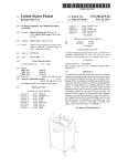
FIG. 1 is a perspective view of a shredder constructed in
It is an aspect of the invention to provide a shredder that
does not jam as a result of too many papers, or an article that 60 accordance with an embodiment of the present invention;
is too thick, being fed into the shredder.
FIG. 2 is an exploded perspective view of the shredder of
FIG. 1;
In an embodiment, a shredder is provided. The shredder
includes a housing having a throat for receiving at least one
article to be shredded, and a shredder mechanism received in
the housing. The shredder mechanism includes an electrically
powered motor and cutter elements. The shredder mechanism
enables the at least one article to be shredded to be fed into the
65
FIG. 3 is a schematic illustration of an oiling mechanism in
accordance with an embodiment of the present invention;
FIG. 4 is a perspective view of a shredder having an oiling
mechanism in accordance with an embodiment of the present
invention;
US RE44,161E
3
4
FIG. 5 is a perspective vieW of a shredder having an oiling
mechanism in accordance With an embodiment of the present
The shredder 10 also includes the shredder housing 14,
mentioned above. The shredder housing 14 includes top Wall
24 that sits atop the container 12. The top Wall 24 is molded
from plastic and an opening 26 is located at a front portion
thereof. The opening 26 is formed in part by a doWnWardly
invention;
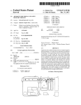
FIG. 6 is a schematic of interaction betWeen a controller
and other parts of the shredder;
depending generally U-shaped member 28. The U-shaped
FIG. 7 is a schematic of an embodiment of an indicator
member 28 has a pair of spaced apart connector portions 27
on opposing sides thereof and a hand grip portion 28 extend
located on the shredder;
FIG. 8 is a schematic of an embodiment of a detector
ing betWeen the connectorportions 27 in spaced apart relation
con?gured to detect a thickness of a article to be shredded by
from the housing 14. The opening 26 alloWs Waste to be
the shredder;
discarded into the container 12 Without being passed through
FIG. 9 is a schematic of another embodiment of a detector
con?gured to detect a thickness of a article to be shredded by
the shredder mechanism 16, and the member 28 may act as a
handle for carrying the shredder 10 separate from the con
tainer 12. As an optional feature, this opening 26 may be
provided With a lid, such as a pivoting lid, that opens and
the shredder;
FIG. 10 is a schematic of another embodiment of a detector
con?gured to detect a thickness of a article to be shredded by
closes the opening 26. HoWever, this opening in general is
optional and may be omitted entirely. Moreover, the shredder
the shredder;
FIG. 11 is a schematic of another embodiment of the detec
tor of FIG. 10; and
FIG. 12 is a How diagram of an embodiment of a method
20
for shredding an article.
DETAILED DESCRIPTION OF THE INVENTION
FIGS. 1 and 2 illustrate a shredder constructed in accor
25
through Which the shredder mechanism 16 discharges shred
ded articles into the container 12.
dance With an embodiment of the present invention. The
shredder is generally indicated at 10. In the illustrated
embodiment, the shredder 10 sits atop a Waste container,
The top Wall 24 has a generally laterally extending open
generally indicated at 12, Which is formed of molded plastic
or any other material. The shredder 10 illustrated is designed
speci?cally for use With the container 12, as the shredder
housing 14 and its top Wall 24 may have any suitable con
struction or con?guration.
The shredder housing 14 also includes a bottom receptacle
30 having a bottom Wall, four side Walls and an open top. The
shredder mechanism 1 6 is received therein, and the receptacle
30 is a?ixed to the underside of the top Wall 24 by fasteners.
The receptacle 30 has an opening 32 in its bottom Wall
30
ing, Which is often referred to as a throat 36, extending gen
erally parallel and above the cutter elements. The throat 36
enables the articles being shredded to be fed into the cutter
elements. As can be appreciated, the throat 36 is relatively
housing 14 sits on the upper periphery of the Waste container
narrow, Which is desirable for preventing overly thick items,
12 in a nested relation. HoWever, the shredder 10 may also be
designed so as to sit atop a Wide variety of standard Waste
containers, and the shredder 10 Would not be sold With the
such as large stacks of documents, from being fed into cutter
elements, Which could lead to jamming. The throat 36 may
35
container. LikeWise, the shredder 10 could be part of a large
freestanding housing, and a Waste container Would be
enclosed in the housing. An access door Would provide for
access to and removal of the container. Generally speaking,
the shredder 10 may have any suitable construction or con
The top Wall 24 also has a sWitch recess 38 With an opening
therethrough. An on/off sWitch 42 includes a sWitch module
(not shoWn) mounted to the top Wall 24 underneath the recess
38 by fasteners, and a manually engageable portion 46 that
40
?guration and the illustrated embodiment is not intended to
be limiting in any Way. In addition, the term “shredder” is not
intended to be limited to devices that literally “shred” docu
ments and articles, but is instead intended to cover any device
that destroys documents and articles in a manner that leaves
each document or article illegible and/or useless.
As shoWn in FIG. 2, in an embodiment, the shredder 10
includes a shredder mechanism 16 that includes an electri
moves laterally Within the recess 38. The sWitch module has
a movable element (not shoWn) that connects to the manually
engageable portion 46 through the opening. This enables
movement of the manually engageable portion 46 to move the
45
sWitch module betWeen its states.
In the illustrated embodiment, the sWitch module connects
the motor 18 to the poWer supply. Typically, the poWer supply
cally poWered motor 18 and a plurality of cutter elements 19.
“Shredder mechanism” is a generic structural term to denote
a device that destroys articles using at least one cutter ele
have any con?guration.
50
Will be a standard poWer cord 44 With a plug 48 on its end that
plugs into a standard AC outlet. The sWitch 42 is movable
betWeen an on position and an off position by moving the
portion 46 laterally Within the recess 38. In the on position,
contacts in the sWitch module are closed by movement of the
ment. Such destroying may be done in any particular Way. For
manually engageable portion 46 and the movable element to
example, the shredder mechanism may include at least one
enable a delivery of electrical poWer to the motor 18. In the off
position, contacts in the sWitch module are opened to disable
the delivery of electric poWer to the motor 18.
As an option, the sWitch 42 may also have a reverse posi
tion Wherein contacts are closed to enable delivery of electri
cutter element that is con?gured to punch a plurality of holes
in the document or article in a manner that destroys the
document or article. In the illustrated embodiment, the cutter
elements 19 are generally mounted on a pair of parallel rotat
55
ing shafts 20. The motor 18 operates using electrical poWer to
rotatably drive the shafts and the cutter elements through a
conventional transmission 23 so that the cutter elements shred
cal poWer to operate the motor 18 in a reverse manner. This
Would be done by using a reversible motor and applying a
60
articles fed therein. The shredder mechanism 16 may also
include a sub-frame 21 for mounting the shafts, the motor 18,
and the transmission 23. The operation and construction of
tion for clearing jams. In the illustrated embodiment, in the
off position the manually engageable portion 46 and the mov
such a shredder mechanism 16 are Well knoWn and need not
be described herein in detail. Generally, any suitable shredder
mechanism 1 6 knoWn in the art or developed hereafter may be
used.
current that is of a reverse polarity relative to the on position.
The capability to operate the motor 18 in a reversing manner
is desirable to move the cutter elements in a reversing direc
65
able element Would be located generally in the center of the
recess 38, and the on and reverse positions Would be on
opposing lateral sides of the off position.
US RE44,161 E
6
5
Generally, the construction and operation of the switch 42
The pump 82 communicates through a series of conduits
for controlling the motor 42 are Well known and any construc
tion for such a sWitch 42 may be used.
In the illustrated embodiment, the top cover 24 also
includes another recess 50 associated With an optional sWitch
88 to one or more noZZles 90 that are positioned proximate the
cutter elements 19. In one embodiment, the noZZles can be
positioned such that oil forced through the noZZles is dis
persed as sprayed droplets in the throat of the shredder 10. In
another embodiment, the oil is dispersed in back of the throat
of the shredder 10. Generally, the noZZles have openings
lock 52. The sWitch lock 52 includes a manually engageable
portion 54 that is movable by a user’s hand and a locking
small relative to the conduits, thereby creating a high speed
portion (not shoWn). The manually engageable portion 54 is
?oW at the noZZle, alloWing the oil to be expelled at a predict
able rate and pattern.
seated in the recess 50 and the locking portion is located
beneath the top Wall 24. The locking portion is integrally
formed as a plastic piece With the manually engageable por
As shoWn in FIG. 4, a system in accordance With an
embodiment of the present invention may be a retro?t device.
In this embodiment, the reservoir 84 is mounted to an outside
surface of the shredder 10. It is connected via a conduit 92 to
the main unit 94. The main unit 94 may include a poWer
tion 54 and extends beneath the top Wall 24 via an opening
formed in the recess 50.
The sWitch lock 52 causes the sWitch 42 to move from
either its on position or reverse position to its off position by
supply (not shoWn) and the pump 82 (not shoWn in FIG. 4). In
a camming action as the sWitch lock 52 is moved from a
ing position, the movable element of the sWitch 42 is
any embodiment, the reservoir 84 may be designed to be
removed and replaced, rather than re-?lled.
An alternate embodiment includes the system 80 built into
the housing of the shredder 10. In this embodiment, shoWn in
FIG. 5, the ?ll neck 86 can be designed to extend through the
top Wall 24 of the shredder housing 14. Operation of the
restrained in its off position against movement to either its on
system 80 does not depend on Whether it is retro?t or built-in.
releasing position to a locking position. In the releasing posi
tion, the locking portion is disengaged from the movable
element of the sWitch 42, thus enabling the sWitch 42 to be
moved betWeen its on, off, and reverse positions. In the lock
20
or reverse position by the locking portion of the sWitch lock
52.
25
Preferably, but not necessarily, the manually engageable
determining When to lubricate the cutter elements 19. The
controller processes the instructions and subsequently
applies them by activating the pump 82 to cause ?uid from the
portion 54 of the sWitch lock 52 has an upWardly extending
projection 56 for facilitating movement of the sWitch lock 52
betWeen the locking and releasing positions.
One advantage of the sWitch lock 52 is that, by holding the
reservoir to be delivered to the noZZles 90 under pressure. The
30
sWitch 42 in the off position, to activate the shredder mecha
nism 16 the sWitch lock 52 must ?rst be moved to its releasing
noZZles are positioned and arranged to spray the pressurized
lubricating oil to the cutter elements 19. In general, the oil Will
be dispersed in a predetermined pattern directly onto the
position, and then the sWitch 42 is moved to its on or reverse
position. This reduces the likelihood of the shredder mecha
nism 16 being activated unintentionally. Reference may be
made to Us. Patent Application Publication No. 2005
In operation, a controller 96 (shoWn in FIG. 6) for the
lubrication system 80 is programmed With instructions for
35
cutter elements and/ or the strippers. In a particular arrange
ment, it may be useful to array the noZZles beloW the cutter
elements so that lubrication is sprayed from beloW. In an
alternate embodiment, the oil is sprayed onto an intermediate
0218250 A1, Which is incorporated herein by reference, for
surface 98 (shoWn in FIG. 3) and alloWed to drip from there
further details of the sWitch lock 52. This sWitch lock is an
onto the cutter elements 19 and the strippers (Which are gen
erally located on the outWard or post-cutting side of the cut
entirely optional feature and may be omitted.
In the illustrated embodiment, the shredder housing 14 is
40
ting mechanism and include a serrated member or a comb
designed speci?cally for use With the container 12 and it is
intended to sell them together. The upper peripheral edge 60
type member having teeth that protrude into the spaces
betWeen the individual cutting disks). The illustrated embodi
of the container 12 de?nes an upWardly facing opening 62,
ments of the lubrication system 80 are not intended to be
limiting in any Way. Reference may be made to Us. patent
and provides a seat 61 on Which the shredder 10 is removably
mounted. The seat 61 includes a pair of pivot guides 64
45
provided on opposing lateral sides thereof. The pivot guides
rated by reference, for further details of an oiling mechanism.
The lubrication system 80 is an optional feature of the shred
64 include upWardly facing recesses 66 that are de?ned by
Walls extending laterally outWardly from the upper edge 60 of
the container 12. The Walls de?ning the recesses 66 are
molded integrally from plastic With the container 12, but may
50
be provided as separate structures and formed from any other
material. At the bottom of each recess 66 is provided a step
doWn or ledge providing a generally vertical engagement
surface 68. This step doWn or ledge is created by tWo sections
of the recesses 66 being provided With different radii. Refer
application Ser. No. 11/385,864, Which is hereby incorpo
55
der 10.
In an embodiment of the invention, the shredder 10
includes a thickness detector 100 to detect overly thick stacks
of documents or other articles that could jam the shredder
mechanism 16, and communicate such detection to a control
ler 200, as shoWn in FIG. 6. Upon such detection, the con
troller 200 may communicate With an indicator 110 that pro
vides a Warning signal to the user, such as an audible signal
ence may be made to Us. Pat. No. 7,025,293, Which is
and/or a visual signal. Examples of audible signals include,
incorporated herein by reference, for further details of the
but are not limited to beeping, buZZing, and/or any other type
of signal that Will alert the user that the stack of documents or
other article that is about to be shredded is above a predeter
pivotal mounting. This pivotal mounting is entirely optional
and may be omitted.
As schematically illustrated in FIG. 3, in order to lubricate
the cutter elements 19 of the shredder 10, a lubrication system
80 may be included for providing lubrication at the cutter
elements 19. The system includes a pump 82, that draWs
lubricating ?uid, such as oil, from a reservoir 84. In a typical
application, the reservoir 84 Will have a ?ll neck 86 that
extends through the top Wall 24 of the shredder housing 14 to
alloW for easy access for re?lling the reservoir (see FIG. 5).
60
mined maximum thickness and may cause the shredder
mechanism 16 to jam. This gives the user the opportunity to
reduce the thickness of the stack of documents or reconsider
forcing the thick article through the shredder, knoWing that
65
any such forcing may jam and/ or damage the shredder.
A visual signal may be provided in the form of a red
Warning light, Which may be emitted from an LED. It is also
contemplated that a green light may also be provided to
US RE44,161 E
7
8
indicate that the shredder 1 0 is ready to operate. In an embodi
ment, the indicator 110 is a progressive indication system that
includes a series of indicators in the form of lights to indicate
the thickness of the stack of documents or other article rela
tive to the capacity of the shredder is provided, as illustrated
maximum thickness, the series of “beeps” may be continu
ous, thereby indicating to the user that such a threshold has
been met and that the thickness of the article to be shredded
should be reduced.
The visual and audible signals may be used together in a
single device. Also, other Ways of indicating progressive
in FIG. 7. As illustrated, the progressive indication system
includes a green light 112, a plurality of yelloW lights 114,
and a red light 116. The green light 112 indicates that the
thicknesses of the items inserted in the throat 36 may be used.
detected thickness of the item (eg a single paper, a stack of
the detected thickness increases may be used. Also, a “fuel
papers, a compact disc, a credit card, etc.) that has been placed
in the throat 36 of the shredder 10 is beloW a ?rst predeter
mined thickness and Well Within the capacity of the shredder.
The yelloW lights 114 provide a progressive indication of the
thickness of the item. The ?rst yelloW light 114, located next
to the green light 112, Would be triggered When the detected
thickness is at or above the ?rst predetermined thickness, but
beloW a second predetermined thickness that triggers the red
light 116. If there is more than one yelloW light 114, each
additional yelloW light 114 may correspond to thicknesses at
or above a corresponding number of predetermined thick
nesses betWeen the ?rst and second predetermined thick
gauge,” i.e., a dial With a pivoting needle moving progres
nesses. The yelloW lights 114 may be used to train the user
into getting a feel for hoW many documents should be shred
ded at one time. The red light 116 indicates that the detected
thickness is at or above the second predetermined thickness,
Which may be the same as the predetermined maximum thick
ness, thereby Warning the user that this thickness has been
reached.
The sequence of lights may be varied and their usage may
vary. For example, they may be arranged linearly in a
For example, an LCD screen With a bar graph that increases as
sively betWeen Zero and a maximum desired thickness, may
also be used. As discussed above, With an audible signal, the
number or frequency of the intermittent audible noises may
increase along With the detected thickness. The invention is
not limited to the indicators described herein, and other pro
gressive (i.e., corresponding to multiple predetermined thick
ness levels) or binary (i.e., corresponding to a single prede
termined thickness) indicators may be used.
The aforementioned predetermined thicknesses may be
20
the toughest article expected to be inserted into the shredder,
25
compact disc (i.e., 1.2 mm). It is estimated that such a thick
30
ness Would also correspond to about 12 sheets of 20 lb. paper.
Second, a margin for error may also be factored in. For
example in the example given, the predetermined maximum
thickness may be set to a higher thickness, such as to 1.5 mm,
35
a useful sequence because of most people’s familiarity With
tra?ic lights. LikeWise, a plurality of green lights (or any other
color) could be used to progressively indicate the detected
thickness Within a range. Each light Would be activated upon
the detected thickness being equal to or greater than a corre
such as a compact disc, Which is made from polycarbonate. If
it is knoWn that the shredder mechanism may only be able to
handle one compact disc at a time, the predetermined maxi
mum thickness may be set to the standard thickness of a
sequence as shoWn, or in other con?gurations (e. g. in a partial
circle so that they appear like a fuel gauge or speedometer.
Also, for example, the yelloW light(s) 114 may be lit only for
thickness(es) close to (i.e., Within 25% of) the predetermined
maximum thickness, Which triggers the red light 116. This is
determined as folloWs. First, because the actual maximum
thickness that the shredder mechanism may handle Will
depend on the material that makes up the item to be shredded,
the maximum thickness may correspond to the thickness of
Which Would alloW for approximately an additional 3 sheets
of paper to be safely inserted into the shredder (but not an
additional compact disc). Of course, these examples are not
intended to be limiting in any Way.
For shredders that include separate throats for receiving
40
sheets of paper and compact discs and/ or credit cards, a
detector 100 may be provided to each of the throats and
sponding predetermined thickness. A red (or other color) light
con?gured for different predetermined maximum thick
may be used at the end of the sequence of lights to emphasiZe
that the predetermined maximum thickness has been reached
or exceeded (or other Ways of getting the user’s attention may
be used, such as emitting an audible signal, ?ashing all of the
lights in the sequence, etc.). These alert features may be used
in lieu of or in conjunction With cutting off poWer to the
nesses. For example, the same shredder mechanism may be
able to handle one compact disc and 18 sheets of 20 lb. paper.
Accordingly, the predetermined maximum thickness associ
45
about 1.5 mm (0.3 mm above the standard thickness of a
compact disc), While the predetermined maximum thickness
shredder mechanism upon detecting that the predetermined
maximum thickness has been reached or exceeded.
Similarly, the aforementioned indicators of the progressive
indicator system may be in the form of audible signals, rather
than visual signals or lights. For example, like the yelloW
lights described above, audible signals may be used to pro
50
associated With the detector associated With the throat that is
speci?cally designed to receive sheets of paper may be set to
about 1.8 mm. Of course, these examples are not intended to
be limiting in any Way and are only given to illustrate features
of embodiments of the invention.
Similarly, a selector sWitch may optionally be provided on
vide a progressive indication of the thickness of the item. The
audible signals may vary by number, frequency, pitch, and/or
ated With the detector associated With the throat that is spe
ci?cally designed to receive compact discs may be set to
55
the shredder to alloW the user to indicate What type of material
is about to be shredded, and, hence the appropriate predeter
volume in such a Way that provides the user With an indication
of hoW close the detected thickness of the article is to the
mined maximum thickness for the detector. A given shredder
predetermined maximum thickness. For example, no signal
mechanism may be able to handle different maximum thick
nesses for different types of materials, and the use of this
selector sWitch alloWs the controller to use a different prede
or a single “beep” may be provided When the detected thick
ness is Well beloW the predetermined maximum thickness,
and a series of “beeps” that increase in number (eg more
“beeps” the closer the detection is to the predetermined maxi
mum thickness) and/or frequency (e.g. less time betWeen
beeps the closer the detection is to the predetermined maxi
mum thickness) as the detected thickness approaches the
predetermined maximum thickness may be provided. If the
detected thickness is equal to or exceeds the predetermined
60
termined thickness for the material selected. For example,
there may be a setting for “paper,” “compact discs,” and/or
“credit cards,” as these materials are knoWn to have different
65
cutting characteristics and are popular items to shred for
security reasons. Again, based on the capacity of the shredder
mechanism, the appropriate predetermined maximum thick
nesses may be set based on the knoWn thicknesses of the items
US RE44,161E
9
10
to be shredded, Whether it is the thickness of a single compact
engage a top side 134 of the contact member 120. Because the
disc or credit card, or the thickness of a predetermined num
ber of sheets of paper of a known Weight, such as 20 lb. The
top side 134 of the contact member 120 is sloped, the contact
member 120 Will move against the bias of the spring 128 and
into contact With the pieZoelectric sensor 124, thereby caus
ing a voltage to be created Within the pieZoelectric sensor 124.
selector sWitch is an optional feature, and the description
thereof should not be considered to be limiting in any Way.
Returning to FIG. 6, in addition to the indicator 110 dis
cussed above, the detector 100 may also be in communication
With the motor 18 that poWers the shredder mechanism 16 via
the controller 200. Speci?cally, the controller 200 may con
trol Whether poWer is provided to the motor 18 so that the
shafts 20 may rotate the cutter elements 19 and shred the item.
This Way, if the thickness of the item to be shredded is
detected to be greater than the capacity of the shredder
mechanism 16, poWer Will not be provided to the shredder
As the thickness of the item increases, the force applied by the
contact member 120 to the pieZoelectric sensor 124 increases,
thereby increasing the voltage generated Within the pieZo
electric sensor 124. The resulting voltage may be communi
cated to the controller 200 or directly to the indicator 110,
thereby causing the indicator 110 to indicate that the item is
above the predetermined maximum thickness. In addition,
the controller, upon sensing the voltage, may prevent poWer
from poWering the motor 18 to drive the shafts 20 and cutter
mechanism 16, thereby making the shredder 10 temporarily
elements 19. Of course, different con?gurations of the pieZo
inoperable. This not only protects the motor 18 from over
load, it also provides an additional safety feature so that items
that should not be placed in the shredder 10 are not able to
electric sensor 124 and contact member 120 may be used. The
illustrated embodiment is not intended to be limiting in any
Way.
In another embodiment, illustrated in FIG. 10, the detector
pass through the shredder mechanism 16, even though they
may ?t in the throat 36 of the shredder 10.
FIGS. 8-11 shoW different embodiments of the detector
100 that may be used to detect the thickness of an article (eg
20
a compact disc, credit card, stack of papers, etc.) that is placed
in the throat 36 of the shredder. As shoWn in FIG. 8, the
detector 100 may include a contact member 120 that is
mounted so that it extends into the throat 36 at one side
25
thereof. The contact member 120 may be pivotally mounted
or it may be mounted Within a slot so that it translates relative
to the throat 36. The contact member 120 is mounted so that
as the item to be shredded is inserted into the throat 36, the
item engages the contact member 120 and causes the contact
100 includes the contact member 120 and an optical sensor
140. In this embodiment, the contact member 120 is pivotally
mounted such that one portion extends into the throat 36 and
another portion, Which has a plurality of rotation indicators
142, extends aWay from the throat 36. The optical sensor 140
30
may be con?gured to sense the rotation indicators 142 as the
rotation indicators 142 rotate past the optical sensor 140. For
example, the optical sensor 140 may include an infrared LED
144 and a dual die infrared receiver 146 to detect the direction
and amount of motion of the contact member 120. As shoWn
in FIG. 7, the contact member 120 may be con?gured such
that a small amount of rotation of the contact member is
member 120 to be pushed out of the Way of the item. As shoWn
ampli?ed at the opposite end of the contact member 120,
in FIG. 8, a strain gauge 122 is located on a side of the contact
thereby improving the sensor’ s ability to sense changes in the
member 120 that is opposite the throat 36. The strain gauge
122 is positioned so that it engages the contact member 120
thickness of the items that cause the contact member 120 to
35
rotate. Of course, different con?gurations of the optical sen
40
sor 140 and contact member 120 may be used. The illustrated
embodiment is not intended to be limiting in any Way.
Another embodiment of the detector 100 that includes the
optical sensor 140 is shoWn in FIG. 11. As illustrated in FIG.
8, the detector 100 is located above an infrared sensor 150 that
45
may be used. The illustrated embodiment is not intended to be
limiting in any Way. The sensor 150 provides a signal to the
controller 200, Which in turn is communicated to the motor
18. When the sensor 150 senses that an article is passing
and is able to measure the displacement of the contact mem
ber 120 relative to the throat 36. Other displacement sensors
may be used. The greater the displacement, the thicker the
item being inserted into the throat 36. The strain gauge 122
communicates this measurement to the controller 200 and the
controller 200 determines Whether the displacement mea
detects the presence of an article. Of course, any such sensor
sured by the strain gauge 122, and hence thickness of the item,
is greater than the predetermined maximum thickness,
thereby indicating that the item that is being fed into the throat
of the shredder 10 Will cause the shredder mechanism 16 to
jam. If the detected thickness is greater than the predeter
through a loWer portion of the throat 36, the controller 200
signals the motor 18 to start turning the shafts 20 and cutter
mined maximum thickness, the controller 200 may send a
signal to the indicator 110, as discussed above, and/or prevent
poWer from poWering the motor 18 to drive the shafts 20 and
cutter elements 19. This Way, a jam may be prevented. Like
Wise, the measured displacement of the contact member 120
50
may be used by the controller 200 to output progressive
amounts of thicknesses, as discussed above. Of course, dif
ferent con?gurations of the strain gauge 122 and contact
member 120 may be used. The illustrated embodiment is not
intended to be limiting in any Way.
mechanism 16 to operate. Of course, this particular con?gu
55
100 includes the contact member 120 and a pieZoelectric
sensor 124. In this embodiment, the contact member 120 is
or article being fed into the throat 36 of the shredder 10. For
60
example, embodiments utiliZing eddy current, inductive,
photoelectric, ultrasonic, Hall effect, or even infrared prox
imity sensor technologies are also contemplated and are con
sidered to be Within the scope of the present invention.
The sensors discussed above, and other possible sensors,
to bias the contact member 120 into the throat 36. The nar
roWer opening that is created by a tip 130 of the contact
member 120 and a Wall 132 opposite the spring 128 is less
than the predetermined maximum thickness. Therefore, if an
item that is too thick to be shredded enters the throat 3 6, it Will
ration is not intended to be limiting in any Way.
Although various illustrated embodiments herein employ
particular sensors, it is to be noted that other approaches may
be employed to detect the thickness of the stack of documents
In another embodiment, illustrated in FIG. 9, the detector
mounted such that it protrudes through one Wall 126 of the
throat and into the throat by a small amount, thereby creating
a slightly narroWer throat opening. A spring 128 may be used
elements 19. Of course, because the detector 100 is also in
communication With the controller 200, if the detector 100
detects that the thickness of the article that has entered the
throat is too thick for the capacity of the shredder mechanism
16, the shredder mechanism 16 may not operate, even though
the sensor 150 has indicated that it is time for the shredder
65
may also be used to initiate the shredding operation by
enabling the poWer to be delivered to the motor of the shred
der mechanism. This use of sensors in the shredder throat is
US RE44,161E
11
12
known, and they allow the shredder to remain idle until an
item is inserted therein and contacts the sensor, Which in turn
enables poWer to operate the motor to rotate the cutting ele
ments via the shafts. The controller 200 may be con?gured
such that the insertion of an item Will perform this function of
thickness. The predetermined maximum thickness may be
based on the capacity of the shredder mechanism 16, as
discussed above. If the controller 200 determines that the
thickness that has been detected is at least the predetermined
enabling poWer delivery to operate the shredder mechanism
maximum thickness, at 310, a Warning is provided. For
example, to provide the Warning, the controller 200 may
motor. The motor may be cut-off or not even started if the
cause the red light 116 to illuminate and/ or causes an audible
thickness exceeds the predetermined maximum thickness.
Returning to FIG. 6, for embodiments of the shredder 10
that include the lubrication system 80, the controller 200 may
signal to sound and/or cause poWer to be disrupted to the
motor 18 so that the shredder mechanism 16 Will not shred the
item. The user should then remove the item from the throat 36
be programmed to communicate With the controller 96 asso
ciated With the lubrication system 80 to operate the pump 82
in a number of different modes. The controller 200 and the
controller 96 may be part of the same controller, or may be
separate controllers that communicate With each another. In
one embodiment, the controller 96 is programmed to operate
of the shredder 10 at 312, and reduce the thickness of the item
at 314 before inserting the item back into the throat 36 at 304.
If the controller 200 determines that the thickness that has
been detected is less than the predetermined maximum thick
ness, the controller 200 may cause the green light 112 to
illuminate and/ or alloWs poWer to be supplied to the shredder
mechanism 16 so that the shredder 10 may proceed With
shredding the item at 316.
according to a predetermined timing schedule. In another, the
controller 96 activates the pump upon a certain number of
rotations of the drive for the cutter elements. In another
embodiment, the detector 100 at the throat 36 of the shredder
20
10 monitors the thickness of items deposited therein. Upon
accumulation of a predetermined total thickness of material
shredded, the controller 96 activates the pump to lubricate the
cutter elements 19. For example, if the predetermined total
thickness of material is programmed in the controller 96 to be
0.1 m (100 mm), then once the total accumulated detected
thickness of articles that have been shredder is at least equal
about the predetermined maximum thickness, the controller
25
to 0.1 m (e.g., one hundred articles With an average thickness
of 1 mm, or ?fty articles With an average thickness of 2 mm,
etc.), the controller 96 Will activate the pump 82 of the lubri
cation system 80 to lubricate the cutter elements 19.
It is also possible to schedule the lubrication based on a
number of uses of the shredder (e.g., the controller tracks or
counts the number of shredding operations and activates the
pump after a predetermined number of shredder operations).
30
35
In each of the embodiments making use of accumulated mea
sures, a memory 97 can be incorporated for the purpose of
tracking use. Although the memory 97 is illustrated as being
part of the controller 96 associated With the lubrication sys
tem, the memory may be part of the shredder controller 200,
40
illustrated embodiment is not intended to be limiting in any
Way.
45
articles that have been shredded) may be used to alert the user
that maintenance should be completed on the shredder. The
alert may come in the form of a visual or audible signal, such
as the signals discussed above, or the controller may prevent
poWer from poWering the shedder mechanism until the main
tenance has been completed.
The ability to keep track of the accumulated use of the
shredder may also be helpful in a Warranty context, Where the
Warranty could be based on the actual use of the shredder,
rather than time. This is similar to the Warranties that are used
With automobiles, such as “100,000 miles or 10 years, Which
ever comes ?rst.” For example, the Warranty may be based on
of documents, as the shredder mechanism 16 is shredding the
previous item that Was fed into the throat 3 6 of the shredder at
3 04. If the user does insert an additional item into the throat 36
at 318, the method returns to 304, and the detector 100 detects
the thickness of the item at the location of the detector 100 at
306, and so on. If part of the previous item is still in the throat
36, the cumulative thickness of the item being shredder and
the neW item may be detected. If the user does not add an
additional item at 318, the method ends at 320. The illustrated
method is not intended to be limiting in any Way.
The foregoing illustrated embodiments have been provided
50
to illustrate the structural and functional principles of the
present invention and are not intended to be limiting. To the
contrary, the present invention is intended to encompass all
modi?cations, alterations and substitutions Within the spirit
and scope of the appended claims.
55
What is claimed is:
[1. A shredder comprising:
a housing having a throat open to an exterior of the housing
100 uses or one year, Whichever comes ?rst, or the Warranty
may be based on shredding paper having a total sensed thick
for permitting a user to feed at least one article to be
ness of 1 meter or 2 years, Whichever comes ?rst, and so on. 60
FIG. 12 illustrates a method 300 for detecting the thickness
of an item, eg a stack of documents or an article, being fed
into the throat 36 of the shredder 10. The method starts at 302.
At 304, the item is fed into the throat 36 of the shredder 10. At
306, the detector 100 detects the thickness of the item. At 308,
the controller 200 determines Whether the thickness that has
been detected is greater than a predetermined maximum
200 may cause one of the yelloW lights to illuminate, depend
ing on hoW close to the predetermined maximum thickness
the detected thickness is. For example, the different yelloW
lights may represent increments of about 0.1 mm so that if the
detected thickness is Within 0.1 mm of the predetermined
maximum thickness, the yelloW light 114 that is closest to the
red light 116 illuminates, and so on. Although poWer Will still
be supplied to the shredder mechanism 16, the user Will be
Warned that that particular thickness is very close to the
capacity limit of the shredder 10. Of course, any increment of
thickness may be used to cause a particular yelloW light to
illuminate. The example given should not be considered to be
limiting in any Way.
Returning to the method 300 ofFIG. 9, at 318, the user may
insert an additional item, such as another document or stack
or may be located on some other part of the shredder 10. The
In addition, the accumulated measures (eg the number of
shredding operations or the accumulated thickness of the
In the embodiment that includes the plurality of yelloW
lights 114 as part of the indicator 100, if the controller 200
determines that the thickness that has been detected is less
than the predetermined maximum thickness, but close to or
shredded;
a shredder mechanism received in the housing and includ
ing an electrically poWered motor and cutter elements,
65
the shredder mechanism enabling the at least one article
fed into the throat to be shredded to be fed into the cutter
elements and the motor being operable to drive the cutter
elements in a shredding direction so that the cutter ele
ments shred the articles fed therein;
US RE44,161 E
14
13
a thickness detector con?gured to detect a thickness
article to be shredded being received by the throat, and
betWeen opposing major surfaces of the at least one
Wherein the controller is con?gured to operate the motor to
article to be shredded being received by the throat;
drive the cutter elements in the shredding direction responsive
a maximum thickness indicator having a visual or audible
output and con?gured to indicate a visual or audible
signal to a user of the shredder via the visual or audible
to the detector detecting both the presence of the at least one
article to be shredded being received by the throat and that the
thickness thereof is less than the predetermined maximum
output;
thickness.]
a controller con?gured to actuate the maximum thickness
indicator and indicate the visual or audible signal to the
user via the visual or audible output responsive to the
detector detecting that the thickness of the at least one
article is at least equal to a predetermined maximum
[14. A shredder according to claim 1, Wherein the detector
is a thickness detector and the shredder further comprises a
presence detector con?gured to detect a presence of the at
least one article to be shredded being received by the throat,
Wherein the controller is con?gured to operate the motor to
drive the cutter elements in the shredding direction
responsive to the presence detector detecting the pres
thickness.]
[2. A shredder according to claim 1, Wherein the maximum
thickness indicator includes a light that is illuminated to indi
ence of the at least one article to be shredded being
cate the signal to the user.]
[3. A shredder according to claim 1, Wherein the maximum
received by the throat.]
[15. A shredder according to claim 14, Wherein the con
indicator includes an audible alarm that audibly indicates the
troller is con?gured to operate the motor to drive the cutter
signal to the user.]
[4. A shredder according to claim 1, Wherein the controller
is also con?gured to prevent the motor from driving the cutter
elements in the shredding direction responsive to the detector
20
article to be shredded being received by the throat and the
thickness sensor detecting that the thickness thereof is less
detecting that the thickness of the at least one article is at least
equal to the predetermined maximum thickness.]
[5. A shredder according to claim 1, Wherein the maximum
elements in the shredding direction responsive to both the
presence detector detecting the presence of the at least one
than the predetermined maximum thickness.]
25
thickness indicator is included in a progressive indicator sys
16. A shredder comprising:
a housing having a throat open to an exterior ofthe housing
tem coupled to the controller,
Wherein the progressive indicator system is con?gured to
for permitting a user to feed at least one article to be
indicate a detected thickness of the at least one article
a shredder mechanism received in the housing and includ
Within a range of thicknesses up to and including the
shredded;
30
predetermined maximum thickness.]
[6. A shredder according to claim 5, Wherein the progres
fed into the throat to be shredded to befed into the cutter
elements and the motor being operable to drive the
sive indicator system has a plurality of indicators, Wherein
each indicator is associated With a corresponding predeter
mined thickness of the at least one article Within said range,
cutter elements in a shredding direction so that the cutter
35
the plurality of indicators including the maximum thickness
indicator corresponding to the predetermined maximum
between opposing major surfaces of the at least one
article to be shredded being received by the throat;
40
determined thickness based on the detector detecting
equal to the corresponding predetermined thickness.]
45
thickness;
throat.]
wherein the detector is a thickness detector and the shred
50
further comprises a strain gauge con?gured to measure move
ment of the contact member and communicate the movement
ded being received by the throat, wherein the controller
is configured to operate the motor to drive the cutter
55
elements in the shredding direction only in response to
both the presence detector detecting the presence ofthe
60
at least one article to be shredded being received by the
throat and the thickness detector detecting that the thick
ness thereof is less than the predetermined maximum
thickness.
1 7. A shredder according to claim 16, wherein the detector
65
comprises a contact member that extends into the throat and
is actuated in response to the article being inserted into the
throat.
movement to the controller.]
[12. A shredder according to claim 11, Wherein the optical
sensor comprises an infrared LED and a dual die infrared
receiver con?gured to detect the direction and amount of the
movement.]
[13. A shredder according to claim 1, Wherein the detector
is also con?gured to detect a presence of the at least one
elements in the shredding direction responsive to the
presence detector detecting the presence of the at least
one article to be shredded being received by the throat;
wherein the controller starts the motor to drive the cutter
movement to the controller.]
[11. A shredder according to claim 8, Wherein the detector
further comprises an optical sensor con?gured to measure
movement of the contact member and communicate the
derfurther comprises a presence detector configured to
detect a presence of the at least one article to be shred
to the controller.]
[10. A shredder according to claim 8, Wherein the detector
further comprises a pieZoelectric sensor con?gured to mea
sure movement of the contact member and communicate the
a controller configured to actuate the maximum thickness
indicator and indicate the visual or audible signal to the
user via the visual or audible output responsive to the
detector detecting that the thickness of the at least one
article is at least equal to a predetermined maximum
comprises a contact member that extends into the throat and
is actuated in response to the article being inserted into the
[9. A shredder according to claim 8, Wherein the detector
a maximum thickness indicator having a visual or audible
output and configured to indicate a visual or audible
signal to a user ofthe shredder via the visual or audible
output;
that the thickness of the at least one article is at least
[7. A shredder according to claim 6, Wherein the progres
sive indicator system comprises a plurality of lights.]
[8. A shredder according to claim 1, Wherein the detector
elements shred the articles fed therein;
a thickness detector configured to detect a thickness
thickness,
Wherein the progressive indicator system activates the indi
cator associated With its respective corresponding pre
ing an electrically powered motor and cutter elements,
the shredder mechanism enabling the at least one article