1
US008382019B2
(12) Ulllted States Patent
(10) Patent N0.:
Romanovich et a].
(54)
(45) Date of Patent:
IN-RUSH CURRENT JAM PROOF SENSOR
4,378,717 A
4,489,897 A
4,495,456 A
_
_
(75) Inventors: Dmltry Romanovlch, Wheaton, IL
(US); Michael Dale Jensen, Wood Dale,
IL (US)
'
_
( ) Not1ce.
Feb. 26, 2013
4/1983 Schneider et a1
12/1984 Turner
1/1985 Vercillo et a1.
4,497,478 A
2/1985
4,683,381 A
7/1987 Dufoug
(Continued)
Reschenhofer
FOREIGN PATENT DOCUMENTS
(73) Ass1gnee: Fellowes, Inc., Itasca, IL (US)
*
US 8,382,019 B2
_
_
_
_
DE
3313232
“M984
DE
86198564
10/1988
Subject‘ to any d1scla1mer, the term of this
(Continued)
patent 1s extended or adjusted under 35
U30 1540)) by 316 days(21)
App1_ NO; 12/772,722
OTHER PUBLICATIONS
Complaint for Declaratory Judgment ?led on Nov. 15, 2010 byRoyal
Applicance Manufacturing Co., d/b/a/ TT] Floor Care North
(22)
Filed;
(65)
May 3, 2010
America and Techtronic Industries Co. Ltd. against Fellowes, Inc.
C t'
d
( on lnue )
Prior Publication Data
Us 2011/0266379 A1
Nov. 3, 2011
Primary Examiner * Bella Miller
(74) Attorney, Agent, or Firm *Pillsbury Winthrop ShaW
(51)
Int. Cl.
B02C 4/32
Pittman LLP
B02C 7/14
(2006.01)
(2006.01)
B 02C 9/04
(2006-01)
(57)
ABSTRACT
52
()
US. Cl. ......................... .. 241/36', 241/100', 241/236
(58)
Field of Classi?cation Search .................. .. 241/33,
A shredder and a method for monitoring a motor of a shredder
ComP~
rlses a h'gh'ghr
ousln
av1n at oat for recelvln
"g an artic
'1 e
and a Shredder mechanism received in the housing for Shred
241/35’ 36’ 100, 236, 27s 30
See application ?le for Complete Search history
ding the article, the mechanism includinganelectrically poW
ered motor and cutter elements, and the motor being operable
to drive the cutter elements in a shredding direction to shred
(56)
References Cited
U.S. PATENT DOCUMENTS
2,221,516 A
4/1937 Hathaway
3,619,537 A
3,724,766 A
3,764,819 A
11/1971 Hosokawaetal.
4/1973 Bosland
10/1973 Muller
3,785,230 A
1/1974 Lokey
3,829,850 A
8/1974 Guetersloh
3,947,734 A
3/1976 Fyler
4,192,467 A
4,352,980 A
3/1980 Hatanaka
10/1982 Hibari
articles. A current sensor for detecting current ?owing
through the motor and a controller coupled to the motor for
controlling operation of the motor are also provided. The
controller is also coupled to the current sensor and con?gured
to detect at least an initial amount of current (or inrush cur
rent) supplied to the motor for each shredding event. Based on
the inrush current, the controller sets a parameter (e.g., over
load or thickness) to prevent overloading or stalling of the
motor, such as caused by a jam or overheating.
22 Claims, 11 Drawing Sheets
US 8,382,019 B2
Page2
US. PATENT DOCUMENTS
4,707,704 A
11/1987 Allen
2004/0194594 A1
10/2004 Dils et al.
2004/0226800 A1
11/2004 Pier a
2005/0046651 A1
3/2005 Askigen etal.
4,757,949 A
7/1988 Horton
2005/0150986 A1
7/2005 Castronovo
4,814,632 A
4,815,669 A
“989 Gl‘ieiser
3/1989 Full‘.
2005/0213106 A1
2006/0016919 A1
9/2005 Weijersetal.
1/2006 Castronovo
4,842,205
4,889,291
4,890,797
4,914,721
5,017,972
5,081,406
5,139,205
5,166,679
A
A
A
A
A
A
A
A
6/1989
12/1989
V1990
4/1990
5/1991
V1992
8/1992
11/1992
Amk‘
Goldhammeretal.
Fullletal'
Glaeser
Daughton
Hughesetal'
Gallagher et al.
Vranish etal.
2006/0054725
2006/009l247
2006/0243631
2007/0007373
2007/0025239
2007/0063082
2007/0080252
2007/0087942
A1
A1
A1
A1
A1
A1
A1
A1
5,167,374 A
12/1992 slrohmeyer
2007/0164135 A1
5,186,398
5,198,777
5,342,033
5,345,138
5,353,468
5,397,890
A
A
A
A
A
A
“993
3/1993
8/1994
9/1994
10/1994
3/1995
2007/0164138
2007/0215728
2007/0221767
2007/0246582
2007/0246586
Zoos/0093487
A1
A1
A1
A1
A1
A1
5,409,171
5,415,355
5,429,313
5,453,644
5,494,229
5,539,322
A
A
A
A
A
A
2008/0231261
2009/0025239
2009/0032629
2009/0090797
2010/0051731
2010/0084496
A1
A1
A1
A1
A1
A1
5,662,280
5,743,521
5,772,129
5,775,605
5,823,529
A
A
A
A
A
2010/0102153
2010/0134805
2010/0170967
2010/0170969
2010/0176227
A1
A1
A1
A1
A1
‘Agnew/J‘
Masuda et a1~
Iwata.
Mukaldono etal'
Yap
Schueleretal.
‘"1995 stangeinberg etal'
5/1995 G0llW1tZ_er
5,850,342 A
7/1995
9/1995
“996
7/1996
9/1997
4/1998
6/1998
7/1998
10/1998
12/1998
Schwelhng
Yap
Rokos.
Z9ug.h1 et a1~
Nlshlo etal'
Munakataetal.
N131?” 6‘ a1~
Tsa‘
Mandel
Nakalnumetal
5,850,588 A *
12/1998 Yoshlkawa .................. .. 399/327
3/2006
500%
11/2006
1/2007
2/2007
3/2007
4/2007
4/2007
Matlin
Matlin
Duke
Matlin
Jain etal.
Coleman
Pierce
Allen
7/2007 Zhong
7/2007
9/2007
9/2007
10/2007
10/2007
400%
Allen
Priester
Matlin
Aries etal.
Matlin etal.
Lee
9/2008 Dengleretal.
1/2009 Pan
2010/0181398 A1
2/2009
4/2009
3/2010
4/2010
4/2010
6/2010
7/2010
7/2010
7/2010
7/2010
Aries etal.
Matlin etal.
Matlin etal.
Matlin etal.
Matlin etal.
Pan
Jensen etal.
Jensen etal.
Davis etal.
Davis etal.
Suedetal‘
2010/0213296 A1
8/2010
5,871,162 A
5,924,637 A
13412716 5
“999 RAJGWSI“
7/1999 Nlederholtmeyer
8/1999 Kroger
2010/0213297 A1
2010/0213300 A1
2010/0243774 A1
8/2010 Suedetal.
8/2010 Matlin etal.
9/2010 Hu etal.
5,942,975 A
D414’l98 s
8/1999 Sorenson
9/1999 Iwata
2010/0252661 A1
2010/0252664 A1
10/2010 Matlln et al.
10/2010 Matlin etal.
5,988,542 A
6,065,696 A
légggg ¥eI¥re°kS°n
D426 805 s
6/2000
A
A
631413883 A
@5888
6’265’682 B1
6,376,939 B1
6418 004 B1
’
24mg;
6’550’70l B1
Sal
IWata
110000 Mitchenetalt
2010/0320299 A1
12/2010 Matllnetal.
7/2001 Lee
4/2002 Suzuki et al.
7/2002 Mth
t l.
2011/0272504 A1
2011/0272505 A1
2011/0280642 A1
11/2011 Matlin et al.
11/2011 Matlinetal.
11/2011 Ikedaetal.
2011/0297769 A1
12/2011 Matlin etal.
2011/0297770 A1
12/2011 Matlin etal.
400% Cfange a
12/2003
1/2004
3/2004
4/2004
10/2004
12/2005
B2
B2
B2
B2
B1
B2
B2
B2
B2
B2
B2
B2
B2
B2
B2
B2
A1
A1
A1
A1
A1
-
11/2010 Caletal.
12/2010 Matlin etal.
6,666,959
6,676,460
6,698,640
6,724,324
6,802,465
6,979,813
6,983,903 B2
11/2010 Chen
2010/0320297 A1
‘ital
500% Yokomine et a1‘
8/2003 Langenecker
12/2003 Peterson
6,997,408
7,025,293
7,040,559
7,166,561
7,210,867
7,213,780
7,311,276
7,520,452
7,624,938
7,631,822
7,631,823
7,631,824
7,635,102
7,661,614
7,663,769
7,712,689
2003/0016365
2003/0042342
2004/0008122
2004/0069883
2004/0159198
10/2010 Chen
2010/0282879 A1
2010/0288861 A1
635613444 B1
6,601,787 B1
6,655,943 B1
B2
B1
B2
B1
B1
B2
2010/0270404 A1
UZoh et al.
Motsenbocker
HakoZaki
Lambert
Norcott et al.
Avril
1/2006 Chang
2/2006
4/2006
5/2006
1/2007
5/2007
5/2007
12/2007
4/2009
12/2009
12/2009
12/2009
12/2009
12/2009
2/2010
2/2010
5/2010
1/2003
3/2003
1/2004
4/2004
8/2004
Watano
Matlin et al.
Matlin
Allen
Silverbrook
Chen
Matlin et al.
Watano et a1.
Aries et al.
Matlin et al.
Matlin et al.
Matlin et al.
Matlin et al.
Matlin et al.
Hayashihara et al.
Matlin et al.
Liess et al.
Kroger et al.
Michael
Watanabe et al.
Peot et al.
FOREIGN PATENT DOCUMENTS
DE
DE
DE
DE
DE
DE
DE
DE
EP
EP
EP
EP
EP
EP
EP
EP
EP
EP
EP
EP
GB
GB
GB
GB
GB
GB
JP
JP
4121330
4207292
4237861
4437348
19835093
202004000907
102006036136
202010001577 U1
268244
0392867
562076
524708
0792691
0818241
856945
855221
1177832
1195202
2180290
2022566
1199903
2171029
2209963
2440651
2442942
2451513
5311911
57-76734
1/1993
1/1993
5/1994
4/1996
2/1999
5/2005
1/2008
11/2010
11/1987
10/1990
9/1992
1/1997
9/1997
1/1998
1/1998
7/1998
2/2002
4/2002
7/2008
2/2009
7/1970
8/1986
6/1989
2/2008
4/2008
2/2009
3/1978
1/1982
US 8,382,019 B2
Page 3
JP
JP
JP
JP
JP
JP
JP
JP
57-070445
57-070445 U
58-223448
59150554
61-000702
62183555
63-173342
2_277560
4/1982
4/1982
12/1983
8/1984
1/1986
11/1987
11/1988
11/1990
g
WO
WO
WO
WO
WO
WO
2005070553
2006019985
2006036370
2007109753
2007122364
2007137761
8/2005
2/2006
4/2006
9/2007
11/2007
12/2007
OTHER PUBLICATIONS
ACCO Rexel, Mainstream 1050/2150/2250/3150/3250 and 3350,
JP
JP
JP
040180852
5.96198
H05-092144
6 / 1992
4/1993
4/ 1993
JP
JP
JP
JP
6-277548
7-299377
8408088
8431861
10/1994
11/1995
4/1996
5/1996
JP
08431962
i;
115V Machines Illustrated Parts Lists and Services Instructions, Mar.
25, 2002, Issue No.4.
ACCO ReXel, Deckside and Of?ce 115V Machines Illustrated Parts
Lists and Service Instructions, Aug. 18, 1999.
ACCO ReXel, Deckside and Of?ce 230V Machines Illustrated Parts
Lists and Service Instructions, Aug. 1, 2000.
GBC Shredmaster Service Manual, Part #6001054, referencing
#996
Models 22305 and 2250X Paper Shredders, Nov. 1997.
?
The Stationary and Business MachinesiJapan, “DS-4000 by Carl
Jimuki K.K.”, Jun. 2003.
JP
968513
2/l997
JP
09075763
3/1997
The Stationary and Business MachinesiJapan, “NSE-501CN by
JP
JP
JP
JP
JP
09-150069
9_262491
10048344
11.216383
11.304942
10/1997
10/1997
2/1998
g/1999
11/1999
Nakabayashi
Oct 2004
International Search Report and Written Opinion for PCT/US2011/
031922 dated Oct. 6,2011.
English Translation of Japanese Patent Application Publication No.
9-38513, published on Feb. 10, 1997.
JP
JP
JP
2000346288
2002_239405
2002239405
12/2000
8/2002
8/2002
U.S. Appl. No. 60/613,750, ?led Sep. 27, 2004, Pierce.
U.S. Appl. No. 60/686,490, ?led May 31, 2005, Pierce.
U.S. Appl. No. 60/688,285, ?led Jun. 7, 2005, Pierce.
JP
2004-321840
11/2004
JP
2004321993
11/2004
* cited by examiner
US. Patent
Feb. 26, 2013
Sheet 1 0f 11
23
FIG. 1
US 8,382,019 B2
US. Patent
Feb. 26, 2013
Sheet 2 0f 11
FIG. 2
US 8,382,019 B2
US. Patent
Feb. 26, 2013
Sheet 3 0f 11
US 8,382,019 B2
44
DETECTOR
42
CONTROLLER
/46
CURRENT SENSOR
34
MOTOR
SHREDDER MECHANISM
/
FIG. 3
2O
US. Patent
Feb. 26, 2013
1%
// /\/ / / /
//"''
21
Sheet 4 0f 11
14
$
(
US 8,382,019 B2
US. Patent
Feb. 26, 2013
Sheet 5 0f 11
US 8,382,019 B2
56
TIME (sec)
3O
5
SHREDDING
EVENT (SET #)
52
FIG. 5
US. Patent
Feb. 26, 2013
Sheet 6 0f 11
US 8,382,019 B2
61
BEGIN SHREDDING EvENT
>
/62
(POWER ON)
‘7
64
DRAW CURRENT USING MOTOR
/
‘V
DETECT INITIAL AMOUNT/INRUSH
CURRENT DRAWN USING CURRENT
66
SENSOR
‘7
SET PARAMETER OF SHREDDER BASED ON
INRUSH CURRENT UsING CONTROLLER
68
‘V
70
END SHREDDING EvENT
A
FIG. 6
/
US. Patent
Feb. 26, 2013
Sheet 7 0f 11
US 8,382,019 B2
72
74
BEGIN SHREDDING EVENT
I
DRAW CURRENT USING MOTOR
/76
I
DETECT INITIAL AMOUNT/INRUSH
CURRENT DRAWN USING CURRENT
78
/
SENSOR
I
SET OVERLOAD DETECTION THRESHOLD
OF SHREDDER BASED ON INRUSH
80
/
CURRENT USING CONTROLLER
I
82
END SHREDDING EVENT
FIG. 7
/
US. Patent
Feb. 26, 2013
Sheet 8 0f 11
US 8,382,019 B2
84
86
—"
BEGIN SHREDDING EVENT
/
DRAW CURRENT USING MOTOR
/
88
V
DETECT INITIAL AMOUNT/INRUSH
90
CURRENT DRAWN USING CURRENT
SENSOR
V
SET THICKNESS OF SHREDDER BASED ON
INRUSH CURRENT USING CONTROLLER
92
/
94
END SHREDDING EVENT
A
FIG. 8
/
US. Patent
Feb. 26, 2013
Sheet 10 0f 11
US 8,382,019 B2
[32*
43K
?\l/lw q\l/lJ
*K
R8 32
2FI L aimSIDM30KNM0_l|_
_|
324
O
R2 W
R14
0.3/1OW
FIG. 10
_W
5
_2+ %
C
H 5 OV
US. Patent
Feb. 26, 2013
i
\LC_C
3
!
i
23 D1
z
;
;
;
i
MOTOR_CURRENT_AC
Sheet 11 0111
US 8,382,019 B2
i
‘M4007
:c4
1, R6
_
+
CAP ‘=31<
.luF
'
D2
K}
5
i
SAFE LINE ;
-
c3 ‘M4007 R5
:
CAP POLL
47uF 25V
:
1
20o
7};
RL-7747-1000
5
E _______________________________________________ "Q51?________________________ -J
US 8,382,019 B2
1
2
IN-RUSH CURRENT JAM PROOF SENSOR
CONTROL
as a motor heats during use, the amount of current being
draWn by the motor tends to decrease, and AC ?uctuations
may occur. This ?rst method is unable to track any decrease in
BACKGROUND OF THE INVENTION
draWn current as the motor heats or ?uctuations. This means
that a “hot” (i.e., Working or rotating) motor Will often stall
before or Without the overload detection circuitry detecting
1. Field of Invention
The present invention relates to shredders for destroying
articles, such as documents, CDs, etc.
2. Description of Related Art
Shredders are Well knoWn devices for destroying substrate
the event.
A second knoWn method for overload detection is a cali
bration that is performed at the factory or during manufacture,
in Which a threshold of a shredder is adjusted to a speci?c load
articles, such as documents, CDs, ?oppy disks, etc. Typically,
(e.g., sheet count) on that speci?c machine. This second
users purchase shredders to destroy sensitive articles, such as
credit card statements With account information, documents
containing company trade secrets, etc.
method may be effective at preventing a user from operating
A common type of shredder has a shredder mechanism
heat and/or AC ?uctuations. This, in turn, causes the initial
threshold to ?uctuate, Which can either alloW excessive load
contained Within a housing that is removably mounted atop a
container. The shredder mechanism typically has a series of
cutter elements that shred articles fed therein and discharge
the shredded articles doWnWardly into the container. The
shredder typically has a stated capacity, such as a number of
sheets of paper (typically of 20 lb. Weight) that may be shred
ded at one time; hoWever, the feed throat of a typical shredder
can receive more sheets of paper than the stated capacity. A
above the ratings of the machine (before stalling), but it, too,
can also not track variances in draWn motor current due to
on the system, or it can prematurely limit the user from
operating the machine Within its capabilities.
In other designs, assumptions have to be made using soft
20
(and therefore the maximum load) could be approximated by
common frustration of users of shredders includes feeding
too many papers into the feed throat, only to have the shredder
jam after it has started to shred the papers. To free the shredder
of the papers, the user typically reverses the direction of
25
rotation of the cutter elements via a sWitch until the papers
become free. Occasionally, the jam may be so severe that
reversing may not free the paper entirely, and the paper must
be pulled out manually, Which may be dif?cult With the paper
bound between blades of the cutter elements. In some cases,
When article(s) are inserted into the shredder that are too thick
or irreversible, the shredder may be overloaded or overheated,
and the motor of the shredder mechanism may stall and thus
Ware based on time, or an extra thermal device has to be added
to the motor to track motor temperature. For example,
assumptions of the current thermal condition of the motor
a softWare algorithm. Such assumptions generally assume
that all of the motors in mass-production have similar thermal
characteristics and that the e?iciencies of the cutting blocks
are similar. HoWever, such assumptions are generally incor
rect. Although tWo motors (of the same model) can have
similar measured temperatures, this does not equate to them
30
having the same performance characteristics. Variances in
material and assembly can change this relationship, for
example. In addition, variations in line voltage and frequency
35
are not generally accounted for. This can signi?cantly impact
the performance of the motor and impact the stall current
reading relative to a ?xed threshold.
As noted above, the inrush current initially draWn by a
shut doWn.
In order to prevent such motor stall, some existing designs
motor When a shredder mechanism is turned on is ignored in
use other detection devices to anticipate a motor’s current
prior designs to prevent false readings of overload. HoWever,
limit. For example, such designs may include load meters
(readings based on motor current), speed-based jam detec
tors, hall effect sensors (for reading motor speed), or other
types of speed sensors (e.g., provided on the cutter shafts). In
as described further herein, this disclosure determines and
40
uses this inrush current to determine parameters related to the
motor as Well as occurrences at Which the motor Will stall
(e.g., due to a jam in the shredder).
some existing cases, detection of possible overload or motor
stall may be prevented by reversing the motor When the sys
tem becomes jammed. US. Pat. No. 4,495,456, entitled
“Automatic Reversing System for Shredder,” illustrates an
example of such a machine.
SUMMARY OF THE INVENTION
45
One aspect of the invention provides a shredder having: a
housing having a throat for receiving at least one article to be
shredded and a shredder mechanism received in the housing
and including an electrically poWered motor and cutter ele
Some shredders may employ a stall or overload detection
circuit Which monitors a motor’s current draW to determine
maximum capabilities of the shredding machine and to deter
mine if/When a motor might stall. In such shredders, the idea
50
motor is operable to drive the cutter elements in a shredding
direction so that the cutter elements shred the articles fed
therein upon receiving electrical poWer via a poWer source.
is to prevent the motor from going into or remaining in a stall
condition Which not only draWs excessive current, but also
heats the motor prematurely. Traditionally, these circuits
either have a delay or a limiting device (e. g., a thermistor) or
ments. The shredder mechanism enables the at least one
article to be shredded to be fed into cutter elements and the
55
have softWare to ignore the initial in-rush current draWn by
The shredder also has a current sensor for detecting current
the motor to prevent false positive reactions (for possible
?oWing through the motor and a controller coupled to the
motor for controlling operation of the motor. The controller is
stalls or short-circuits).
For example, a ?rst knoWn traditional method for setting
the overload detection threshold includes setting a ?xed value
close to the stall current of a machine at its cold state, and then
determining if a motor’s current draW is close to the ?xed
also coupled to the current sensor and con?gured to detect at
least an inrush current supplied to the motor for each shred
ding event. The controller is con?gured to set a parameter of
the shredder based on the detected inrush current supplied to
the motor.
60
value (i.e., using a comparator) during operation. This ?rst
Another aspect of the invention provides a method for
method may be effective on a “cold” motor, i.e., a motor that
monitoring operation of a shredder, the shredder comprising
is not running The overload detection circuitry of this type of
shredder Will only trigger When the motor is stalled/ about to
stall (i.e., draWn current is close to the ?xed value). HoWever,
65
a housing having a throat for receiving at least one article to be
shredded and a shredder mechanism received in the housing
and including an electrically poWered motor and cutter ele
US 8,382,019 B2
4
3
FIGS. 10 and 11 are exemplary schematic motor current
ments. The shredder mechanism enables the at least one
article to be shredded to be fed into cutter element and the
detection circuit diagrams Which may be used in accordance
motor is operable to drive the cutter elements in a shredding
direction so that the cutter elements shred the articles fed
therein upon receiving poWer via a poWer source. The shred
der has a current sensor for detecting current ?oWing through
the motor, and a controller coupled to the current sensor and
With an embodiment of the invention.
DETAILED DESCRIPTION OF THE PREFERRED
EMBODIMENT(S) OF THE INVENTION
As Will become further evident in the description beloW,
coupled to the motor for controlling operation of the motor.
The method includes:
poWering the motor With electrical poWer via the poWer
the herein described jam proof sensor is de?ned as a sensor
that is con?gured to consider an initial inrush current of a
motor When the motor is initially supplied With poWer to
operate (e.g., rotate) in order to determine at What current
draW the motor Will stall. The initial inrush current is used to
source;
detecting With the controller an inrush current supplied to
the motor for each shredding event, and
setting With the controller a parameter of the shredder
set a parameter (e.g., overload detection threshold or maxi
mum thickness threshold) of the shredder so that stalling or
based on the determined inrush current supplied to the motor.
Yet another aspect of the invention provides a computer
program product having: a computer-usable data carrier stor
ing instructions that, When executed by a computer, cause the
computer to perform a method for monitoring operation of a
shredder, the shredder including a housing having a throat for
20
receiving at least one article to be shredded, a shredder
mechanism received in the housing and including an electri
cally poWered motor and cutter elements, the shredder
mechanism enabling the at least one article to be shredded to
overheating can be prevented (i.e., before reaching a current
draW at Which the motor Will stop).
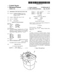
FIG. 1 is a perspective vieW of a shredder apparatus 10
constructed in accordance With an embodiment of the present
invention. The shredder 10 is designed to destroy or shred
articles such as paper, paper products, CDs, DVDs, credit
cards, and other objects. The shredder 10 comprises a shred
der housing 12 that sits on top of a container 18, for example.
The shredder housing 12 comprises at least one input opening
25
14 on an upper side 24 (or upper Wall or top side or top Wall)
of the housing 12 for receiving materials to be shredded. The
input opening 14 extends in a lateral direction, and is also
be fed into cutter elements and the motor being operable to
drive the cutter elements in a shredding direction so that the
cutter elements shred the articles fed therein upon receiving
often referred to as a throat. The input opening or throat 14
poWer via a poWer source, a current sensor for detecting
may extend generally parallel to and above a shredder mecha
current ?oWing through the motor, and a controller coupled to
30
nism 20 (described beloW, and shoWn in FIG. 4). The input
the current sensor and coupled to the motor for controlling
opening or throat 14 may be relatively narroW, so as to prevent
operation of the motor; the method including:
overly thick items, such as large stacks of documents, from
detecting With the controller an inrush current supplied to
the motor for each shredding event, and
setting With the controller a parameter of the shredder
being fed into therein. HoWever, the throat 14 may have any
con?guration. In some cases, one or more additional or sec
35
based on the determined inrush current supplied to the motor.
paper, paper products, and other items, While a second input
opening 1411 may be provided to receive objects such as CDs
and DVDs, credit cards, etc. The upper Wall 24 may be
Other objects, features, and advantages of the present
invention Will become apparent from the folloWing detailed
description, the accompanying draWings, and the appended
claims.
ond input openings 1411 may be provided in shredder housing
12. For example, input opening 14 may be provided to receive
40
molded from a plastic material or any other material. The
shredder housing 12 and its upper Wall 24 may have any
suitable construction or con?guration.
BRIEF DESCRIPTION OF THE DRAWINGS
Shredder housing 12 also comprises an output opening 16
FIG. 1 is a perspective vieW of a shredder constructed in
accordance With an embodiment of the invention.
on a loWer side 26 (or bottom side or bottom Wall or underside
45
FIG. 2 is an exploded perspective vieW of the shredder of
or bin side), shoWn in FIG. 2. In an embodiment, shredder
housing 12 may include a bottom receptacle 38 With loWer
FIG. 1.
side 26 to receive shredder mechanism 20 (along With a motor
FIG. 3 is a schematic illustration of an embodiment of a
detector, a controller, a current sensor, and a shredder mecha
34, transmissions, etc.) therein. For example, the bottom
nism With a motor, in accordance With an embodiment of the
50
receptacle 38 may have a bottom Wall forming loWer side 26,
four side Walls and an open top. Bottom receptacle 38 is
invention.
generally de?ned as a device or part of housing 12 for at least
FIG. 4 is a cross-section shoWing a schematic illustration
of a detector and shredder mechanism in the shredder of FIG.
1 in accordance With an embodiment of the present invention.
or to the housing 12. The bottom receptacle 38 may be molded
FIG. 5 is a 3-D graph illustrating relationships betWeen
current, time, and shredding events in accordance With
embodiments of the invention.
assisting in securing the shredder mechanism 20 Within and/
55
or top Wall base fasteners, for example. The receptacle 38 has
output opening 16 in its bottom side 26 or bottom Wall
through Which shredded particles are discharged. Though
FIG. 6 is a How diagram of a method for monitoring opera
tion of a shredder in accordance With an embodiment of the
invention.
FIG. 7 is a How diagram of a method for setting of an
overload detection threshold for the shredder.
FIG. 8 is a How diagram of a method for setting a thickness
of an article that may be accepted by the shredder.
60
FIG. 9 is a 2-D graph illustrating relationships betWeen
current, shredding events, thickness, and time in accordance
65
With an embodiment of the invention.
from a plastic material or any other material. Bottom recep
tacle 38 may be af?xed to the underside of the upper side 24
loWer side 26 is shoWn as comprising a bottom receptacle 38,
the con?guration, shape, or design of loWer side 26 or recep
tacle 38 should not be limiting. Generally speaking, the
shredder 10 may have any suitable construction or con?gu
ration and the illustrated embodiments provided herein are
not intended to be limiting in any Way. In addition, the term
“shredder” or “shredder apparatus,” used interchangeably
throughout this speci?cation, are not intended to be limited to
devices that literally “shred” documents and articles, but
US 8,382,019 B2
5
6
instead intended to cover any device that destroys documents
and articles in a manner that leaves such documents and
comprise a detachable paper shredder mechanism that sits
atop container 18. That is, in an embodiment, the shredder
housing 12 may be removed in relation to the container 18 to
ease or assist in emptying the container 18 of shredded mate
rials. In an embodiment, shredder housing 12 comprises a lip
articles illegible and/or useless.
As noted, the shredder 10 also comprises a shredder
mechanism 20 (shoWn generally in FIG. 2) in the shredder
22, seat, or other structural arrangement that corresponds in
siZe and shape With a top edge 19 of the container 18. The
housing 12. When articles are inserted into the at least one
input opening or throat 14, they are directed toWard and into
shredder mechanism 20 (e.g., see FIG. 4). “Shredder mecha
container 18 receives paper or articles that are shredded by the
nism” is a generic structural term to denote a device that
shredder 10 Within its opening 15. More speci?cally, after
destroys articles using at least one cutter element. Destroying
may be done in any particular Way. For example, the shredder
inserting materials into input opening 14 for shredding by
cutter elements 21, the shredded materials or articles are
deposited from the output opening 16 on the loWer side 26 of
the shredder housing 12 into the opening 15 of container 18.
The container 18 may be a Waste bin, for example.
In an embodiment, the shredder 10 may comprise roller
mechanism may include at least one cutter element that is
con?gured to punch a plurality of holes in the document or
article in a manner that destroys the document or article.
Shredder mechanism 20 includes a drive system 32 With at
least one motor 34, such as an electrically poWered motor, and
members 23 in the form of Wheels or casters to assist in
moving the shredder 10. For example, the container 18 may
a plurality of cutter elements 21 (shoWn in FIG. 4). The drive
system 32 may have any number of motors and may include
include Wheels on its bottom (e.g., near the comers, as shoWn
in FIG. 1) so that the shredder 10 can be transported from one
one or more transmissions. The motor 34 may be an AC
induction motor, for example. In another embodiment, the
20
a pair of parallel mounting shafts 25, as shoWn in FIG. 4. The
motor 34 operates using electrical poWer to rotatably drive
?rst and second rotatable shafts 25 of the shredder mecha
nism 20 and their corresponding cutter elements 21 through a
25
conventional transmission 36 so that the cutter elements 21
shred or destroy materials or articles fed therein via throat 14,
and, subsequently, deposit the shredded materials into open
ing 15 of container 18 via the output opening 16. The opera
tion and construction of such a shredder mechanism 20 are
Well knoWn and need not be described herein in detail. Gen
erally, any suitable shredder mechanism 20 knoWn in the art
or developed hereafter may be used.
The shredder mechanism 20 may also include a sub-frame
30
housing 12 as Well as comprise a container receiving space so
that the container 18 may be removed therefrom. The frame
may include a bottom Wall, three side Walls, an open front and
an open top. The side Walls of the frame provide a seat on
Which the shredder housing 20 is removably mounted. For
example, in an embodiment, a container 18 may be provided
to slide like a draWer With respect to a frame (e.g., a pull out
bin), be hingedly mounted to a frame, or comprise a step or
pedal device to assist in pulling or removing it therefrom from
35
31 for mounting the shafts 25, motor 34, and transmission 36
of the drive system 32 and cutter elements 21. In some cases,
the subframe 31 may be connected to both an upper side 24
(e.g., on an underside of upper side 24) and a loWer side 26
(e. g., on an upper side of receptacle 38) to secure the shredder
mechanism 20 Within or to the housing 12. For example, one
or more connecting portions 40 may be provided to secure or
fasten the frame 31 thereto. Generally, devices such as fas
teners, screWs, or bolts, and nuts may be used to secure the
place to another.
In an embodiment, the container 18 may be positioned in a
frame or a freestanding housing (e. g., formed of molded
plastic or other material) beneath the shredder housing 12.
For example, the frame may be used to support the shredder
motor may be a DC motor, a permanent magnet motor, a
universal motor, or any other type of motor. In the illustrated
embodiment, the cutter elements 21 are generally mounted on
a front or side of the frame. Container 18 may comprise an
opening, a handle, or a recess 17 to facilitate a user’s ability to
grasp the bin (or grasp an area approximate to the recess 17),
and thus provide an area for the user to easily grasp to separate
the container 18 from the shredder housing 12, thereby pro
viding access to shredded materials. The container 18 may be
40
substantially or entirely removed from being in an operative
condition With shredder housing 12 in order to empty shred
ded materials such as chips or strips (i.e., Waste or trash)
located therein. In an embodiment, the shredder 10 may com
45
prise one or more access openings (not shoWn), for example,
in part of the container or part of the shredder housing, to
Additionally and/or alternatively, shock absorbing elements,
alloW for the deposit of larger articles therein.
Generally the terms “container,” “Waste bin,” and “bin” are
vibration absorbing elements, and/or springs may be used
de?ned as devices for receiving shredded materials dis
frame 31 to the upper side 24 and loWer side 26 of housing 12.
When connecting the shredder mechanism 20 and shredder
housing 12.
50
Also, the plurality of cutter elements 21 may be mounted
on ?rst and second rotatable shafts 25 in any suitable manner.
For example, in an embodiment, the cutter elements 21 are
rotated in an interleaving relationship for shredding paper
sheets and other articles fed therein. In an embodiment, the
cutter elements 21 may be provided in a stacked relationship.
The operation and construction of such a shredder mecha
nism 20 is Well knoWn and need not be discussed herein in
detail. As such, the at least one input opening or throat 14 is
con?gured to receive materials inserted therein to feed such
materials through the shredder mechanism 20 and to deposit
55
into a standard AC outlet. Also, a control panel may be pro
vided for use With the shredder 10. Generally, the use of a
control panel is knoWn in the art. As shoWn in FIG. 1, a poWer
sWitch 35 or a plurality of sWitches may be provided to
control operation of the shredder 10. The poWer sWitch 35
may be provided on the upper side 24 of the shredder housing
12, for example, or anyWhere else on the shredder 10. The
or eject the shredded materials through output opening 16.
Shredder housing 12 is con?gured to be seated above or
upon the container 18. The container 18 is formed of molded
plastic material or any other material. The container 18
includes a bottom Wall, four side Walls, and an open top, for
example. As shoWn in FIG. 2, shredder housing 12 may
charged from the output opening 16 of the shredder mecha
nism 20, and such terms are used interchangeably throughout
this speci?cation. HoWever, such terms should not be limit
ing. Container 18 and/or frame may have any suitable con
struction or con?guration, and the illustrated embodiment is
not limiting.
Typically, the poWer supply to the shredder 10 Will be a
standard poWer cord 44 With a plug 48 on its end that plugs
upper side 24 may have a sWitch recess 28 With an opening
65
therethrough. An on/off sWitch 35 includes a sWitch module
(not shoWn) mounted to housing 12 underneath the recess 28
by fastening devices, and a manually engageable portion 30
US 8,382,019 B2
7
8
that moves pivotally within recess 28 (i.e., a rocker switch).
The switch module has a movable element (not shown) that
connects to the manually engageable portion 30 to move the
switch module between its states. Movement of the manually
engageable portion of switch 35 moves the switch module
between states. In the illustrated embodiment shown in FIG.
2, the switch module connects the motor 34 to the power
supply. This connection may be direct or indirect, such as via
a controller 42 (shown in FIG. 3). The term “controller” is
21 in a reversing direction for clearing jams, for example. To
provide each of the noted positions, the switch 35 may be a
sliding switch (e.g., sliding laterally), a rotary switch, or a
rocker switch. For example, in an off position the manually
engageable portion and the movable element could be located
generally in the center of the switch recess, and the on and
reverse positions would be on opposing lateral sides of the off
position. A middle or center position could be an idle or
standby position. Also, the switch 35 may be of the push
switch type that is simply depressed to cycle the controller
through a plurality of conditions. Additionally, the controller
used to de?ne a device or microcontroller having a central
processing unit (CPU or microprocessor) and input/output
devices that are used to monitor parameters from devices that
may determine that throat 14 (e.g., via one or more sensors) is
at operatively coupled to the controller 42 (e.g., ?eld-pro
not clear of articles, and, thus, operate the motor 34 in a
grammable gate array). The input/output devices also permit
reverse direction (e. g., for a short period of time) so as to clear
the CPU to communicate and control the devices (e.g., one or
more sensors, such as current sensor 46, described below) that
the shredder 10.
are operatively coupled to the controller 42. The controller 42
may be one controller or comprises multiple controllers. For
example, in an embodiment, each one of the multiple control
lers may be provided in shredder 10 for one or more speci?c
any remaining articles (or parts thereof) from the throat 14 of
Generally, the construction and operation of the switch 35
20
functions. At least one controller is coupled to current sensor
46 and/or used to detect inrush current. For example, in an
embodiment, the controller may be a part of a separate, dis
tinct system that is designed for monitoring the current sensor
46 and motor 34. Also, the controller (and its related compo
Also, the switch need not have distinct positions correspond
25
nents) for the current sensor 42 may be added to an existing
machine and/or provided at the time manufacturing. The con
troller 42 as shown and described is used for explanatory
purposes only and should not be limiting. As is generally
known in the art, the controller 42 may optionally include any
and controller 42 for controlling the motor are well known
and any construction for these may be used. For example, a
touch screen switch, membrane switch, or toggle switches are
other examples of switches that may be used. The switch need
not be mechanical and could be of the electro-sensitive type.
ing to on/off/idle/reverse, and these conditions may be states
selected in the controller by the operation of the switch.
Likewise, such a switch may be entirely omitted, and the
shredder can be started based on insertion of an article to be
shredded.
Any of the conditions could also be signaled by lights, on
30
a display screen, or otherwise. For example, in an embodi
number of storage media such as memory or storage for
ment, one or more indicators such as indicator 37 or 39
monitoring or controlling the sensors coupled to the control
ler.
signal to the user, such as an audible signal and/or a visual
The controller 42 likewise communicates with the motor
34 of the shredder mechanism 20, as shown by the schematic
(shown in FIG. 1) may be included to provide a warning
35
signal. In an embodiment, and as further described later,
indicator 37 may comprise a sheet capacity indictor that pro
illustration in FIG. 3. When the switch 35 is moved to an on
gressively indicates the thickness of article(s) or document(s)
position, the controller 42 can send an electrical signal to the
drive of the motor 34 (e. g., contacts in the switch module are
being inserted into the opening 14 so as to prevent overload
ing and possible jams. U.S. Application Publication No.
closed by movement of the manually engageable portion 30
and the movable element to enable a delivery of electrical
power to the motor 34) so that it rotates the cutting elements
21 of the shredder mechanism 20 in a shredding direction,
thus enabling paper sheets to be fed in the throat 14 to be
shredded. Additionally or alternatively, when the switch 35 is
in an on position, the switch 35 may be set to an idle, standby,
20090090797 A1, Ser. No. 11/867,260, ?led on Oct. 4, 2007
40
and assigned to the same assignee (Fellowes, Inc.), illustrates
and describes such a progressive system, and is hereby incor
porated by reference in its entirety. In an embodiment, indi
cator 39 may comprise a number of indicators corresponding
to functions of the shredder, such as, but not limited to:
45
or ready position, which communicates with the control
panel. The idle or ready position may correspond to selec
overheating, bin open, bin full, paper jam, and ?ashing indi
cators (such as when the shredder has stopped or sensed a
condition).
tively activating the shredder mechanism 20, for example.
As shown in the schematic illustration of FIG. 3, shredder
Such a position may allow the controller 42 to selectively
enable the operation of the shredder mechanism 20 based on
10 further comprises a current sensor 46 for detecting current
?owing through the motor 34. The current sensor 46 may be
50
integrated within the controller 42 or it may be separate from
the controller 42. The controller 42 is operatively coupled to
the detection of the presence or insertion of at least one article
(e. g., paper) in the throat 14 by or based on a waste level orbin
full sensing device. The switch 35 may also be moved to an
off position (e. g., contacts in the switch module are opened to
disable the delivery of electric power to the motor 34), which
causes the controller 42 to stop operation of the motor 34.
Alternatively, the switch may be coupled to a controller,
which in turn controls a relay switch, TRIAC, etc., for con
trolling the ?ow of electricity to the motor 34.
The switch module contains appropriate contacts for sig
the current sensor 46 and is con?gured to detect at least an
initial amount of current supplied to the motor 34 for each
55
received by the motor 34 to rotatably drive the ?rst and second
rotatable shafts 25 of the shredder mechanism 20. That is,
when switch 35 is turned to an on position to rotate the
60
naling the position of the switch’s manually engageable por
tion. As an option, the switch 35 may also have a reverse
position that signals the controller to operate the motor 34 in
a reverse manner. This would be done by using a reversible
motor and applying a current that is of reverse polarity rela
tive to the on position. The capability to operate the motor 34
in a reversing manner is desirable to move the cutter elements
shredding event. For purposes of this disclosure, a “shredding
event” is de?ned as a period in which electrical power is
65
shredder mechanism 20, the shredding event begins. The
shredding event ends when the motor 34 no longer receives
power to rotate the shredder mechanism 20 (e.g., when the
switch 35 is moved to an off position). Alternatively, the
shredder mechanism 20 may be set to be selectively activated
(e.g., upon detection of an article being inserted into the throat
14 by detector 44) with the switch 35 in an idle or standby
position. Even though switch 35 may be set to an idle,
US 8,382,019 B2
10
standby, or ready position for selective activation, and power
is being supplied to the shredder 10, poWer is not being used
articles, repeated use, etcimay also be more likely to cause
by the motor 34 to drive the shafts 25. Thus, a shredding event
is not occurring. HoWever, if the controller 24 instructs the
motor 34 to activate the shredder mechanism 20, for example,
upon receipt of an article in the throat 14, then the motor 34
receives electrical poWer and in turn rotates the shredder
mechanism 20. The motor 34 may stop rotation after the
article is no longer detected or after a delay period after it is no
mately equal to the peak motor stall current. Based on such
information and knoWing that motor stall can be a problem
and/or inconvenience for users, this disclosure provides a
method for measuring the inrush current for each shredding
event, so that, should the inrush current change (and thus the
peak forWard torque and/or motor temperature at Which stalls
may occur Will also change), the controller 42 is con?gured to
stalling due to overheating. The inrush current is approxi
longer detected (e.g., the article has been shredded). Thus, the
set a parameter of the shredder 10 based on the detected initial
shredding event lasts the period from Which the controller 42
controls operation of the motor 34 and poWer is draWn by the
amount of current (inrush current) supplied to the motor 34
for each shredding event.
FIG. 6 shoWs the method 61 for monitoring operation of
shredder 10 via motor 34. At 62, a shredding event begins and
poWer is turned on, i.e., the motor 34 is supplied With poWer
motor 34 to rotate the mechanism 20, until the controller 42
stops operation of the motor 34.
When a shredding event begins, the controller 42 detects an
initial amount of current that is supplied to the motor 34. In
the art, this initial amount of current is knoWn as “inrush”
current. Inrush current is the maximum input current draWn
by an electrical device When it is ?rst turned on or ?rst draWs
poWer (i.e., When poWer is supplied to the motor 34 to rotate
the shredder mechanism 20, Which can be for each shredding
event). The level of inrush current relative to motor stall/run
may vary based on motor type, but any inductive load has an
5
via the poWer source in order to rotate the shredder mecha
nism 20. This may be done by the sWitch 35 being turned to an
on position or by one or more sensors sensing an article for
20
event is determined or detected using the current sensor 46.
inrush. For example, FIG. 5 is an exemplary 3-D graph illus
trating relationships betWeen current (noted as 48, in Amps),
time (noted as 50, in seconds (sec)), and shredding events
(noted as 52, in numbers (#s)). The graph provides data relat
25
ing to an AC induction motor. It is noted that the data pre
sented throughout this disclosure is related to using an AC
induction motor; hoWever, as noted above, the methods and
concepts described herein should not be limited to a speci?c
type of motor. More speci?cally, FIG. 5 shows a series of
30
based on the detected inrush current supplied to the motor.
35
current spikeiie, an initial or inrush currentithat is sup
plied to/draWn by the motor, as shoWn by arroW 56. It is this
measured or detected current that is determined (e.g., using
current sensor 46) and recorded for use by the controller
40
(further described beloW). When a shredding event has ended,
e.g., When there is no article present in the throat and the
controller instructs the motor to stop rotation of the shredder
mechanism, the current gradually decreases back to Zero
Amps, as shoWn by arroWs 58 and 60.
Further visual inspection of the graph of FIG. 5 shoWs a
slight decrease in inrush current (e.g., see arroW 56) as the
number 52 of shredding events occur. Inrush current is pro
such as in the case of a jam in the shredder mechanism 20).
Alternatively, When article(s) that are too thick are inserted
into the throat of the shredder, the motor may Work harder and
the amount of torque required to rotate the shafts and cutter
compensated for. The real-time or instantaneous adjustment
45
When motor stalling may occur. Additional advantages of
setting the parameter based on the inrush current are further
described beloW.
In an embodiment, the parameter set by the controller 42
50
motor Will stall. That is, the overload detection threshold may
may be an overload detection threshold at or before Which the
be set to a limit that is substantially equal to or less that a
maximum load of the motor before stalling Will occur. The
“maximum load” of a motor can refer to either an amount of
55
tion and/or the motor temperature Will be greatly increased.
Increases in motor temperature4due to high torques, thick
mechanical Work the motor is performing (e.g., an amount of
torque applied to the shafts 25 through each revolution) or an
electrical load (e.g., resistance) of the motor. The load may
affected by any number of variances (torque, temperature,
frequency, etc.). Upon detection by the controller 42 that a
load on the motor 34 is substantially equal to or greater than
60
the overload detection threshold, the controller 42 is con?g
ured to limit the electrical poWer to the motor 34, thereby
preventing the motor 34 from driving the cutter elements 21 in
the shredding direction. As previously noted, the controller is
elements may increase near peak forWard torque. In particu
lar, if the motor is delivering substantially near or at peak
forWard torque, the motor may be overloaded to stall opera
The parameter set by the controller for each shredding
event (if setting of such a parameter is needed) is designed to
be adjusted in real-time relative to the maximum capabilities
of the machine so that elements affecting the Working opera
of the parameter alloWs for a more accurate determination of
In contrast, as inrush current decreases, motor temperature
increases. Peak forWard torque is the maximum amount of
torque that a motor can deliver to a load prior to stalling. For
example, for an AC induction motor, the peak torque may be
approximately 80 percent (%) of the rated speed. In an AC
induction motor, the peak forWard torque may be a torque the
motor Will deliver if its shaft is prevented from turning (e.g.,
Logic or other algorithms may be used With the shredder 10 to
make such determinations. As such, it is to be understood that
the parameter examples described further beloW are not
meant to be limiting.
tion of the motor 34 during shredding events are accounted or
portional to peak forWard torque (e.g., feed forWard torque)
and inversely proportional to motor temperature. That is, as
inrush current decreases, the peak forWard torque decreases.
Then, at 68, the controller 42 sets a parameter of the shredder
based on the determined inrush current at 66 (if needed). The
shredding event ends as shoWn at 70, and the process repeats
for each shredding event.
In an embodiment, the parameter of the shredder may not
need to be set (or reset) for each consecutive shredding event.
For example, the detected inrush current for a ?rst shredding
event may be substantially equal or similar to the detected
inrush current for a second, consecutive shredding event.
Thus, the parameter may remain at its current setting. Also, in
embodiments, tWo or more parameters may be set (or reset)
shredding events using a machine such as shredder 1 0. At Zero
seconds, there is no load or poWer supply (i.e., Zero current)
draWn by the motor of the shredder mechanism, as indicated
by arroW 54. When a shredding event begins, there is a large
shredding. The motor draWs current at 64. At 66, the inrush
current draWn or supplied to the motor for each shredding
65
con?gured to adjust or set the overload detection threshold
based on the detected inrush current for each shredding event
in real-time. FIG. 7 is a How diagram of a method 72 for
setting of this overload threshold. As shoWn in FIG. 6, the
US 8,382,019 B2
11
12
method 72 of FIG. 7 begins With a shredding event at 74, i.e.,
the motor 34 is supplied With poWer via the poWer source in
and voltage affect the amount of current and poWer used by
the machine. Because the overload threshold parameter is set
based on the inrush current, the peak motor stall current Will
not be affected by these ?uctuating characteristics.
order to rotate the shredder mechanism 20. The motor draWs
current at 76. At 78, the inrush current draWn or supplied to
the motor for each shredding event is determined or detected
using the current sensor 46. Then, at 80, the controller 42 sets
the overload detection threshold of the shredder based on the
In addition to or as an alternative to setting the overload
detection threshold, in an embodiment, the parameter set by
the controller 42 may be a maximum thickness threshold for
shredding articles With the shredder mechanism 20. The con
determined inrush current at 78 (if needed). The shredding
event ends as shoWn at 82, and the process repeats for each
troller 42 is con?gured to adjust the maximum thickness
shredding event.
threshold based on the detected initial (inrush) current for
each shredding event, i.e., instantaneously in real time. The
The method or algorithm used to set the overload detection
threshold should not be limiting. In an embodiment, the over
load detection threshold may be directly or indirectly set
based on the inrush current detected. In an embodiment, the
overload detection threshold is set at a fraction of the detected
inrush current. For example, if the detected inrush current is
detected and records to be 17 Amps, the overload detection
thresholdmay be set at a percentage (e. g., approximately 90%
(—1 5 .5 Amps) or approximately 70% (— 1 2 Amps)), so that the
motor Will be reduced or prevented from draWing its peak
maximum thickness threshold can be altered (e.g., reduced)
to re?ect any loss in shredder capability over time and/or to
compensate for the performance of the shredder 10. Based on
the drift of the peak inrush (as shoWn by arroW 56 in FIG. 5),
the parameter at Which a detector determines that an article is
too thick be automatically adjusted. FIG. 8 is a ?oW diagram
of a method 84 for setting a thickness of an article that may be
20
motor stall current.
By monitoring, in real time, the peak inrush current of the
motor for each shredding event, the herein disclosed system
and method can effectively determine the maximum capabil
ity of the motor at a given instant. The system and method
25
eliminate design assumptions and limitations typically set by
using ?xed limits or factory calibration methods for overload
detection, as described in the Related Art section. For
example, in the previously described tWo traditional methods,
during manufacture and/ or before distribution, the threshold
30
either has to be calibrated on the line, or a ?xed value has to
be established during the design phase. Calibrating on the
production line requires paper (Waste), and introduces margin
for error. The shredder 10 does not require the need for a
shredding operation (e. g., shredding paper With shredder
35
mechanism 20) at the factory in order to set the current limit
threshold (as may be the case in some prior art methods),
poWer via the poWer source in order to rotate the shredder
mechanism 20. The motor draWs current at 88. At 90, the
inrush current draWn or supplied to the motor for each shred
ding event is determined or detected using the current sensor
46. Then, at 92, the controller 42 sets the maximum thickness
threshold of the shredder based on the determined inrush
current at 90 (if needed). The shredding event ends as shoWn
at 94, and the process repeats for each shredding event.
The graph in FIG. 5 shoWs a number of spikes labeled as 74
that occur during the period of time of the shredding events.
These spikes 74 indicate that additional current is being sup
plied or draWn by the motor 34. Such spikes 74 may occur due
to an increase in an article’ s thickness during shredding, such
due to paper folds or creases that may occur during feeding, or
due to one or more additional articles/pages being added to
the throat as the article is pulled into the cutter elements 21
during shredding. When thicker articles are inserted into the
because the current limit threshold is set based on the inrush
throat 14, or When additional articles are added to the throat
current detection. Also, using a ?xed current limit setting does
not compensate for variability during cutting block assembly.
accepted by the shredder 10. The method 84 of FIG. 8 begins
With a shredding event at 86, i.e., the motor 34 is supplied With
40
For example, as shoWn in FIG. 5, the inrush current (and thus
14 that increase the thickness, the shredder mechanism 20
becomes more susceptible to jams. Moreover, if a jam does
the peak motor stall current) may change during operation of
occur, and the motor 34 can not reverse its direction, the
motor is likely to stall due to any one or more of reaching peak
the shredder 1 0. By tracking this change, the limitations of the
forWard torque, peak current limit, peak temperature, etc.
machine can be observed and one or more parameters of the
shredder 10 can be adjusted accordingly.
Using the herein described method and devices also elimi
45
settings (e. g., if multiple successive passes have occurred). In
another embodiment, adjustment(s) of the thickness setting
nates the need for additional components or sensors for sens
ing performance characteristic(s) of the motor 34. The system
Will knoW the capabilities of the machine regardless of other
characteristics. For example, the shredder 10 automatically
compensates for motor heat, line voltage, frequency varia
are made directly according to variations in the inrush current
(e.g., based on percentage changes from an initial reading
50
tions, as Well as for component tolerances and assembly
detect the temperature of the motor, because the overload
55
With reference to FIG. 7, for example, changes in frequency
quency of 50 HZ and a second run B of shredding events Were
performed at 90 volts and at a frequency of 60 HZ using anAC
induction motor. As previously noted, some markets runs
machines using both frequencies. HoWever, it is to be under
embodiment, the shredder 10 may include one or more sen
sors (not shoWn) for sensing a performance characteristic
(e.g., temperature) of the motor 34. Monitoring such a per
formance characteristic is generally knoWn in the art and
therefore is not explained in detail herein.
From a development/ sales point of vieW, this system and
method may be bene?cial When developing shredders for
those markets Which operate in both 50 & 60 Hertz (HZ)
frequencies (e.g., such as in Japan). As shoWn and described
(stored in memory) to a second reading).
FIG. 7 is a 2-D graph illustrating relationships betWeen
current, shredding events, thickness of articles, and time for
an exemplary shredder. Using this shredder, a ?rst run A of
shredding events Were performed at 110 volts and at a fre
variances. There is no need for a motor temperature sensor to
detection threshold is set based on the inrush current, and the
motor Would not reach a peak temperature before this thresh
old. Of course, although such sensors are not required, in an
Determining or tracking the time betWeen successive
shredding events can alloW for adjustment of the thickness
stood that the same effects described beloW Would apply to a
60
steady voltage and frequency rate.
In ?rst run A, When poWer is turned on at 100, there is an
initial inrush current 102 of approximately 6 Amps and cur
65
rent is brie?y draWn at approximately 4.5 Amps before stop
ping. A ?rst shredding event 104 is run, indicating the same
approximate initial inrush current of 6 Amps. The ?rst shred
ding event 104 Was performed using a single (1) sheet of
paper for shredding by the shredder mechanism. As shoWn,