1
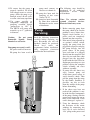
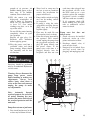
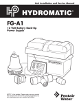
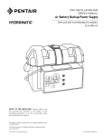
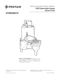
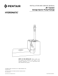
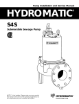
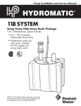
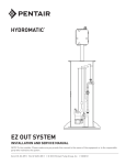
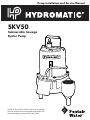
Pump Installation and Service Manual
SKV50
Submersible Sewage
Ejector Pump
NOTE! To the installer: Please make sure you provide
this manual to the owner of the pumping equipment or to
the responsible party who maintains the system.
General
Information
Thank you for purchasing your
Hydromatic® pump. To help
ensure years of trouble-free
operation, please read the
following manual carefully.
Before Operation:
Read the following instructions
carefully. Reasonable care and
safe methods should be practiced.
Check
local
codes
and
requirements before installation.
Attention:
This manual contains important
information for the safe use of
this product. Read this manual
completely before using this
product and refer to it often for
continued safe product use.
DO NOT THROW AWAY OR
LOSE THIS MANUAL. Keep it
in a safe place so that you may
refer to it often.
WARNING: Before handling
these pumps and controls,
always disconnect the power
first. Do not smoke or use
sparkable electrical devices or
flames in a septic (gaseous) or
possible septic sump.
Pump
Warning
To reduce risk of electrical shock:
1. Risk of Electrical Shock:
This pump has not been
investigated for use in
swimming pool areas.
2
2. Risk of Electrical Shock:
Connect only to a properly
grounded receptacle.
Septic tank to be vented
in accordance with local
plumbing codes.
Do not smoke or use sparkable
electrical devices or flame in a
septic (gaseous) or possible
septic sump.
If a septic sump condition may
exist and if entry into sump is
necessary, then (1) provide
proper safety precautions per
OSHA requirements and (2)
do not enter sump until
these precautions are strictly
adhered to.
Do not install pump in location
classified as hazardous per
N.E.C., ANSI/NFPA 70 - 1999.
Failure to heed above cautions
could result in injury or death.
Pump
Installation
These important instructions must
be followed for satisfactory
performance of your pump. Before
installation, check your local
electrical and plumbing codes.
1. Provide
proper
sump.
Recommended
minimum
sump diameter is 18".
2. Make sure the wide-angle
float switch (excluding those
automatic models equipped
with a diaphragm pressure
switch) hangs freely. The float
should not come in contact
with the side or bottom of the
sump pit.
3. Make sure sump is free of
string, cloth, nails, gravel, etc.
before installing pump.
4. Do not set pump directly on
the bottom of sump pit if it is
not solid. Raise the pump by
placing bricks or concrete
blocks underneath it.
5. Use steel or plastic pipe for all
connecting lines between
pump and sewer outlet.
Note: Some city regulations
do not allow installing a
pump with plastic pipe. Check
local regulations.
6. In applications where the
pump may sit idle for months
at a time, it is recommended
that the pump(s) be cycled
every month to ensure the
pumping system is working
properly when needed.
7. Hydromatic check valve
should be installed in discharge
pipe. Install check valve with
arrow on valve body pointing
in the direction of the flow.
8. A shutoff valve should also
be used.
9. An audible alarm system, such
as the Q Alert, for high water
conditions should be installed
in every pump pit for greater
protection.
Note: The Q Alert is for
indoor use only. For outdoor
applications contact your
Hydromatic distributor.
10.Connect to power source
using 3-prong grounded AC
receptacle. Do not remove
ground pin from electrical
plug. Do not use an extension
cord or adaptor plug.
11. For proper automatic operation,
make sure the pump power
cord is plugged into the back
of the piggyback receptacle on
the wide angle float switch.
12.To ensure that the pump is
properly installed, fill basin
with enough water to activate
pump. Allow the pump to go
through several on-off cycles
to assure satisfactory operation.
13.Use pump partially or
completely submerged for
pumping waterlike liquids
(temperature to 140° F).
The SKV50 will pump solid
materials up to 2" (spherical)
in diameter.
Caution:
Do not pump
flammable liquids, strong
chemicals or salt water.
Your pump warranty is void...
If... power cord has been cut.
If... pump has been used to
pump mud, cement, tar,
abrasives or chemicals.
If... pump has been used for
pumping of hot water
(above 120° F).
If... pump has been dismantled
by other than authorized
Hydromatic service center
or distributor.
Pump
Servicing
Read the following instructions
carefully before replacing any
parts. Reasonable care and safe
methods should be practiced.
Check
local
codes
and
requirements before installation.
Only competent electrician
should make the installations.
The following steps should be
performed by an authorized
Hydromatic
service
center
or distributor.
Note: Use extreme caution
around electrical devices.
Electrical shock may occur.
1. Before removing pump from
the sump, check to be sure the
problem is not a blown fuse,
tripped circuit breaker or a
power cord not completely
inserted into the receptacle.
2. If the unit is being operated by
an optional control switch,
unplug the pump from the
piggyback receptacle and plug
the pump directly into the
power source. If the pump
starts each time it is plugged
directly into the receptacle and
does not start each time when
plugged into the piggyback
switch with the float raised or
diaphragm pressed up to a start
position, replace the complete
switch assembly and retest
with new assembly.
3. If pump fails the above two
steps, remove pump and
switch from power source to
avoid electrical shock. Then
pull the pump from the sump
by the handle. Sandblast, if
possible, any dirt or trash
from the outside of the pump
before dismantling.
4. If the above tests have not
resolved the problem, it may
be in the electrical components
of the pump. Starting with the
power cord, inspect for cuts or
nicks in the insulation. If the
cord is damaged – replace it!
5. Using the ohmmeter, check
the resistance of the motor
windings by connecting one
lead clip to each electrical
“flat” prong on the power cord
3
Pump
Servicing
plug. The ohmmeter should be
on R X 1 setting. Normal
readings are 1.4 to 1.54 ohms
for 115V, 4.5 to 4.9 for 230V.
To check the ground, place the
ohmmeter on R X 100k,
connect one lead clip to the
“ground” prong on the power
cord and touch the other lead
clip to each “flat” prong
individually. If the reading is
other than infinity (∞ on the
ohmmeter scale), a leakage
through stator insulation or
moisture in the windings is
occurring and the stator must
be removed, dried out and
rechecked. A reading at zero
indicates a dead short and the
stator will have to be replaced.
6. To check to see if water has
entered the motor cap, remove
the pipe plug (14) at the top of
the pump and drain the oil into
a bucket. A milky appearance
to the oil indicates that
water has entered through
either worn or damaged seals
or O-rings and replacement
is necessary.
7. Remove the four hex-head
screws (7) from the motor
housing and lift off the motor
housing (4) very carefully as a
grounding wire is attached to
the inside of the motor housing
(4). Remove the ground screw
(13) and set the motor housing
(4) aside.
8. To remove impeller, hold the
rotor shaft assembly with
screwdriver (screwdriver slot
in shaft). Carefully tap impeller
off shaft with a plastic or
rubber hammer. Tap impeller
(11) counterclockwise to
remove. Loctite #277 is
4
applied to shaft at assembly, so
to remove impeller it will be
necessary to break this seal.
This is why the plastic or
rubber hammer is used to
avoid damage to the impeller.
9. Insert a screwdriver under the
edge of the ceramic seal (6)
and lift it off.
10.Remove the stationary half of
the seal (6) by tapping it out
lightly from the top of the seal
plate and then clean the area
with a cloth.
11. Remove the four bolts (16)
holding the motor (12) onto
the seal plate (10) and tap the
shaft and rotor assembly out
with a plastic or rawhide
hammer. The lower ball
bearing will come out with the
shaft and rotor assembly. If
the bearing is rusted or feels
rough when turned, it should
be replaced as in Step 13.
12.Coat the replacement seal (6)
with a thin oil (dielectric,
same as in motor housing)
coating and use a plastic
pusher to install the seal (6)
into the seal plate (10). Do not
use any sharp instruments that
may damage the seal. Do not
chip, scratch or mar the carbon
face.
13.If ball bearing replacement is
necessary as determined in
Step 11, press the bearing on
the shaft, pushing only on the
inner face. If a press is not
available, the bearing can be
tapped on using a sleeve that
bears only on the inner face.
Pressing on the outer face will
result in flat spots on the bearing
and cause early failure.
14.Push the new rotor shaft and
ball bearing assembly into
the seal plate. (Note that the
replacement rotor must be of
the same manufacture as the
existing stator, or vice versa.)
Reassemble the stator (12) to
the seal plate (10) with the four
long cap screws (16). Be sure
to tighten down the bolts
evenly and firmly to prevent
cocking of the stator. An
uneven assembly can cause the
rotor to rub the motor causing
the motor to short.
15.Press the new ceramic seal (6)
in place with the rubber
ring facing the impeller.
This should have a thin oil
(dielectric, same as in motor
housing) coating.
Note: Ceramic must be kept
clean. Any dirt will cause
seal failure.
16.Start the impeller on the shaft
one to two turns; then add a
drop of Loctite #277 to the
impeller threads and screw
the impeller hand tight. The
impeller will force the ceramic
seal into position. The shaft
should be free of dirt, grease,
etc., or the Loctite will not
hold as designed.
Note: Loctite overrun onto the
seal or bearing will result in
shaft seizure.
17.Remove the old seal ring (8)
and stretch on new ring with
O-ring lube.
Do not roll the ring onto seal
plate or water leakage into the
motor housing will result.
18.Fasten the ground wire inside
the motor housing and tuck
wires up into the housing to
prevent rubbing on the rotor;
then assemble housing (4) to
volute (9) with bolts (7).
19.Check for seal leaks by
pressurizing the pump to 7 to 9
pounds of air pressure. Air
bubbles should appear at first,
then stop. If air bubbles
continue, then recheck seals.
20.Fill the motor cap with
high-grade transformer oil
such as Sohio (6) Factopure
SE40 Oil (or equivalent) to
at least 1⁄4" over motor
windings top plate, or to the
top of the stator.
Do not fill the motor housing
completely. Allow air space
for expansion.
Replace oil pipe plug (14).
Recheck with ohmmeter
before applying power.
21.Plug the power cord into a
grounded outlet and check
pump running. Motor should
run smoothly and be free
of vibration.
each time when plugged into
the piggyback switch with
the float raised up to a start
position, replace the complete
piggyback switch assembly
and retest with new assembly.
7. If all symptoms check OK,
motor winding may be open;
take to authorized service
center for check.
2. Water level in sump may be
too low to activate automatic
switch. See installation for
proper on/off levels.
3. Pump and/or switch cord plug
may not be making contact
in receptacle.
4. If pump is using the series
(piggyback) cord plug, the two
plugs may not be plugged
together tightly.
5. Float may be stuck. Be sure
float operates freely in basin.
6. If the unit is being operated by
the optional float control
switch, unplug the pump from
the piggyback receptacle and
plug the pump directly into
the power source. If the
pump starts each time it is
plugged directly into the
receptacle and does not start
Pump
Troubleshooting
1
14
3
Pump runs but does not
deliver water.
1. Check valve may be installed
backward. Arrow on valve
points in direction of flow.
2. Discharge shutoff valve, if
used, may be closed.
3. Pump may be air locked. Start
and stop several times by
plugging and unplugging cord.
2
Servicing should be performed
only by an authorized Hydromatic
service center.
15
19
20
Warning: Always disconnect the
pump from power source
before handling or making any
adjustments. Always wear
rubber boots when there is
water on the floor and you must
unplug the pump or make
any adjustments.
18
17
4
12
21
7
8
Note:
Automatic
thermal
overload protects the sealed-inoil motor. Running dry may
overheat the motor and activate
the overload protector until the
unit cools.
9
6
11
10
Pump does not run or just hums.
1. Line circuit breaker may be off,
or fuse may be blown or loose.
5
NOTE: In sumps where the
pump is operating daily, air
locking rarely occurs.
4. Pump head may be too high.
Pump cannot deliver water
over
24'
vertical
lift.
Horizontal distance does not
affect pumping, except for
friction loss through the pipe.
5. Inlet in pump base may be
clogged. Remove pump and
clean out openings.
6. Impeller or volute openings
may be plugged or partially
plugged. Remove pump and
clean out.
Pump runs and pumps out
sump but does not stop.
1. Float is stuck in up position.
Be sure float is not hung up
and operates freely in basin.
6
Pump runs but delivers only
small amount of water.
1. Pump may be air locked. Start
and stop several times by
plugging and unplugging cord.
Check vent hole in pump case
for plugging.
2. Pump head may be too
high. Pump cannot deliver
water over 24' vertical lift.
Horizontal distance does
not affect pumping, except
loss due to friction through
discharge pipe.
3. Inlet in pump base may be
clogged. Remove pump and
clean out openings.
4. Impeller or volute openings
may be plugged or partially
plugged. Remove pump and
clean out.
5. Pump impeller may be partially
clogged causing motor to
run slow, resulting in motor
overload. Clear impeller.
Fuse blows or circuit breaker
trips when pump starts.
1. Inlet in pump base may be
clogged. Remove pump and
clean out openings.
2. Impeller or volute openings
may be plugged or partially
plugged. Remove pump and
clean out.
3. Pump impeller may be partially
clogged causing motor to
run slow, resulting in motor
overload. Clear impeller.
4. Fuse size or circuit breaker is
too small.
5. Defective motor stator: return
to authorized Hydromatic
service center for verification.
Motor runs for short time
then stops. Then after short
period starts again. Indicates
tripping overload caused by
symptom shown.
1. Inlet in pump base may be
clogged. Remove pump and
clean out openings.
2. Impeller or volute openings
may be plugged or partially
plugged. Remove pump and
clean out.
3. Pump impeller may be partially
clogged causing motor to
run slow, resulting in motor
overload. Clear impeller.
4. Defective motor stator: return
to authorized Hydromatic
service center.
SKV50 PERFORMANCE CURVE
12
40
9
30
6
3
HEAD-FEET
Check vent hole in pump case
for plugging.
Hydromatic pumps have a
small air vent hole in the
impeller cavity to let out
trapped air.
If this hole
becomes plugged, pump may
air lock. To break the air lock,
use a small screwdriver to
clear hole in the impeller
cavity.
As a secondary precaution in
installations of this type —
1/16" hole should be drilled in
the discharge pipe below the
check valve. The check valve
should be 12 to 18 inches
above pump discharge. Do not
put check valve directly into
pump discharge opening.
2. Switch contacts may be stuck;
replace switch.
HEAD-METERS
Pump
Troubleshooting
20
1/2 HP
10
0
0
Capacity-U.S. G.P.M. 0
30
Liters/Second 0
2
60
4
90
150
120
6
8
180
10
SKV50
Parts List
1
14
3
2
15
19
20
18
17
4
12
21
7
8
9
6
Refer to an authorized
Hydromatic service
center to order parts.
Ref. No.
Part No.
1
2
3
4
6
7
8
9
10
11
12
12
14
15
60-000-5
4580-001-1
13425-069-1
56-036-2
14525A010
19100A012
77-003-1
6818-100-2
6846-003-1
8498-006-1
13559-000-1
13593-000-1
14981-001-1
14623-010-1
11
Description
Handle
Drive Screw
Nameplate
Motor Housing
Seal Assy.
Capscrew
Seal Ring
Volute
Seal Plate
Impeller
Stator & Shell 115V Motor
Stator & Shell 230V Motor
Pipe Plug
Cord Assy. *16-3, 10', 115V
10
Qty.
Ref. No.
1
2
1
1
1
4
1
1
1
1
1
1
1
1
15
15
15
17
18
19
20
21
14623-020-1
14623-210-1
14623-220-1
6000-053-1
6000-061-1
75-005-1
139-014-1
13666-000-1
Cord Assy. *16-3, 20', 115V
Cord Assy. *16-3, 10', 230V
Cord Assy. *16-3, 20', 230V
Wire with Terminal
Wire with Terminals
Cord Nut
Cord Grommet
Ground Strap
1
1
1
1
2
1
1
1
Not
Shown
13967-011-5
13967-021-5
14974-008-5
FOR AUTOMATIC OPERATION
Piggyback Switch, 115V-10' Cord
Piggyback Switch, 115V-20' Cord
D-Switch, 115V-10' Cord
1
1
1
Part No.
Description
Qty.
7
LIMITED WARRANTY
HYDROMATIC warrants to the original consumer purchaser (“Purchaser” or “You”) of HYDROMATIC Sump
Pumps, Effluent Pumps, Sewage Pumps (other than 2-1/2"), and Package Systems, that they will be free from
defects in material and workmanship for the Warranty Period of 36 months from date of manufacture.
Our warranty will not apply to any product that, in our sole judgement, has been subject to negligence,
misapplication, improper installation, or improper maintenance. Without limiting the foregoing, operating a
three phase motor with single phase power through a phase converter will void the warranty. Note also that
three phase motors must be protected by three-leg, ambient compensated, extra-quick trip overload relays of
the recommended size or the warranty is void.
Your only remedy, and HYDROMATIC’s only duty, is that HYDROMATIC repair or replace defective products
(at HYDROMATIC’s choice). You must pay all labor and shipping charges associated with this warranty and
must request warranty service through the installing dealer as soon as a problem is discovered. No request
for service will be accepted if received after the Warranty Period has expired. This warranty is not transferable.
EXCEPTIONS: Hydromatic Special Application Pumps, Battery Back-Up Sump Pumps, Filtered Effluent
Pumps, Grinder Pumps, and 2-1/2" Sewage Pumps are warranted for a period of 12 months from date of
purchase or 18 months from date of manufacture, whichever comes first.
HYDROMATIC SHALL NOT BE LIABLE FOR ANY CONSEQUENTIAL, INCIDENTAL, OR CONTINGENT
DAMAGES WHATSOEVER.
THE FOREGOING WARRANTIES ARE EXCLUSIVE AND IN LIEU OF ALL OTHER EXPRESS AND
IMPLIED WARRANTIES, INCLUDING BUT NOT LIMITED TO THE IMPLIED WARRANTIES OF
MERCHANTABILITY AND FITNESS FOR A PARTICULAR PURPOSE. THE FOREGOING WARRANTIES
SHALL NOT EXTEND BEYOND THE DURATION EXPRESSLY PROVIDED HEREIN.
Some states do not allow the exclusion or limitation of incidental or consequential damages or limitations on
the duration of an implied warranty, so the above limitations or exclusions may not apply to You. This warranty
gives You specific legal rights and You may also have other rights which vary from state to state.
This warranty supersedes and replaces all previous warranty publications.
HYDROMATIC
740 East 9th Street, Ashland, OH 44805
Phone: 888-957-8677 • Fax: 888-840-7867 • Web Site: http://www.hydromatic.com
– Your Authorized Local Distributor –
USA
740 East 9th Street, Ashland, Ohio 44805
Tel: 888-957-8677 Fax: 888-840-7867
www.hydromatic.com
© 2007 Hydromatic Ashland, Ohio. All Rights Reserved.
®
CANADA
269 Trillium Drive, Kitchener, Ontario, Canada N2G 4W5
Tel: 519-896-2163 Fax: 519-896-6337
Part # 5625-364-1
Item # W-03-364 Rev. 9/22/09