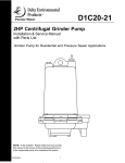
1
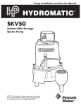
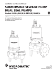
MBM(X)20* SERIES 1150 AND 1750 RPM MODELS *For use in Hazardous Locations Class I, Division 1, Groups C & D SUBMERSIBLE BASIN MIXER INSTALLATION AND SERVICE MANUAL NOTE! To the installer: Please make sure you provide this manual to the owner of the equipment or to the responsible party who maintains the system. Part # 23833A688 | © 2015 Pentair Ltd. | 07/14/15 SAFETY WARNINGS This manual contains important information for the safe use of this product. Read this manual completely before using this product and refer to it often for continued safe product use. WARNING: Severe injury may result from contact with moving propeller. Keep clothing, hands, and feet away from propeller any time power is connected to the mixer. MIXERS Mixers build up heat and pressure during operation. Allow time for mixer to cool before handling or servicing. Failure to heed these warnings and follow the instructions in this manual may result in severe bodily injury or death, or substantial property damage. Only qualified personnel should install, operate or repair mixer. Do not throw away or lose this manual. Keep it in a safe place so that you may refer to it often. This mixer must not be used to mix flammable, combustible or hazardous liquids. Do not wear loose clothing that can become entangled in the propeller or other moving parts. Make sure lifting handles are securely fastened each time before lifting. This mixer is designed to handle materials that could cause illness or disease through direct exposure. Wear adequate protective clothing when working on the mixer. Do not lift mixer by power cord. Do not exceed manufacturer’s recommendation for maximum performance, as this could cause the motor to overheat. To reduce risk of electrical shock, mixer must be properly grounded in accordance with the National Electrical Code and all applicable state and local codes and ordinances. Always secure the mixer in its operating position so it cannot tip over, fall or slide. Always disconnect the mixer from power source before handling or servicing. Do not use in swimming pools, decorative fountains or any installation where human contact with mixer fluid is common. Any wiring to be done on mixers should be done by a qualified electrician. Do not operate mixer without safety devices in place. Never operate a mixer with a power cord that has frayed or brittle insulation. IMPORTANT! Myers® is not responsible for losses, injury or death resulting from a failure to observe these safety precautions, misuse or abuse of mixers or equipment. Never let cords or plug lie in water. Never handle connected power cords with wet hands. WARNING: Risk of electrical shock! Follow all local electrical and safety codes and ordinances as well as the most recent National Electric Code (NEC-ANSI/NFPA 70). All mixers have a ground wire that is connected to a screw in the metal motor housing. This wire goes to the receptacle or control box which must be connected to a good outside ground such as a metal water pipe or ground stake driven at least 8 feet into the ground. CALIFORNIA PROPOSITION 65 WARNING: This product and related accessories contain chemicals known to the State of California to cause cancer, birth defects or other reproductive harm. 2 MBM(X)20 32 31 21 14 12 26 11 19 13 23 36 24 7 18 17 6 1 33 20 11 29 28 35 SECTION A-A 38 34 27 25 23 16 37 9 5 13 A 8 15 B 30 B MBM(X)20 PARTS LIST FOR USE WITH REGAL BELOIT MOTORS Item 1 2 3 4 5 6 7 8 9 10 11 12 13 14 15 16 17 18 19 20 21 22 23 24 25 26 27 Description CORD CAP SCREW – DRIVE #6 SCREW – SET 5/16-18 PLUG – PIPE 1/4 SCREW – MACHINE 10-24 x 3/8 O-RING O-RING O-RING WASHER – LOCK SCREW – MACHINE 5/16-18 x 1 RING – RETAINING CONNECTOR – BUTT 22-16 SCREW – HHC 5/16-18 x 1-1/4 SCREW – CAP 5/16 x 7/8 SCREW – CAP 3/8-16 x 1-1/4 WASHER – SPRING CAP – UPPER BEARING CAP – UPPER BEARING (MBM20 ONLY) HOUSING – MOTOR HOUSING – MOTOR (MBM20 ONLY) HOUSING – UPPER SEAL HOUSING – UPPER SEAL (MBM20 ONLY) PLUG – SPECIAL 1/2 HEX HOUSING – LOWER SEAL HOUSING – LOWER SEAL (MBM20 ONLY) BRACKET – MIXER SEAL – 7/8" BEARING – BALL BEARING – BALL ELECTRODE – WITH RESISTOR ELECTRODE (MBM20 ONLY) SCREW – HHC 5/16-18 UNC x 1-3/4 TUBE – PLASTIC (NOT SHOWN) FERRULE – RUBBER .312 O.D. x .265 I.D. (NOT SHOWN) Eng. No. 22407C607 045800011 05013A027 05022A092 05434A043 05876A122 05876A123 05876A125 06107A015 07597A017 12558A006 12672A002 19100A012 001780011 001010101 19331A005 21570B100X 21570B100 21571D100X 21571D100 21574D100X 21574D100 21577A000 21578C100X 21578C100 526033065 21576A010 08565A013 08565A018 22578A003 22578A004A 001010111 10649A102 Qty. 1 8 2 2 1 1 1 2 1 2 2 2 6 6 2 2 1 1 1 1 1 1 1 1 1 1 2 1 1 1 1 2 2 22579A000 1 22 2 A 10 4 3 SECTION B-B MBM(X)20 MOTOR PARTS LIST Item 36 37 38 Description ROTOR/SHAFT STATOR CONNECTOR 1750 RPM 152260111 152260031 12672A001 (3) 1150 RPM 152270111 152270031 12672A001 (3) MBM(X)20 WET END PARTS LIST Item 28 29 30 31 32 33 34 35 3 Description SCREW – CAP 5/16-18 WASHER – PROPELLER KEY 3/16 SQ. x .69 HOUSING – LIP SEAL LIP SEAL PROPELLER RING – PROPELLER SPACER – PROPELLER Eng. No. 001780041 005190001 101020011 134894002 152220001 152120002 27755A000 27799A000 Never enter a sump chamber after sewage or effluent has been in basin. Sewage water can give off methane, hydrogen sulfide and other gases that are highly poisonous. For this reason, Myers recommends installing the MBM(X) mixer with a quick removal system. See installation drawings for suggested installation. and waste management facilities. The mixers are available in two speeds – 1150 and 1750 rpm. The integral stainless steel motor shaft is sealed by two mechanical seals with an oil chamber between the seals to provide lubrication for both seal faces. Two ball bearings are used to handle the loads. The upper bearing takes radial load, while the larger lower bearing handles both thrust and radial loads. Both bearings are permanently lubricated by the dielectric oil in the motor housing. The motor is fixed within the motor housing and is completely submerged in the dielectric oil for maximum heat transfer. The motor housing and seal chamber are completely sealed with O-rings located at mating part faces. HAZARDOUS LOCATION SERVICE These pumps are to be used for handling sewage, wastewater and storm water only. Do not use in other hazardous locations. These motors must be repaired and serviced only at authorized agency approved service centers or at the Myers factory. Any unauthorized field repair voids the warranty, the hazardous location rating, and agency approval. MOTOR TYPE Motors are Regal Beloit/Marathon™ 3/4 partial, 48 frame 2 hp three-phase, 50 or 60 hertz, 1150 or 1750 rpm with class B insulation. The threephase pump motors require a magnetic starter with 3-leg overload protection. All motors have upper and lower ball bearings and all are oil-cooled and lubricated. SPECIAL INSTRUCTIONS FOR THREEPHASE MIXERS Do not remove cord and strain relief. Do not connect conduit to mixer. Three-phase mixers are always installed with control boxes having magnetic starters with overload protections. Do not try to run three-phase mixers directly across the line. INSTALLATION Warning: Basin or tank must be vented in accordance with local plumbing codes. To connect mixer, run wire from pump to bottom of control box or appropriate junction box suitable for enclosing splice connections. A hole must be cut into the control box for the wires. With power on control box off, connect green (ground) line to ground lug. Connect black (power) wires to power lead terminals. TROUBLESHOOTING Below is a list of troubles and their probable causes: Insufficient mixing 1. Mixer orientation needs adjusted 2. Wrong rotation 3. Speed is too slow NOTE: For a typical CE style control box and not in a position to be pinched or shorted when door is closed. Before installing mixers check rotation of propeller to make sure mixer is connected correctly to magnetic starter. All mixer propellers either single or three-phase must turn counterclockwise when looking from propeller side. To check for proper rotation, lay mixer on side, using Hand position of H-O-A switch. Turn on and off fast so that coast of propeller can be seen. Never put hands or fingers on the propeller when power is connected. Interchange any two line leads at magnetic starter to change if rotation is incorrect. Mixer overloads motor 1. Wrong rotation 2. Specific gravity or viscosity of liquid is too high 3. Speed of motor is too high 4. Mixer is clogged 5. Defective bearings Mixer is noisy 1. Defective bearings 2. No axial clearance between propeller and seal housing GENERAL DESCRIPTION AND APPLICATION Myers MBM(X) series basin mixers are used to break up crusts and solids that float at the top of a solids handling basin. The unit can also be used for mixing and stirring applications in industrial areas If the cause of the trouble cannot be determined and corrected as outlined above, contact your nearest factory representative. 4 REPLACING SEALS Drain the oil in the seal chamber by removing the drain plug on the side of the unit. If it contains water, the lower seal has failed and should be replaced. The motor housing should be drained and the upper seal replaced if the lower seal has failed, since foreign material in the chamber may have damaged the upper seal. retainer on the shaft as removed. Replace the snap ring. Carefully place the seal housing onto the seal bearing plate, replace the cap screws, and evenly tighten. Using a pressure gauge with a fill stem, pressurize the motor housing to no more than 7 psi with dried air and check for leaks. If after several minutes the gauge reads the same, the seal is good and you can continue with assembly. Remove the propeller after first removing center set screw at the end of the motor shaft. Using a pair of snap ring pliers, remove the snap ring that secures the lower seal. Remove the lower seal rotating elements by sliding the spring off the shaft. Then using two screwdrivers, slide the carbon assembly off by prying on the retaining ring. NOTE: It is normal to observe some air bubbles in the seal area initially as the seal seats. If bubbles do not stop within a few seconds, the seal is either not properly installed or is damaged. Follow the same procedure outlined above to install the lower seal assembly. Loosen and remove the cap screws that hold on the seal housing, then remove the seal housing. Tap the stationary assembly out of the seal housing. Reassemble the propeller and propeller set screw into mixer. Using the snap ring pliers again, remove the snap ring that secures the upper seal. Remove the spring retainer and spring from the shaft, and using the same method as used for the lower seal, remove the carbon seal assembly. Refill motor housing and seal chamber with agency approved dielectric oil. Fill the motor housing so that the tops of the motor windings have been covered (2500 ml), but leave an air gap to allow for expansion of the oil. Pry up on the seal/bearing plate. Remove the seal/ bearing plate until you have access to the seal sensor wire, then carefully pull the seal sensor wire off the seal probe which will allow the complete removal of the seal/bearing plate. NOTE: Myers built control panels supply the correct circuitry for moisture and heat sensor connections. Failure to install the correct circuitry with proper connection would negate warranty and agency approval. The stationary portion of the seal from the seal/ bearing plate in the same manner as used for the lower stationary seal. REPLACING THE MOTOR STATOR If replacement of the stator is necessary, first follow the disassembly steps outlined in the previous sections of the manual. After checking both of the O-rings, replace the seal bearing plate in the motor housing, making sure that the seal sensor wire has been reattached to the seal probe. Use O-ring lube to prevent cutting in assembly. Remove the shaft rotor assembly from the motor housing, making note that a wave washer is used on top of the upper bearing. Place motor housing vertically on the bench and remove the cord grip. Carefully remove the power cord from the unit, making sure that the wires are not damaged. Clip the power cable leads, taking note of the wire connections, and then remove the power cable. NOTE: Do not reuse O-rings. They must be replaced if exposed during disassembly. Take the stationary portion of the new seal and lube the rubber material with good quality dielectric oil. Press the stationary portion of the new seal into the seal/bearing plate. Turn the motor housing over and remove the stator bolts from the stator, then remove the stator from the motor housing. CAUTION: Do not reuse old seal parts. Replace all parts with new. Mixing old and new parts could cause immediate seal failure. Place new stator into the motor housing while pulling the new leads through the power cord opening in the motor housing. Replace the stator bolts and tighten. Replace the seal sensor wire along the side of the stator. Using an agency approved dielectric oil, lube the rubber material on the carbon seal assembly and press it on the shaft. Place the spring and the seal 5 Attach the power cord to the stator leads and the sensor leads using the insulated butt connector. Once attached, carefully tuck the wires into the motor housing making sure that they will not come in contact with the rotor. Press the molded end of the power cord into chamber in motor housing. Apply a sealant to the threads on the body of the cord grip that will enter the motor housing, then slide onto the power cord and tighten snugly. Attach the cord grip nut onto the cord grip and snug. Examine the bearings on the shaft/rotor assembly. If when rotated they feel rough, replace. When reinstalling new bearings, press only on the inner ring of the bearing or damage may occur. Replace the wave washer into the upper bearing pocket in the motor housing, and then reinstall the rotor and shaft assembly. Follow the previously outlined steps to reassemble the mixer from this point. Always run mixer for a few seconds after assembly work to be sure all parts run smoothly before replacing it in the sump. Check again for correct rotation. Mixer should rotate counterclockwise when viewed from the propeller end. NOTE: When applying power, be sure the mixer is restrained from turning by holding the unit at the motor housing, or by clamping it in a holding fixture. 6 MOTOR WIRING DIAGRAMS NOTE: Probe test resistor is used on MBMX20 UL Hazardous Location only POWER CORD GR EE GR N EE EE RED N EE N GR ELECTRODE T3 T9 T2 TB T1 T7 T4 T5 T6 GROUND SCREW RED RED HEAT SENSOR ON STATOR T3 T1 HEAT SENSOR ON STATOR T2 P2 GROUND SCREW RED RED P2 P1 GR BLACK RED RED YELLOW POWER CORD BLACK YELLOW CONTROL CORD P1 N BLACK YELLOW RED BLACK YELLOW CONTROL CORD ELECTRODE STATOR STATOR PROBE TEST RESISTOR ON HAZARDOUS LOCATION ONLY PROBE TEST RESISTOR ON HAZARDOUS LOCATION ONLY 230 VOLT – THREE PHASE 200 VOLT – THREE PHASE GR RED BLACK RED YELLOW POWER CORD BLACK YELLOW CONTROL CORD N EE EE N GROUND SCREW RED RED P2 P1 GR T1 T2 T3 T4 T7 T5 TB T6 T9 HEAT SENSOR ON STATOR ELECTRODE STATOR PROBE TEST RESISTOR ON HAZARDOUS LOCATION ONLY 460 VOLT – THREE PHASE MOTOR ELECTRICAL DATA SPEED 1750 1750 1750 1750 1150 1150 1150 HP 2 2 2 2 2 2 2 VOLTS PHASE FREQ 200 3 60 230 3 60 460 3 60 575 3 60 200 3 60 230 3 60 460 3 60 KVA CODE J J J L L L SF 1.2 1.2 1.2 1.2 1 1 1 FULL LOAD AMPS 8 7 3.5 2.8 5.5 4.8 2.4 7 SF AMPS 9.2 8 4 3.2 5.5 4.8 2.4 LOCKED ROTOR AMPS 43.2 37.6 18.8 LINE RESISTANCE 2.17 2.17 4.6 RUN KW 2.2 2.2 2.2 START KVA 8.6 8.6 8.6 RUN KVA 1.6 1.6 1.6 20.9 18.14 9.07 4.6 4.6 18.23 1.1 1.1 1.1 4.2 4.2 4.2 0.9 0.9 0.9 STANDARD LIMITED WARRANTY Pentair Myers® warrants its products against defects in material and workmanship for a period of 12 months from the date of shipment from Pentair Myers or 18 months from the manufacturing date, whichever occurs first – provided that such products are used in compliance with the requirements of the Pentair Myers catalog and technical manuals for use in pumping raw sewage, municipal wastewater or similar, abrasive-free, noncorrosive liquids. during the warranty period and subject to the conditions set forth, Pentair Myers, at its discretion, will repair or replace to the original user, the parts that prove defective in materials and workmanship. Pentair Myers reserves the right to change or improve its products or any portions thereof without being obligated to provide such a change or improvement for prior sold and/or shipped units. Start-up reports and electrical schematics may be required to support warranty claims. Submit at the time of startup through the Pentair Myers website: http://forms.pentairliterature.com/startupform/startupform.asp?type=m. Warranty is effective only if Pentair Myers authorized control panels are used. All seal fail and heat sensing devices must be hooked up, functional and monitored or this warranty will be void. Pentair Myers will cover only the lower seal and labor thereof for all dual seal pumps. under no circumstance will Pentair Myers be responsible for the cost of field labor, travel expenses, rented equipment, removal/reinstallation costs or freight expenses to and from the factory or an authorized Pentair Myers service facility. this limited warranty will not apply: (a) to defects or malfunctions resulting from failure to properly install, operate or maintain the unit in accordance with the printed instructions provided; (b) to failures resulting from abuse, accident or negligence; (c) to normal maintenance services and parts used in connection with such service; (d) to units that are not installed in accordance with applicable local codes, ordinances and good trade practices; (e) if the unit is moved from its original installation location; (f) if unit is used for purposes other than for what it is designed and manufactured; (g) to any unit that has been repaired or altered by anyone other than Pentair Myers or an authorized Pentair Myers service provider; (h) to any unit that has been repaired using non factory specified/oEM parts. Warranty Exclusions: PEntAiR MYERS MAKES no EXPRESS oR iMPLiEd WARRAntiES thAt EXtEnd bEYond thE dESCRiPtion on thE FACE hEREoF. PEntAiR MYERS SPECiFiCALLY diSCLAiMS thE iMPLiEd WARRAntiES oF MERChAntAbiLitY And FitnESS FoR AnY PARtiCuLAR PuRPoSE. Liability Limitation: in no EVEnt ShALL PEntAiR MYERS bE LiAbLE oR RESPonSibLE FoR ConSEQuEntiAL, inCidEntAL oR SPECiAL dAMAGES RESuLtinG FRoM oR RELAtEd in AnY MAnnER to AnY PEntAiR MYERS PRoduCt oR PARtS thEREoF. PERSonAL inJuRY And/oR PRoPERtY dAMAGE MAY RESuLt FRoM iMPRoPER inStALLAtion. PEntAiR MYERS diSCLAiMS ALL LiAbiLitY, inCLudinG LiAbiLitY undER thiS WARRAntY, FoR iMPRoPER inStALLAtion. PEntAiR MYERS RECoMMEndS inStALLAtion bY PRoFESSionALS. Some states do not permit some or all of the above warranty limitations or the exclusion or limitation of incidental or consequential damages and therefore such limitations may not apply to you. no warranties or representations at any time made by any representatives of Pentair Myers shall vary or expand the provision hereof. 1101 MYERS PARKWAY AShLAnd, ohio, uSA 44805 419-289-1144 WWW.FEMYERS.CoM Warranty Rev. 12/13 490 PinEbuSh RoAd, unit #4 CAMbRidGE, ontARio, CAnAdA n1t 0A5 800-363-PuMP