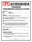
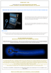
1
YOSHIMURA PIM II
(EMS Peripheral Interface Module)
APPLICATION
YEAR
2012
MODEL
KTM SX-F 250
PRODUCT
600XX262500
PIM2 Fuel Injection Controller Kit
This product is designed for use in closed course racing and is not
intended for highway use.
Read through all instructions before beginning installation.
Areas of vehicle may be extremely hot. Let motorcycle cool down
before beginning installation. Always wear hand and eye protection
and take precautionary measures to avoid injury or damage.
NOTE:
In the state of California, it is illegal to modify the emission control system, which includes the fuel injection of any
vehicle for on- or off-highway vehicles.
TOOL REQUIRED
Metric Socket Set
-INSTALLATION-
1. Remove seat, fuel tank, radiator shrouds, and air box cover as per factory
service or owner’s manual.
2. Route harness through left side of air box, following the positive (+) cable
as shown in Fig 1.
5420 Daniels Street Chino, CA 91710 Tel (800) 634-9166 Fax (909) 591-2198 www.yoshimura-rd.com
600XX262500
Page 1 of 4
PIM2/BRACKET
Power
Connecter
Harness to TPS,
CPS, and Injector
Fig 1.
3. Locate and disconnect stock, black Throttle Position Sensor (TPS) found
on left side of throttle body as shown in Fig 2. Connect PIM2 harness
connectors to the TPS and connector.
TPS Connector
Fig 2.
4. Locate and disconnect stock black Fuel Injector plug as shown in Fig 3.
Connect PIM2 harness connectors to fuel injector and connector.
Fig 3.
5420 Daniels Street Chino, CA 91710 Tel (800) 634-9166 Fax (909) 591-2198 www.yoshimura-rd.com
600XX262500
Page 2 of 4
5. Locate and disconnect blue Crank Position Connector located just ahead
of the ECU beneath the tank. Connect PIM2 harness connectors to
crank position connectors.
Crank Position
Connector
Fig 4.
6. Locate and disconnect clear Power Source connector located just behind
the ECU as shown in Figure 5. Connect PIM2 harness connectors to
power source connectors as shown in Figure 5.
Power Source
Connectors
PIM2
Connectors
Fig 5.
7. Install PIM2 unit and bracket as shown in Figure 1. Secure bracket to
subframe using supplied cable ties. Secure PIM2 unit to bracket using
supplied hook-and-loop adhesive. Connect PIM2 to PIM2 harness.
8. Reinstall air box cover, radiator shrouds, tank, and seat as per factory
service manual or owner’s manual.
5420 Daniels Street Chino, CA 91710 Tel (800) 634-9166 Fax (909) 591-2198 www.yoshimura-rd.com
600XX262500
Page 3 of 4
-PARTS DIAGRAM-
(S=Stock)
Injector Connectors
Map Selector
Power
Connector
Throttle Position
Connector
Crank Position
Connector
DATA
Connector
To PIM2 Unit
DESCRIPTION
PIM2 Unit
PIM2 Harness for KTM SX-F 350
PIM2 Bracket for KTM SX-F 350
Installation CD
Installation Instructions
USB Communication Cable
Cable Ties
Hook-and-loop Adhesive
Yoshimura Sticker Sheet
QTY
1
1
1
1
1
1
8
1
1
PART #
R-433B
600XX26350HB
600XX26350B
R-433-CD
INST KIT
R-433-USB
ZT-300
5000-V
17029
5420 Daniels Street Chino, CA 91710 Tel (800) 634-9166 Fax (909) 591-2198 www.yoshimura-rd.com
600XX262500
Page 4 of 4
Fuel Map Selector Switch
Operation & Use
The PIM comes with two preprogrammed maps. Install
and load software to see detailed information of map. See
‘Comment’ line in program for application detail.
Map 1
is active
Use the map selector plug to switch between maps. Map
1 is active when the selector plug is connected. Map 2 is
active while the selector plug is disconnected.
NOTE: Before connecting the map selector plug remove
the map selector plug cover.
Map 2
is active
Map
selector
plug cover