1
General Unofficial Mounting Instructions
I
n an effort to supplement the Öhlins Mounting Instructions I have created this pictorial from actual
experiences.
1. Nomenclature
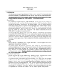
2. Pull the shock out of the box and familiarize yourself with the parts shown above.
a.
Legal Disclaimers to protect myself
i. It is advisable to have an Öhlins dealer install the shock absorber.
ii. When installing, consult your Vehicle Service Manual.
3. All models;
a. Remove Present Shock Absorbers.
b. Install the sleeve (converts metric to SAE) in the bottom eye
(#2) than install the ½”x 13 x 2 ½” bolt and washer through
the outside eye than affix shock and bolt to the swing arm.
Snug using your washer and ½”x 13 nut. No washer
(spacers) should be necessary unless the swing arm and
frame is out of alignment commonly found in 1986 ~ 2008
FLT’s or clearance problems are caused by aftermarket
accessories.
c. Rotate shock upwards so the top bolt mounting hole in the
frame aligns with the cylinder head bolt hole.
d. Look from the rear forward at the space (if any) between the
frame and the cylinder head (#1).
e. Add the appropriate amount of spacer(s) to shim the shock
to eliminate the gap if needed.
Caution! Under no circumstances ever tighten the mounting bolt to close the gap.
1. Sag Set Up
a. Your shocks are delivered by me with the Pre-Load collar
set with only a few threads showing at the top. You are
the only one that can set your spring pre-load on your
bike correctly.
b.
Measure the total length of the shock in any method
you wish with the wheel slightly off of the ground. An
easy way is to rotate the “Flats” of the shock mounting
bolts. I recommend a caliper that is at least 14” long. A
cheap solution is a Harbor Freight:
c. If you own a FLT this measurement is what you will get
from 28 mm of total sag if you weigh 204#. (next picture)
d. In this instance the total length from bolt from outside flat
of the bolt to the bottom outside flat of the bolt with the
wheel off of the ground was 349 mm. When the subject
set on the bike and feet up on the boards and jack
removed, the total sag was 28 mm as measuring from the
same point, the shock length is 321 mm. This is a 220 mm
X 25 N/m spring only. Write it down!
e. Have a friend steady the bike by the handlebars and the
rider sits on the bike with the wheel on the ground if
measuring for single up. For two up both riders get on the
bike with feet up on the pegs just like you are riding.
f. Look on my site and determine what your stroke is. Divide
the stroke by 1/3rd. A #3~#3 looks like this: #3~#3: 329
+5mm/- 5 mm = low of 12 ¾”~13 9/64, Stroke: 3
1/32"/77mm.
g. Depending where the height adjuster is adjusted to,
measure from your reference point (R-1).
h. Divide the stroke by 1/3rd (77mm) 3 ÷ = 25.66 mm.
i. (R-1) - 1/3rd stroke = (R-3) target (with the above rider(s)
on the bike).
Please remember that over 500 miles your shocks will
break-in and have different ride characteristics than new.
Look at this spring pre-load collar in relation to the top
seal head, that bike that I personally measured both
initially and now. The spring pre-load collar was set similarly to the
above shock on the FLT. The length of the shock (with
like height adjuster length) is exactly the same. 1/3rd
the stroke (rebound) is inside of the shock.
The Springs Play No Part in This
Suspension Other Than To Overcome
Gravity!
Dampening Sweep Valve
How it works:
The shock shaft is hollow and assembly
#1 is inserted inside of the shaft with
the needle valve inside of the shaft. This
needle valve lets oil from either side of
the piston (top is rebound & bottom
side is compression) bypass the shim
stacks to the other side of the piston.
This controls the percentage of oil goes
through shim stacks which is how you
adjust the shock for ride quality. Again:
The Springs Play No Part in This
Suspension Other Than To Overcome
Gravity!
The #1 assembly is inside of the (simplified) shaft
than the solid rod (#2) is pushed through the oblong
hole not allowing the needle valve shaft to fall down.
The solid rod pushed up or down on the #1
assembly, it is spring loaded (not shown). The black
adjuster knob (#3) is than screwed onto the bottom
of the shaft. The solid rod (#2) is against the black
adjuster knob where there is a machined from billet
adjuster “Detent” ring which the solid rod rests in
and that is what makes the clicking sound and feel.
Under extreme pressure the “Detents” can sheer
when the damper knob is forced to that “Last” click.
You must hold your fingers out like a safecracker and
apply minimal pressure and do not force it. Please
remember when the steel ground solid rod stops
going up (#2) and you still keep on cranking the “Detents” of the aluminum detent ring will get sheared
off much sooner than you will wear down a solid steel shaft that is supported 1/8” from the end of the
overhang of the shock shaft (#2).
Adjusting the Damping
An easy way to adjust initially for touring street riding is to place a tie wrap around the
shock shaft, cut the tail, and push it up to the shock body (Red Arrow). Now you can
visually know how much stroke you are using but be careful going out of your driveway.
Test on a road you are normally going to ride on.
This valve is the only place you will get your ride quality. Right or clockwise allows more
oil flow through the piston (more resistance to change) and less
oil to bypass the piston through the hollow shaft and out the
shaft. Left or counterclockwise allows less oil to push on the
shim stack and more oil to bypass the piston (more resistance
to change). You are looking up on the shock from the bottom
of the shock to determine which way is clockwise as reference.
The more resistance to change the harder it is to
move and the less the stroke you will use over a
given road irregularity. Try to adjust so the tie
wrap is near the bump stop. A large bump that is
infrequently experienced will stop hard parts from hitting thus protecting
against damage.