1
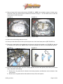
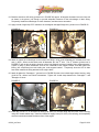
43. Scrape off the excess factory sealant. Apply a new bead of high temp. RTV sealant to the oil pan sealing
surface, and re-install the oil pan.
44. Remove the factory exhaust system (SEE FIGURE 38) from the 3-bolt manifold-to-CAT flange back to the 2bolt flange (just before the first muffler).
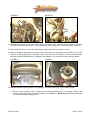
45. Cut a length of heat shield wrap (P/N 31007) to 5.0 feet. Wrap P/N 21184 (Exh. Tube Ass’y, Turb. Housing
Inlet) as seen in FIGURE 41. The heat wrap is adhesive backed, so it should stay in place, but as an added
measure you may want to secure the end with a zip tie or steel wire.
FIGURE 40
FIGURE 41
NOTE: During the next few steps, only loosely secure the new exhaust tubes in place. Once all exhaust
tubes are loosely installed, go thru and tighten all the hardware & clamps.
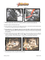
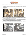
46. Loosen the left factory hex bolt and remove the right hex bolt holding the A/C compressor in place (pointed
out in FIGURE 42). Install P/N 21184 (Exh. Tube Ass’y, Turb. Housing Inlet) tube into position as shown in
FIGURE 43, using the A/C bolts to loosely secure it in place.
FIGURE 42
LEFT
FIGURE 43
RIGHT
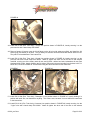
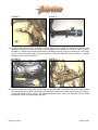
47. Either before or after loosely installing the “Turb. Housing Inlet” tube, install the “Turbo Support Bracket” (P/N
21202) circled in FIGURE 44, by loosening another of the A/C compressor bolts (on the driver’s side top), and
sliding the slotted end of the bracket under the loosened A/C bolt. The end of the bracket with the hole
should line up with one of the holes in the turbocharger inlet flange (SEE FIGURE 44).
60130_revC.doc
Page 21 of 32