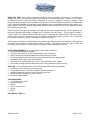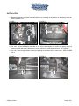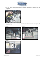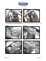
1
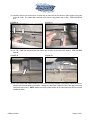
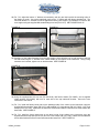
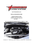
INSTALLATION INSTRUCTIONS
Intercooler Upgrade Kit
’04-’06 Ford 6.0L – P/N 70057
’99-’03 Ford 7.3L – P/N 70058
Turbonetics, Inc. * 14399 Princeton Avenue * Moorpark, CA * 805-581-0333 * TurboneticsInc.com
READ THIS FIRST: Study these instructions completely before proceeding. Engine and / or turbocharger
damage may occur if any component within these instructions is improperly installed. Turbonetics, Inc or any of
its distributors cannot be held responsible for damages as a result of negligent or improper installation. This
complete turbocharger system can be installed using common tools and automotive procedures, but installer must
have a thorough knowledge of automotive engine operation and feel comfortable working on the vehicle. If in
doubt, contact Turbonetics’ technical support staff at 805-581-0333, between the hours of 8:00AM and 5:00PM
PST, Monday through Friday.
Remove the heat exchanger from its carton and inspect for any obvious physical damage. All kit components are
thoroughly inspected and carefully packaged prior to shipment from the factory. If any shipping damage is
evident, contact your supplier and request that they process a claim with the shipper involved. Be sure to review
the parts list on page 2 to verify that you have all necessary system components to proceed. If any components
in the parts list are missing, contact Turbonetics’ customer service staff.
The information contained in this publication was accurate and in effect at the time the publication was approved
for printing and is subject to change without notice or liability. Turbonetics reserves the right to revise the
information presented herein or to discontinue the production of parts described at any time.
SAFETY REQUIREMENTS: It is recommended to follow these precautions.
• Always wear safety glasses & gloves.
• Turn the ignition switch to the OFF position & disconnect the batteries.
• Always use properly rated jack stands when working under the vehicle.
• Prevent unexpected vehicle movement by using wheel chocks and/or parking brake.
• Operate the vehicle only in well ventilated areas.
• Do not smoke or use flammable items near or around the vehicle’s fuel system.
• Keep hands, clothing and other objects away from moving parts when engine is running.
SUPPLIES: It is recommended to have the following items before beginning installation.
• Ford factory service manual, for your model year
• A large table or bench, and plenty of adjacent available workspace
• Standard selection of automotive tools, primarily metric sizes
• Medium strength threadlocker (Loctite or equiv.)
• Std silicone sealer/adhesive
TOOLS REQUIRED:
• 8, 11& 12mm Deep socket
• Socket Extension
• Ratchet
• 10mm, 12mm Wrench
• Pry bar
• Pliers
EST. INSTALL TIME: 2 Hr.
60204_revA.doc
Page 2 of 21
PARTS LIST – P/N 70058 – Ford 7.3L
Part Number
Description
70065
Intercooler Assembly
11568
Hardware Kit
22172
Silicone Hump Trans Hose, 3.00”-3.25”
22173
Silicone Hump Hose, 3.00”
30315
License Frame – Turbonetics
31317-300
Hose Clamp, T-Bolt Spring 3.00
31317-325
Hose Clamp, T-Bolt Spring 3.25
31364
Box Insert, 25.0 x 3.5” cardboard
60205
Instruction Packet
Quantity
1
1
1
1
1
3
1
2
1
PARTS LIST – P/N 70057 – Ford 6.0L
Part Number
Description
70056
Intercooler Assembly
21472
Tube Ass’y, I/C to engine
21525
Silicone Hump Hose, 3.0” (w/ internal bead)
22174
Silicone Hump Hose, 3.0”
30315
License Frame – Turbonetics
31317-300
Hose Clamp, T-Bolt Spring 3.00
60205
Instruction Packet
Quantity
1
1
1
1
1
4
1
HARDWARE KIT – P/N 11568 (only included with 70058 - Ford 7.3L)
Part Number
Description
22084
Rubber Spacer, 3/8” ID x 1.0” OD
22085
Spacer Block, Hood Latch
22086
“L” Bracket, IC Support
30576-40
Bolt, M8-1.25 x 40mm, Hex Head
30591
Washer, Flat, M6
30593
Washer, Lock, M8
30596
Washer, Split Lock, M6
30807
Washer, Flat, M8 x 30mm OD
31067
Mount, Vibration Damping, M6
31312
Hex Nut, M6-1.0 Wizlock
31313
Hex Head Bolt, M6-1.0 x 30mm
31314
Hex Head Bolt, M6-1.0 x 20mm, Wizlock
Quantity
4
2
2
2
2
2
2
2
2
2
2
2
INSTRUCTION PACKET – P/N 60205 (included with both Ford 7.3L and 6.0L)
Part Number
Description
Quantity
21415
Badge, Polydome
2
22035
Spacer Block, Rubber
2
60204
Install Instructions, Ford 7.3L/6.0L I/C Kit
1
60204_revA.doc
Page 3 of 21
INSTALLATION
1.) Disconnect negative terminals from both batteries by loosening the 8mm bolts on the battery terminals.
SEE FIGURES 1 & 2
FIGURE 1
FIGURE 2
2.) For 6.0L, remove both battery terminals on the driver’s side battery and remove the battery cover by
pulling upwards and remove the battery out of the vehicle by unbolting the 8mm bolt. SEE FIGURE 1.
3.) For 6.0L, Remove upper radiator mounts by unbolting the two 8mm bolts on each mount. SEE FIGURES
3 & 4.
FIGURE 3
60204_revA.doc
FIGURE 4
Page 4 of 21
4.) For 7.3L, Remove the wing nut that secures the emergency jack and tools in the engine bay. SEE
FIGURE 5.
FIGURE 5
5.) For 7.3L, Remove the five 8mm bolts that secure the upper radiator mount to the core support. SEE
FIGURES 6 to 8.
FIGURE 6
FIGURE 7
FIGURE 8
60204_revA.doc
Page 5 of 21
6.) For 7.3L, Remove three 8mm bolts securing radiator overflow tank to the truck. SEE FIGURES 9 & 10.
NOTE: Do not remove the coolant tank completely out of the vehicle.
FIGURE 9
FIGURE 10
7.) For 7.3L and 6.0L, remove the four plastic snap in fasteners that secures the plastic trim to the core
support. SEE FIGURES 11, 12, 13 & 14 (6.0L).
FIGURE 11
FIGURE 12
FIGURE 13
FIGURE 14
60204_revA.doc
Page 6 of 21
8.) For 7.3L and 6.0L, use a marker and mark the location of the hood latch in relative to the core support,
this will help latch alignment during re-assembly. SEE FIGURES 15 & 16.
FIGURE 15
FIGURE 16
FIGURE 17
9.) For 7.3L and 6.0L, carefully unclip the plastic fastener that secures the hood latch cable to the core
support. SEE FIGURE 18.
FIGURE 18
60204_revA.doc
Page 7 of 21
10.) For 7.3L and 6.0L, unbolt the two 8mm bolts for the upper A/C condenser brackets. SEE FIGURES 19,
20 (6.0L) and 21, 22 (7.3L).
FIGURE 19
FIGURE 20
FIGURE 21
FIGURE 22
11.) For 6.0L, remove the air filter and then the plastic intake tube that goes from the front of the truck to the
filter. SEE FIGURE 23.
FIGURE 23
60204_revA.doc
Page 8 of 21
12.) For the 7.3L, remove the plastic intake tube that goes from the intake box to the front of the truck by lifting
the cover and depressing the tab from inside the box on each side of the tube. SEE FIGURES 24-27.
FIGURE 24
FIGURE 25
FIGURE 26
FIGURE 27
13.) For 7.3L and 6.0L, remove two 10mm bolt that secures the factory intercooler to the core support. SEE
FIGURES 28, 29 (6.0L) and 30, 31 (7.3L).
FIGURE 28
60204_revA.doc
FIGURE 29
Page 9 of 21
FIGURE 30
FIGURE 31
14.) For 7.3L and 6.0L, using a 12mm open wrench or socket, remove the eight bolts that secure the core
support to the chassis. SEE FIGURES 32-35.
FIGURE 32
FIGURE 33
FIGURE 34
FIGURE 35
60204_revA.doc
Page 10 of 21
15.) Ford 7.3L and 6.0L, carefully pry the top core support out with a pry bar without scratching it. SEE
FIGURES 36 & 37.
FIGURE 36
FIGURE 37
16.) For 6.0L, remove the driver’s side boost tube (some years may come with a plastic boost tube while
others may come with a steel tube). SEE FIGURES 38 & 39.
FIGURE 38
60204_revA.doc
FIGURE 39
Page 11 of 21
17.) For 6.0L, loosen the hose clamp that secures the boost tube from the turbo to the intercooler on the
passenger’s side. SEE FIGURE 40.
FIGURE 40
18.) For 7.3L, loosen the hose clamps on both driver and passenger side boost tube. SEE FIGURES 41 & 42.
FIGURE 41
60204_revA.doc
FIGURE 42
Page 12 of 21
19.) For 7.3L & 6.0L, slowly remove the factory intercooler out of the vehicle by lifting upwards. SEE FIGURE
43. NOTE: Be careful of when working around the A/C lines, the lines are soft and can be bent slightly
out of the way easily.
FIGURE 43
20.) For the 7.3L, remove the rubber flap on the bottom of the bumper. The flap is secured to the bumper with
plastic snap in clips. This will allow you to gain access to install the lower support brackets on the new
Spearco intercooler. SEE FIGURES 44 & 45.
FIGURE 44
60204_revA.doc
FIGURE 45
Page 13 of 21
21.) Carefully remove the small section of rubber flap on each side of the vehicle to gain access to the bolts
on the oil cooler. The rubber flap is secured to the vehicle using plastic snap in clips. SEE FIGURES 46
& 47.
FIGURE 46
FIGURE 47
22.) For 7.3L, unbolt the two M6 screws that secure the oil cooler to the lower core support. SEE FIGURES
48 & 49.
FIGURE 48
FIGURE 49
23.) For 6.0L, remove the rubber isolator from the lower mounting brackets of the factory intercooler and reinstall it onto the new Spearco intercooler. Making sure the rubber isolator is flush to the edge of the new
intercooler lower mount. NOTE: Adhere the factory rubber isolator to the intercooler with silicone to make
installation easier.
60204_revA.doc
Page 14 of 21
24.) For the 7.3L, install the new supplied rubber isolator (PN 22035) to the lower mounting brackets of the
Spearco intercooler. Making sure the rubber isolator is flush to the edge of the new intercooler lower
mount. SEE FIGURE 50 & 51. NOTE: Adhere the factory rubber isolator to the intercooler with silicone
to make installation easier.
FIGURE 50
FIGURE 51
25.) For 7.3L, install the supplied lower support “L” brackets to the threaded boss on the bottom of the new
intercooler using the supplied M6 rubber isolators (PN 31067) and M6 serrated flange hex nut (PN
31312). Apply threadlocker to both sides of the thread on the supplied rubber isolator. Hand tighten the
serrated flange hex nut to the rubber isolator. SEE FIGURES 52-57. NOTE: Notice the orientation of the
L brackets to the hose connectors on the intercooler. SEE FIGURE 56 & 57.
FIGURE 52
FIGURE 53
“L” Bracket PN 22086
60204_revA.doc
Page 15 of 21
FIGURE 54
FIGURE 55
FIGURE 56
FIGURE 57
HOSE CONNECTORS
FACING DOWNWARDS.
“L” BRACKETS FACING
UPWARDS.
26.) For 7.3L, carefully slide the new intercooler into the vehicle. The two bottom “L” brackets should line up
with the mounting holes of the factory oil cooler. SEE FIGURE 58.
FIGURE 58
60204_revA.doc
Page 16 of 21
27.) For the 7.3L, insert the 2 supplied cardboard spacers (PN 31364) between the intercooler and the
radiator. Insert the spacers diagonally where the bottom edge of the spacers would rest on the ledge of
the radiator core and the top side resting on the hose connector of the intercooler. SEE FIGURES 59-63.
FIGURE 59
FIGURE 60
FIGURE 61
FIGURE 62
FIGURE 63
60204_revA.doc
Page 17 of 21
28.) For 7.3L, adjust the bottom “L” brackets as necessary until they are lined up with the mounting holes of
the factory oil cooler. Line up the machined notch on the “L” bracket with the factory threaded clip. The
notch will allow the “L” bracket to sit flush against the factory core support. Re-install the oil cooler to the
core support using the supplied M6 serrated flange hex bolt (PN 31314). SEE FIGURES 64 & 65.
FIGURE 64
FIGURE 65
29.) Carefully pry the rubber flap away from the core support, which will allow you to gain access to the hex
nut that is securing the “L” bracket to the rubber isolator on the bottom of the intercooler. Using a long
extension and a socket, tighten nuts on both brackets. SEE FIGURE 66.
FIGURE 66
30.) Using the supplied M8-1.25 hex bolt (PN 30576-40), M8 fender washer (PN 30807), and 4 supplied
rubber spacers (PN 22084), with one on each side of the top intercooler bracket. Secure the new
intercooler to the vehicle.
31.) For 7.3L, install the factory boost tube on the passenger side of the vehicle to the intercooler using the
supplied silicone transition hose (PN 22172) and supplied 3.0” t-bolt clamps (PN 31317-300), 3.25” t-bolt
clamps (PN 31317-325). Make sure the side with a hose bead inside the silicone hose faces toward the
boost tube. SEE FIGURE 67.
32.) For 7.3L, install the factory boost tube on the driver’s side of the vehicle to the intercooler using the
supplied silicone hump hose (PN 22173) and 3.0” t-bolt clamps (PN 31317-300). Make sure the side with
a hose bead inside the silicone hose faces toward the boost tube. SEE FIGURE 68.
60204_revA.doc
Page 18 of 21
FIGURE 67
FIGURE 68
33.) For 6.0L, install the new supplied stainless boost tube (PN 21472) that connects the intercooler to the
engine using the supplied 3.0” t-bolts clamps (P/N 31317-300), silicone hump connector (PN 22174), and
silicone hose adapter (PN 21525). SEE FIGURE 69.
FIGURE 69
INTAKE SIDE
INTERCOOLER SIDE
BOOST TUBE P/N 21472
60204_revA.doc
WELD LINE
Page 19 of 21
34.) Install the boost tube (PN 21472) in between the intercooler and the intake manifold using the supplied
silicone hump hose (PN 22174) and two 3.0” t-bolt clamp (P/N 31317-300) on the intercooler side and the
silicone hose adapter (PN 21525) and two 3.0” t-bolt clamp (PN 31317-300) on the intake manifold side.
SEE FIGURES 70 & 71.
FIGURE 70
FIGURE 71
35.) For 6.0L, when installing the new supplied silicone hose adapter (PN 21525), the side with the bead on
the inside of the hose goes on the engine side. Re-install the factory hood latch making sure the latch
lines up with the lines marked on the core support earlier.
36.) For 7.3L, re-install the factory hood latch with supplied spacers (PN 22085) in between the hood latch and
the core support and secure using supplied M6-1.0x30mm bolts (PN 31313) and M6 washers (PN
30591). SEE FIGURES 72-73.
FIGURE 72
FIGURE 73
37.) Re-install the remaining factory pieces (rubber flaps and plastic trims).
38.) Complete.
60204_revA.doc
Page 20 of 21
FINAL CHECKLIST:
•
Review these instructions to make sure that all fasteners, clamps connections have been installed correctly.
•
Check that all hose routings are free of any kinks or near any hot or abrasive surfaces, which may cause wear
over time. Adjust or reroute as necessary to provide adequate slack for engine movement.
“NO FAULT / NO HASSLE” WARRANTY PROGRAM:
TURBONETICS will repair or replace, at our expense, any new TURBONETICS / SPEARCO products that fail,
including products used in racing or competition applications, for a period of one year from the original date of
purchase. All turbocharger and cartridge assemblies have a factory installed inline oil filtration device. This filter
device must remain in place if any warranty is to be considered under the No-Fault / No-Hassle program.
Electrical components that fail due to misuse are not covered under the No-Fault / No-Hassle Warranty Program.
Warranty is limited to TURBONETICS products and does not include progressive or sub sequential damage and
does not cover removal or installation labor or associated parts. No warranty is made for any other claims for
special, indirect or consequential damages including but not limited to component removal or installation
equipment downtime, prospective profits or other economic loss.
Warranty will not be granted for recurring damage, malfunction, or failure due to improper installation, misuse,
unauthorized repair or alterations, or externally induced physical damage.
Warranty is non-transferable and must be processed via the original purchaser from TURBONETICS.
Remanufactured units, performance upgraded units, and O.E.M. replacement units are covered by a 90-day
warranty or the O.E. warranty period.
TURBONETICS highly recommends that the installation of mechanical or electrical parts be performed by trained
professionals. Improperly installed products may lead to unsafe and unreliable conditions.
RETURN POLICY:
Only unused and complete merchandise may be accepted for return subject to inspection and acceptance by
TURBONETICS. No goods will be accepted without prior return authorization from TURBONETICS. Call for
approval and RGA (Returned Goods Authorization) tracking number. No returns will be accepted without an RGA
tracking number. No returns will be accepted after ninety (90) days from the original shipping date from
TURBONETICS unless approved. All approved returns are subject to a 15% restocking charge – NO
EXCEPTIONS. The original invoice must accompany the return. Accepted warehouse / distributor and open
account returns will be issued credit only.
RETURNED GOODS AUTHORIZATION TRACKING NUMBER:
TURBONETICS will only accept product returns, repair orders / upgrades, and warranty requests that have been
approved and are returned with a corresponding RGA (Returned Goods Authorization) tracking number.
Contact TURBONETICS for approval and the RGA number. Write the RGA number clearly on the outside of the
package and include it inside the package. This is very important in allowing us to properly identify and process
your request. Failure to comply with this requirement will result in the delay of processing or the product being
returned to you.
60204_revA.doc
Page 21 of 21