1
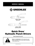
SERVICE MANUAL 7804SB / 7806SB Quick Draw® 7704SB / 7706SB Quick Draw® Flex Quick Draw Hydraulic Punch Drivers ® Serial Codes AHJ and YZ Read and understand all of the instructions and safety information in this manual before operating or servicing this tool. Register this product at www.greenlee.com 99947323 REV 1 © 2011 Greenlee Textron Inc. 4/11 Quick Draw® Hydraulic Punch Drivers Table of Contents Safety Safety............................................................................. 2 Purpose of this Manual.................................................. 2 Other Publications.......................................................... 2 Important Safety Information......................................... 3 Maintenance................................................................... 4 Troubleshooting.............................................................. 5 Disassembly................................................................... 6 Ball Seat Repair.............................................................. 6 Reassembly.................................................................... 7 Inspection and Adjustments........................................... 7 Illustrations and Parts Lists.......................................8–11 7704SB / 7706SB....................................................8–9 7804SB / 7806SB................................................10–11 Draw Studs and Accessories....................................... 12 Safety is essential in the use and maintenance of Greenlee tools and equipment. This manual and any markings on the tool provide information for avoiding hazards and unsafe practices related to the use of this tool. Observe all of the safety information provided. Purpose of this Manual This manual is intended to familiarize all personnel with the safe service procedures for the following Greenlee tools: 7704SB / 7706SB Serial Code AHJ 7804SB / 7806SB Serial Code YZ Keep this manual available to all personnel. Replacement manuals are available upon request at no charge at www.greenlee.com. Other Publications Instruction Manual: 99947307 All specifications are nominal and may change as design improvements occur. Greenlee Textron Inc. shall not be liable for damages resulting from misapplication or misuse of its products. Quick Draw is a registered trademark of Greenlee Textron Inc. Loctite and 242 are registered trademarks of Loctite Corporation. KEEP THIS MANUAL Greenlee / A Textron Company 2 4455 Boeing Dr. • Rockford, IL 61109-2988 USA • 815-397-7070 Quick Draw® Hydraulic Punch Drivers IMPORTANT SAFETY INFORMATION SAFETY ALERT SYMBOL Wear eye protection when operating or servicing this tool. Failure to wear eye protection could result in serious eye injury from flying debris. This symbol is used to call your attention to hazards or unsafe practices which could result in an injury or property damage. The signal word, defined below, indicates the severity of the hazard. The message after the signal word provides information for preventing or avoiding the hazard. • Inspect tool for wear or damage. Replace any worn, damaged, or missing components with Greenlee replacement parts. A damaged or improperly assembled tool can break and strike nearby personnel with sufficient force to cause severe injury or death. • Inspect the punch, die, draw stud, and spacers for wear or damage. Replace any worn or damaged items with Greenlee replacement parts. Replace any punches that have dull cutting surfaces. Immediate hazards which, if not avoided, WILL result in severe injury or death. Hazards which, if not avoided, COULD result in severe injury or death. Do not exceed the rated capacity of this tool. Exceeding the rated capacity could cause a component failure, which could throw broken parts with great force. Failure to observe this warning could result in severe injury or death. Hazards or unsafe practices which, if not avoided, MAY result in injury or property damage. Read and understand all of the instructions and safety information in this manual before operating or servicing this tool. Refer also to the instruction manual, which is listed under “Other Publications.” Failure to observe this warning could result in severe injury or death. Do not operate the pump lever after the ram motion stops. Continuing to operate the pump lever after the ram motion stops will damage the driver and could propel internal parts with great force, striking nearby personnel. Electric shock hazard: Do not use this tool near live circuits. This includes, but is not limited to, the following: • Near circuit breaker panels or fuse boxes with energized circuits. • Near junction boxes with energized circuits. Failure to observe this warning could result in severe injury or death. Greenlee / A Textron Company Use this tool for the manufacturer’s intended purpose only. Use other than that which is described in this manual can result in injury or property damage. Note: Keep all decals clean and legible, and replace when necessary. 3 4455 Boeing Dr. • Rockford, IL 61109-2988 USA • 815-397-7070 Quick Draw® Hydraulic Punch Drivers Maintenance Maintenance and repairs should be performed in a dustfree area by qualified technicians. This unit requires minimum maintenance because it has a closed hydraulic system and all internal parts are lubricated by the hydraulic fluid. Lubricate lever pins lightly. Keep contaminants away from the ram and cylinder. Store with the lever down and hydraulic p ressure released. Reservoir Handle Lever Handle Adding Hydraulic Oil 1. Place the driver in a vise in a vertical position with the handles up. Unscrew the reservoir handle and remove the bladder plug. Open the release valve knob to assure the ram is fully extended. 2. Fill the rubber bladder to the point of overflow with Greenlee hydraulic oil. 3. Purge air from the system: Pump the lever handle several times to remove air from the pumping chamber. Close the release valve knob and pump the lever handle until the ram completes its full travel. Repeat as necessary. Note: Open the release valve knob slowly so the ram extends slowly. Rapid return of oil and air may cause the oil to overflow the rubber bladder. If this procedure fails to remove air, remove the bladder plug and open the release valve knob. Place thumb over the plug hole in the bladder and squeeze the bladder while pumping the lever handle several times. Close the release valve knob and pump the lever handle until the ram completes its full travel. Repeat as necessary. If this procedure does not remove air, remove the plunger (24) and fill the plunger cavity with clean oil as described in the “Reassembly” section of this manual. 4. Fill the rubber bladder to the point of overflow and replace the bladder plug. Wipe the bladder clean of excess oil and reassemble the reservoir handle. Greenlee / A Textron Company Bladder Plug Rubber Bladder Release Valve Knob Oil Leaks • Check for external oil leaks. • Check that the release valve knob and stem are closed tightly and seating properly. • Remove the reservoir handle and check for oil leaks around the rubber bladder and bladder plug. 4 4455 Boeing Dr. • Rockford, IL 61109-2988 USA • 815-397-7070 Quick Draw® Hydraulic Punch Drivers Troubleshooting Problem Probable Cause Probable Remedy Does not punch hole. Improper assembly or use of punch, die, or accessories. Refer to “Operation” and “Capacity and Draw Stud Selection Guide” in the Instruction Manual. Low oil level. Refer to “Adding Hydraulic Oil” in the “Maintenance” section. Improper assembly or use of punch, die, or accessories. Refer to “Operation” and “Capacity and Draw Stud Selection Guide” in the Instruction Manual. Material being punched is too thick or too hard. Refer to “Capacity and Draw Stud Selection Guide” in the Instruction Manual. Pump does not build p ressure. Air in system. Refer to step 3 of “Adding Hydraulic Oil” in the “Maintenance” section. Excessive number of strokes are required to punch hole. Inoperative intake check valve. Refer to “Intake Check Valve” inspection in the “Inspection and Adjustments” section. Inoperative discharge check valve. Refer to “Discharge Check Valve” inspection in the “Inspection and Adjustments” section. Leaking release valve. Refer to “Release Valve” inspection in the “Inspection and Adjustments” section. Damaged piston, piston extension, pump plunger seals, or mating surfaces. Refer to “Maintenance,” cylinder and pump block sections. Clogged filter. Clean or replace filter (31). Does not return piston. Weak or damaged return spring; excess oil in unit. Refer to “Ram Travel Inspection” in the “Inspection and Adjustments” section. External oil leaks. Damaged piston, piston extension, pump plunger seals, or mating surfaces. Refer to “Maintenance,” cylinder and pump block sections. Damaged release valve stem seal. Refer to “Release Valve” inspection in the “Inspection and Adjustments” section. Requires excessive lever force. Greenlee / A Textron Company 5 4455 Boeing Dr. • Rockford, IL 61109-2988 USA • 815-397-7070 Quick Draw® Hydraulic Punch Drivers Disassembly Ball Seat Repair 1. Remove reservoir handle (1), and bladder plug (20); drain oil from the rubber bladder (29). 2. Remove O-ring retainer (35) and the rubber bladder (29). Remove retaining rings (21) from one end of both handle pins (30) and disassemble handle pins and lever handle (2). 3. Grasp plunger (24) with pliers; pull and twist to remove. Loosen set screw (12) from release valve knob (27); remove knob. Unscrew release valve stem (28) to remove from pump block (5). Ball (32) is also accessible. 4. Loosen set screw (12) from cylinder (4) and unscrew cylinder from pump block (5). 5. Remove compression spring (7), retaining plate (22) and ram coupler (26). Spring (23) and ball (37) can also be removed. 6. Screw a draw stud into end of ram (6); push the ram out of the cylinder (4). 7. Remove filter (31). Remove seat (3) and ball (32). Spring (13) will also be accessible. You have now disassembled the punch driver. Thoroughly clean all parts and inspect the three ball seats (intake, discharge and release valve stem) for nicks, scratches, or other damage. Re-seating Minor seat imperfections may be corrected by re-seating. Use a soft brass rod and hammer to tap the ball against its seat. Wear eye protection when operating or servicing this tool. Failure to wear eye protection could result in serious eye injury from flying debris. Re-drilling Badly worn or damaged seats may be reworked by re-drilling and then re-seating. The pump block is manufactured with seats of 118°, the standard drill point angle. Use standard drills for re-drilling. • To re-drill the 3/16" ball seat for release valve stem (28): Use an “I” drill and a 9/64" diameter reamer. • To re-drill the 7/32" ball seat for the discharge check: Use an “I” drill and a 5/32" diameter reamer. • To re-drill the 3/16" ball seat for the intake check: Use a 1/4" drill and a 1/8" diameter reamer. When drilling, remove a minimum of material to obtain maximum seat life. Re-seat the balls before reassembly. “I” Drill Discharge Check Std. Drill Acceptable “I” Drill 5/32" Ream Release Valve Stem “B” Drill 9/64" Ream Intake Check 9/64" Ream Greenlee / A Textron Company 6 4455 Boeing Dr. • Rockford, IL 61109-2988 USA • 815-397-7070 Quick Draw® Hydraulic Punch Drivers Reassembly Inspection and Adjustments Reassembly is done in reverse sequence of disassembly. 1. Use one of the following repair kits to replace all O-ring seals, balls, and springs: • 7704SB / 7706SB: Repair kit 501 0477.2 • 7804SB / 7806SB: Repair kit 503 7161.4 2. Inspect drilled oil passage in ram (6); be sure this passage is not blocked. 3. Before reinserting ram (6) in cylinder (4), lightly coat O-ring seals and bores of the cylinder with clean hydraulic oil. 4. Coat discharge check spring (23) with petroleum gel and insert it into the counter bore of the ram coupler (26). 5. Fill plunger bore in pump block (5) with clean oil. Then coat plunger O-ring seals with clean oil, and reinsert in the pump block with release valve knob (27) closed. 6. Fill unit with clean oil and purge air. Refer to “Adding Hydraulic Oil” in the “Maintenance” section of this manual. After reassembly, check the following: Ram Travel Inspection Ram Extended With the draw stud removed and release valve knob open, observe whether end of ram (6) is flush to 1/64" (0.396 mm) below the end of cylinder (4). If it is not, the rubber bladder (29) contains too much oil. To remove excess oil: 1. Remove reservoir handle (1) and bladder plug (20). 2. Slowly open release valve knob (27); excess oil should come out of the rubber bladder and the ram should move to become flush to 1/64" (0.396 mm) below the end of cylinder (4). 3. If excess oil does not come out, replace the compression spring (7). Ram Retracted Measure ram travel distance (difference between ram completely extended and completely retracted). Adjust cylinder (4) so travel distance is 0.830" (21.1 mm) to 0.930" (23.6 mm). Tighten set screw (12). (23.6 mm) (21.1 mm) .930" Piston .830" Travel 33967 Adapter Rotate cylinder to make adjustment. Set Screw (12) Pump Section Inspection Intake Check Valve Close the release valve knob and operate lever handle (2) until ram (6) bottoms and handle resistance increases. • If the ram bottoms in 30 strokes or less, the intake check valve is operating properly. • More than 30 strokes indicates an intake check leak. Re-seat, re-drill, or replace the intake check seat. Discharge Check Valve If the lever handle (2) returns to the raised position by itself, the discharge check valve is leaking. Re-seat or re-drill the discharge check seat and replace the discharge compression spring (23). Release Valve Pump the handle until the ram bottoms. Gently apply and maintain additional force on lever handle (2). If the lever handle remains solid, the release valve ball (32) is operating properly. If the lever handle (2) goes down slowly, the release valve is leaking. Re-seat or re-drill the release valve stem seat and replace O-ring (33). Greenlee / A Textron Company 7 4455 Boeing Dr. • Rockford, IL 61109-2988 USA • 815-397-7070 8 11 4 Greenlee / A Textron Company 42 41 22 9 26 10 14 15 6 23 21 30 37 21 7 33 40 5 24 34 34 36 8 3 12 33 33 32 32 13 32 32 18 43 39 28 31 27 35 20 38 1 50371606 Release Valve Unit Repair Kit includes items keyed in black circles (12, 16, 27, 28, 32, one of 33, 34) 50104772 Hydraulic Repair Kit includes items keyed in black squares (3, 8–11, 13–15, 21, 23, 31–37) 29 Repair Kits 16 2 19 Quick Draw® Hydraulic Punch Drivers Illustration—7704SB / 7706SB 4455 Boeing Dr. • Rockford, IL 61109-2988 USA • 815-397-7070 Quick Draw® Hydraulic Punch Drivers Parts List—7704SB / 7706SB Key Part No. Description 1 50368893 Handle, reservoir........................................................................................ 1 2 50368877 Handle, pump............................................................................................ 1 3 50368907 Seat, inlet check........................................................................................ 1 4 50342711 Cylinder, hydraulic...................................................................................... 1 5 50103903 Block weld assembly, pump...................................................................... 1 6 50103849 Ram............................................................................................................ 1 7 50342720 Spring, compression, 1.07 x 1.37 x 3.18................................................... 1 8 90538471 Backup ring, spiral, 1.00 x 1.24 x .027...................................................... 1 9 90513169 O-ring, 1.50 x 1.75 x .125 nitrile................................................................. 1 10 90538498 Backup ring, spiral, 1.50 x 1.74 x .027...................................................... 1 11 90513304 O-ring, 1.00 x 1.25 x .125 nitrile................................................................. 1 12 90552814 Screw, set #8-32 x .312 cup point............................................................. 1 13 50342878 Spring......................................................................................................... 1 14 90551214 Backup ring, spiral, .373 x .479 x .056...................................................... 1 15 90501683 O-ring, .364 x .500 x .068 nitrile................................................................. 1 16 50318780 Decal, punch release.................................................................................. 1 18 90511301 O-ring, 1.50 x 1.62 x .062 nitrile................................................................. 1 19 50232584 Grip, rubber................................................................................................ 1 20 50324888 Plug, bladder.............................................................................................. 1 21 90541863 Retaining ring, .217 Truarc......................................................................... 4 22 50103881 Retainer, coupler........................................................................................ 1 23 90538455 Spring, compression, .152 x .180 x .380................................................... 1 2450377159Plunger....................................................................................................... 1 26 50103865 Coupler, ram............................................................................................... 1 27 50368869 Knob, release valve.................................................................................... 1 28 50368931 Stem, release valve.................................................................................... 1 29 50342690 Bladder, rubber.......................................................................................... 1 30 50377140 Pin, handle................................................................................................. 2 31 52059251 Filter, oil...................................................................................................... 1 32 90506782 Ball, steel, .187 diameter........................................................................... 2 33 90538544 O-ring, .250 x .375 x .062.......................................................................... 2 34 90504585 Pin, roll, .125 x .375................................................................................... 1 35 90503767 O-ring, 1.125 x 1.375 x .12 nitrile............................................................... 1 36 90542304 Backup ring, spiral, .265 x .318 x .050...................................................... 1 37 90504526 Ball, steel, .218 diameter........................................................................... 1 38 50368940 Cap, reservoir handle................................................................................. 1 39 50103920 Hose........................................................................................................... 1 40 50103873 Retainer, spring.......................................................................................... 1 41 90541421 Ring, retaining............................................................................................ 1 42 50103938 Cover, hose................................................................................................ 1 43 50015923 Decal, identification.................................................................................... 1 Greenlee / A Textron Company Qty 9 4455 Boeing Dr. • Rockford, IL 61109-2988 USA • 815-397-7070 8 11 4 12 9 Greenlee / A Textron Company 10 23 21 10 37 30 21 6 33 5 24 7 34 34 18 36 32 32 12 32 32 33 33 13 22 28 3 15 14 26 16 27 31 35 2 1 38 50371606 Release Valve Unit Repair Kit includes items keyed in black circles (12, 16, 27, 28, 32, one of 33, 34) 50371614 Hydraulic Repair Kit includes items keyed in black squares (3, 8–11, 13–15, 18, 21, 23, 31–37) 20 Repair Kits 29 19 Quick Draw® Hydraulic Punch Drivers Illustration—7804SB / 7806SB 4455 Boeing Dr. • Rockford, IL 61109-2988 USA • 815-397-7070 Quick Draw® Hydraulic Punch Drivers Parts List—7804SB / 7806SB Key Part No. Description 1 50368893 Handle, reservoir........................................................................................ 1 2 50368877 Handle, pump............................................................................................ 1 3 50368907 Seat, inlet check........................................................................................ 1 4 50342711 Cylinder, hydraulic...................................................................................... 1 5 50369008 Block, pump............................................................................................... 1 6 50368966 Ram............................................................................................................ 1 7 50342720 Spring, compression, 1.07 x 1.37 x 3.18................................................... 1 8 90538471 Backup ring, spiral, 1.00 x 1.24 x .027...................................................... 1 9 90513169 O-ring, 1.50 x 1.75 x .125 nitrile................................................................. 1 10 90538498 Backup ring, spiral, 1.50 x 1.74 x .027...................................................... 1 11 90513304 O-ring, 1.00 x 1.25 x .125 nitrile................................................................. 1 12 90510321 Screw, set, #8-32 x .187 socket cup......................................................... 2 13 50342878 Spring......................................................................................................... 1 14 90551214 Backup ring, spiral, .373 x .479 x .056...................................................... 2 15 90501683 O-ring, .364 x .500 x .068 nitrile................................................................. 2 16 50318780 Decal, punch release.................................................................................. 1 18 90511301 O-ring, 1.50 x 1.62 x .062 nitrile................................................................. 1 19 50232584 Grip, rubber................................................................................................ 1 20 50324888 Plug, bladder.............................................................................................. 1 21 90541863 Retaining ring, .217 Truarc......................................................................... 4 22 50368923 Plate, retaining........................................................................................... 1 23 90538455 Spring, compression, .152 x .180 x .380................................................... 1 2450377159Plunger....................................................................................................... 1 26 50368915 Coupler, ram............................................................................................... 1 27 50368869 Knob, release valve.................................................................................... 1 28 50368931 Stem, release valve.................................................................................... 1 29 50342690 Bladder, rubber.......................................................................................... 1 30 50377140 Pin, handle................................................................................................. 2 31 52059251 Filter, oil...................................................................................................... 1 32 90506782 Ball, steel, .187 diameter........................................................................... 2 33 90538544 O-ring, .250 x .375 x .062.......................................................................... 2 34 90504585 Pin, roll, .125 x .375................................................................................... 1 35 90517415 O-ring, 1.31 x 1.56 x .125 nitrile................................................................. 1 36 90542304 Backup ring, spiral, .265 x .318 x .050...................................................... 1 37 90504526 Ball, steel, .218 diameter........................................................................... 1 38 50368940 Cap, reservoir handle................................................................................. 1 50376225 Decal, identification (not shown)................................................................ 1 Greenlee / A Textron Company Qty 11 4455 Boeing Dr. • Rockford, IL 61109-2988 USA • 815-397-7070 Quick Draw® Hydraulic Punch Drivers Draw Studs and Accessories Cat. No. Part No. Description 29451 50294512 Draw stud, 7/16" stainless steel (optional)....................................... 1 31872 50318721 Draw stud, 3/4–16 x 4.12................................................................. 1 1924AA 50332488 Spacer, .767 x 1.37 x .875................................................................ 1 1614SS 50300431 Screw, 3/8" short adapter................................................................ 1 33967 50339672 Adapter, stud, 3/8–24 x 3/4–16........................................................ 1 4455 Boeing Drive • Rockford, IL 61109-2988 • USA • 815-397-7070 An ISO 9001 Company • Greenlee Textron Inc. is a subsidiary of Textron Inc. www.greenlee.com USA Tel: 800-435-0786 Fax: 800-451-2632 Qty Canada Tel: 800-435-0786 Fax: 800-524-2853 International Tel: +1-815-397-7070 Fax: +1-815-397-9247