1
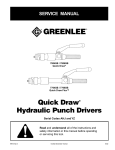
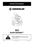
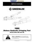
INSTRUCTION MANUAL
7804SB / 7806SB
Quick Draw®
7904SB / 7906SB
Quick Draw 90®
7704SB / 7706SB
Quick Draw Flex™
Quick Draw
Hydraulic Punch Drivers
®
Serial Codes AHJ, YZ, and ZA
Read and understand all of the instructions and
safety information in this manual before operating
or servicing this tool.
999 4730.7
© 2002 Greenlee Textron
8/02
Quick Draw® Hydraulic Punch Drivers
Table of Contents
Description
Description ..................................................................... 2
Safety ............................................................................. 2
Purpose of this Manual .................................................. 2
Other Publications .......................................................... 2
Important Safety Information ...................................... 3–4
Specifications ................................................................. 5
Capacity and Draw Stud Selection Guide ...................... 6
Operation ....................................................................... 7
Maintenance ................................................................... 8
Troubleshooting ............................................................. 9
Draw Studs and Accessories ....................................... 10
The Quick Draw® punch drivers are self-contained
hydraulic tools.
These punch drivers, when used with Greenlee
punches, dies, and draw studs, form a complete system
for punching holes of various shapes and sizes through
mild steel, aluminum, fiberglass, and plastic.
Slug-Splitter® punches, dies, and studs are available for
punching all of these materials as well as stainless steel.
In addition, the 7704SB / 7706SB punch driver has a
flexible body that allows hole punching at a variety of
angles. The handle and release mechanisms rotate
nearly 360° for convenient actuation.
Safety
Safety is essential in the use and maintenance of
Greenlee tools and equipment. This manual and any
markings on the tool provide information for avoiding
hazards and unsafe practices related to the use of this
tool. Observe all of the safety information provided.
Purpose of this Manual
This manual is intended to familiarize all personnel with
the safe operation and maintenance procedures for the
following Greenlee hydraulic punch drivers:
7704SB / 7706SB Quick Draw Flex™
7804SB / 7806SB Quick Draw®
7904SB / 7906SB Quick Draw 90®
Keep this manual available to all personnel.
Replacement manuals are available upon request at
no charge.
Other Publications
Service Manual:
7704SB / 7706SB: Publication 999 4732.3
7804SB / 7806SB: Publication 999 4732.3
7904SB / 7906SB: Publication 999 4731.5
All specifications are nominal and may change as design improvements occur. Greenlee Textron shall not be liable for damages
resulting from misapplication or misuse of its products.
Quick Draw Flex is a trademark and Quick Draw, Quick Draw 90,
Slug-Buster, and Slug-Splitter are registered trademarks of
Greenlee Textron.
KEEP THIS MANUAL
Greenlee Textron / Subsidiary of Textron Inc.
2
Quick Draw® Hydraulic Punch Drivers
IMPORTANT SAFETY INFORMATION
SAFETY
ALERT
SYMBOL
Electric shock hazard:
Do not use this tool near live circuits.
This includes, but is not limited to,
the following:
• Near circuit breaker panels or fuse
boxes with energized circuits
• Near junction boxes with
energized circuits
Failure to observe this warning can
result in severe injury or death.
This symbol is used to call your attention to hazards
or unsafe practices which could result in an injury or
property damage. The signal word, defined below,
indicates the severity of the hazard. The message
after the signal word provides information for
preventing or avoiding the hazard.
Immediate hazards which, if not avoided, WILL
result in severe injury or death.
Wear eye protection when operating
or servicing this tool.
Failure to wear eye protection can
result in serious eye injury from
flying debris.
Hazards which, if not avoided, COULD result in
severe injury or death.
Hazards or unsafe practices which, if not avoided,
MAY result in injury or property damage.
Read and understand all of the
instructions and safety information in
this manual before operating or
servicing this tool.
Failure to observe this warning can
result in severe injury or death.
Greenlee Textron / Subsidiary of Textron Inc.
3
Quick Draw® Hydraulic Punch Drivers
IMPORTANT SAFETY INFORMATION
• Inspect tool for wear or damage. Replace any
worn, damaged, or missing components with
Greenlee replacement parts. A damaged or
improperly assembled tool can break and strike
nearby personnel with sufficient force to cause
severe injury or death.
• Inspect the punch, die, draw stud, and spacers for
wear or damage. Replace any worn or damaged
items with Greenlee replacement parts. Replace
any punches that have dull cutting surfaces.
A component failure could throw
broken parts.
• Do not allow anyone to stand in
front of the punch or behind the
hydraulic ram.
• Close access doors or covers on
any equipment that is in line with
the punch or ram.
Failure to observe this warning can
result in severe injury or death.
Do not exceed the rated capacity of this tool.
Exceeding the rated capacity could cause a
component failure, which could throw broken parts
with great force.
Failure to observe this warning can result in severe
injury or death.
Do not attempt to punch a hole
through two or more layers of
material. This will bend or break the
draw stud and could throw parts
with great force.
Failure to observe this warning can
result in severe injury or death.
Do not operate the pump lever after the ram motion
stops. Continuing to operate the pump lever after the
ram motion stops will damage the driver and could
propel internal parts with great force, striking nearby
personnel.
Set up the tool properly. An improper setup could
cause a component to fail and strike nearby
personnel with great force.
• Thread the punch completely onto the draw stud.
All of the punch threads must be engaged by the
draw stud threads. Incomplete assembly could
cause a component failure.
• Use only Greenlee punches, dies, and draw
studs. Other manufacturers’ components might
not withstand the forces generated by this punch
driver.
Failure to observe these warnings can result in
severe injury or death.
Greenlee Textron / Subsidiary of Textron Inc.
Use this tool for the manufacturer’s intended purpose only. Use other than that which is described in
this manual can result in injury or property damage.
Note: Keep all decals clean and legible, and replace
when necessary.
4
Quick Draw® Hydraulic Punch Drivers
Specifications
Application Information
Refer to “Capacity and Draw Stud Selection Guide.”
Dimensions—7704SB / 7706SB Quick Draw Flex
Length
Without Draw Stud ..........................................................................406 mm (16.00")
With 3/4" Draw Stud ........................................................................482 mm (19.00")
Width (with handle extended) ..............................................................260 mm (10.25")
Mass/Weight ....................................................................................... 2.60 kg (5.75 lb)
Dimensions—7804SB / 7806SB Quick Draw
Length
Without Draw Stud ........................................................................321 mm (12.625")
With 3/4" Draw Stud ......................................................................397 mm (15.625")
Width (with handle extended) ..............................................................260 mm (10.25")
Mass/Weight ......................................................................................... 2.49 kg (5.5 lb)
Dimensions—7904SB / 7906SB Quick Draw 90
Overall Length .....................................................................................324 mm (12.75")
Mass/Weight ........................................................................................... 3.4 kg (7.4 lb)
Mechanical Data
Stroke (maximum) ....................................... 22 mm (0.850") minimum draw stud travel
Handle Force (maximum) ......................................................................... 356 N (80 lb)
Draw Stud Force (maximum) ....................................................... 71,168 N (16,000 lb)
Punch Diameter (maximum) ........ Refer to “Capacity and Draw Stud Selection Guide”
Material Thickness (maximum) .... Refer to “Capacity and Draw Stud Selection Guide”
Hydraulic Data
Circuit Type ........................................................................................................ Closed
Operating Pressure (maximum) ................................................... 44,480 N (10,000 lb)
Volume
Stroke .......................................................................... 0.034 cm3/mm (0.053 in3/in)
Usable ......................................................................................... 33.9 mm3 (2.07 in3)
Reservoir .................................................................................... 38.0 mm3 (2.32 in3)
Total ............................................................................................ 57.4 mm3 (3.50 in3)
Seals ...................................................... Nitrile, fluorocarbon, and Teflon backup rings
Fluid Compatibility: Compatible with hydraulic oils, water, oil emulsions, synthetic
oils rated for use with nitrile (Buna N) and fluorocarbon (Viton) seal material.
Recommended Fluid .................................................................. Greenlee hydraulic oil
Miscellaneous
Operating Temperature ............................................ –12 °C to 43 °C (10 °F to 110 °F)
Operating Position .................................................................................. No restrictions
Greenlee Textron / Subsidiary of Textron Inc.
5
Quick Draw® Hydraulic Punch Drivers
Capacity and Draw Stud Selection Guide
10 ga. (0.1345" [3.4 mm])
Mild Steel
10 ga. (0.1345" [3.4 mm])
Stainless Steel
16 ga. (0.0598" [1.5 mm])
Mild Steel and 1/8" Soft Aluminum
Standard and Slug-Buster® Punches
1/2"
con.
3/4"
con.
ø 0.885" ø 1.115"
15.2 mm 28.3 mm
1924AA
1614SS
3/8" Draw Stud Spacer
1-7/32"
1"
con.
1-1/4" 1-1/2"
con.
con.
29451
7/16" Draw Stud
1924AA
Spacer
31872
3/4" Draw Stud
31872
3/4" Draw Stud
1924AA
Spacer
33967
Adapter
Greenlee Textron / Subsidiary of Textron Inc.
1/2"
con.
3/4"
con.
ø 1.362" ø 1.701" ø 1.951" ø 2.416" ø 0.885" ø 1.115"
34.6 mm 43.2 mm 49.6 mm 61.5 mm 15.2 mm 28.3 mm
33967
Adapter
1924AA
Spacer
2"
con.
1-7/32"
1"
con.
1-1/4"
con.
ø 1.362" ø 1.701"
34.6 mm 43.2 mm
Electronic Connector Punches
RS-232, 229, 231, 234, 238
Draw Studs
and Accessories
Slug-Splitter® Punches
6
Quick Draw® Hydraulic Punch Drivers
Operation
Lever Handle
Quick Draw Punch Driver
(7804SB / 7806SB shown)
Release Valve Knob
Die
Draw Stud
Punch
Pilot Hole
1. Drill a pilot hole.
2. Turn the release valve knob counterclockwise to fully
extend the ram.
3. Assemble the appropriate die and draw stud
components. Insert into the pilot hole.
4. Thread the punch onto the draw stud until it is tight.
If the punch is not tight, the hole may not be
completed.
5. Close the release valve knob. Pump the lever handle
until the punch is completely through the material.
6. Open the release valve knob. Remove the punch.
Do not operate the pump lever after the ram motion
stops. Continuing to operate the pump lever after the
ram motion stops will damage the driver and could
propel internal parts with great force, striking nearby
personnel.
Step-up Punching
The 1/2" conduit-size punch is often used to increase the
size of the pilot hole; this is called “step-up punching.”
After enlarging the pilot hole, the 3/4" draw stud is used
to punch the final hole.
Greenlee Textron / Subsidiary of Textron Inc.
7
Quick Draw® Hydraulic Punch Drivers
Maintenance
Oil Leaks
Maintenance and repairs should be performed in a dustfree area by qualified technicians.
This unit requires minimum maintenance because it
has a closed hydraulic system and all internal parts
are lubricated by the hydraulic fluid. Lubricate lever pins
lightly. Keep contaminants away from the ram and
cylinder. Store with the lever down and hydraulic
pressure released.
• Check for external oil leaks.
• Check that the release valve knob and stem are
closed tightly and seating properly.
• Remove the reservoir handle and check for oil leaks
around the rubber bladder and bladder plug.
Ram Section Will Not Rotate
(7904SB / 7906SB Only)
Adding Hydraulic Oil
1. Loosen and readjust the set screw.
2. Hold the punch driver with the ram section down.
3. Apply a small amount of penetrating oil to the
cylinder at the attachment point, and then work the
ram section back and forth.
4. Apply a small amount of SAE 30 oil to the cylinder
collar next to the pump block.
1. Place the driver in a vise in a vertical position with
the handles up. Unscrew the reservoir handle and
remove the bladder plug. Open the release valve
knob to assure the ram is fully extended.
2. Fill the rubber bladder to the point of overflow with
Greenlee hydraulic oil.
3. Purge air from the system:
Pump the lever handle several times to remove air
from the pumping chamber. Close the release valve
knob and pump the lever handle until the ram
completes its full travel. Repeat as necessary.
Note: Open the release valve knob slowly so the
ram extends slowly. Rapid return of oil and air may
cause the oil to overflow the rubber bladder.
If this procedure fails to remove air, remove the
bladder plug and open the release valve knob. Place
thumb over the plug hole in the bladder and squeeze
the bladder while pumping the lever handle several
times. Close the release valve knob and pump the
lever handle until the ram completes its full travel.
Repeat as necessary.
4. Fill the rubber bladder to the point of overflow and
replace the bladder plug. Wipe the bladder clean of
excess oil and reassemble the reservoir handle.
Reservoir Handle
Lever Handle
Bladder Plug
Rubber Bladder
Release Valve Knob
Greenlee Textron / Subsidiary of Textron Inc.
8
Quick Draw® Hydraulic Punch Drivers
Troubleshooting
Probable Cause
Problem
Does not punch hole.
Requires excessive
lever force.
Pump does not build
pressure.
Probable Remedy
Improper assembly or use of punch,
die, or accessories.
Refer to “Operation” and “Capacity and Draw
Stud Selection Guide.”
Low oil level.
Refer to “Adding Hydraulic Oil” in the
“Maintenance” section.
Improper assembly or use of punch,
die, or accessories.
Refer to “Operation” and “Capacity and
Draw Stud Selection Guide.”
Material being punched is too thick or
too hard.
Refer to “Capacity and Draw Stud Selection
Guide.”
Air in system.
Refer to step 3 of “Adding Hydraulic Oil” in the
“Maintenance” section.
Greenlee Textron / Subsidiary of Textron Inc.
9
Quick Draw® Hydraulic Punch Drivers
Draw Studs and Accessories
Cat. No.
29451
Part No.
502 9451.2
Description
Draw stud, 7/16" stainless steel
31872
503 1872.1
Draw stud, 3/4–16 x 4.12
1924AA
503 3248.8
Spacer, .767 x 1.37 x .875
1614SS
503 0043.1
Screw, 3/8" short adapter
33967
503 3967.2
Adapter, stud, 3/8–24 x 3/4–16
Greenlee Textron / Subsidiary of Textron Inc.