1
EASY LOAD
EASY LOAD SYSTEMS
O.M. 10748
MC FILE NUMBER:
DATE OF ISSUE:
REVISION:
692-0885
8/85
E, 05/96
WARNING
© CLEMCO INDUSTRIES CORP.
One Cable Car Drive
Washington, MO 63090
Phone (636) 239-4300
Fax (636) 239-0788
www.clemcoindustries.com
®
Do not proceed with
these instructions until
you have READ the
orange cover of this
MANUAL and YOU
UNDERSTAND its
content.* These
WARNINGS are
included for the health
and safety of the
operator and those in
the immediate vicinity.
*If you are using a Clemco
Distributor Parts and Maintenance
Guide refer to the orange warnings
insert preceding the Index before
continuing with the following
instructions.
EASY LOAD
1.0
INTRODUCTION
1.1
Scope: This manual covers the installation, operation, maintenance, troubleshooting and replacement
parts for the Clemco Easy Load Vacuum Systems. It is to
be used in conjunction with manuals referring to the
operation of the specific blast machine, remote control
system and operator safety equipment being used.
1.2
Hazard Alerts
1.2.1 Clemco uses signal words, based on ANSI Z535.21991, to alert the user of a potentially hazardous situation
that may be encountered while operating this equipment.
ANSI's definitions of the signal words are as follows:
! NOTICE
"Notice" is used to indicate a statement of company policy as the message relates directly or
indirectly to the safety of personnel or protection
of property.
! CAUTION
"Caution" is used to indicate a potentially hazardous situation which, if not avoided, may result in
minor or moderate injury.
! WARNING
Page 1
1.3
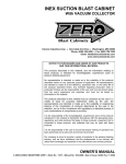
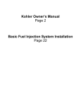
General Description: The layout and components of the Easy Load systems are shown in Figures 1
and 2. The only difference between the two systems
shown in the figures, is that one uses a 6 cubic foot storage
hopper mounted on the blast machine, while the other
uses the larger free-standing 17 cubic foot hopper. Figure
1 shows them set-up for loading, Figure 2 shows them setup for recovery of spent abrasive.
The illustrations are shown with the reverse pulse dust
collector. See Figure 4 for an illustration of the wet-filter. All
connections, regardless of the dust containment options
are the same as shown in Figures 1 and 2.
The first component, the Vacuum Producer ie., VPR, is
designed in such a way that incoming compressed air
creates a suction, giving the system its vacuum source.
The vacuum is directed, through a sealed circuit, to the
pick-up tool, where it will be used in one of two modes;
loading, and recovery.
In either mode the sealed vacuum circuit flows through one
of two dust containment options, a wet-filter drum, or the
more efficient, dry, reverse pulse dust collector. Both dust
containment options remove dust and fines, allowing only
filtered air to enter the vacuum producer where it is
exhausted through a silencer into the atmosphere.
1.4
Application
1.4.1 Dual Purpose:
loading or recovery.
All systems can be used for
1.4.2 Loading Mode: (See Figure 1) The Easy Load is
a pneumatic abrasive loader which can move new or
reusable abrasive from the loading hopper to the blast
machine storage hopper, or the pick-up tool can be removed from the loading hopper to load piled abrasive. The
system can be truck or trailer mounted for portable use or
used in a permanent facility.
"Warning" is used to indicate a potentially hazardous situation which if not avoided, could result in death or serious injury.
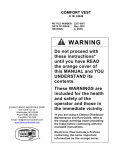
1.4.3 Recovery Mode: (See Figure 2) The pick-up tool
is removed from the loading hopper and used as a portable
pick-up tool. In this mode, spent abrasive is vacuumed
from the blasting area, to a collection container for easy
dumping.
! DANGER
Blast Nozzle CFM Chart
PSI
"Danger" is used to indicate an imminently hazardous situation which, if not avoided will result
in death or serious injury.
30
40
50
Nozzle Size
1/4"
5/16"
3/8"
7/16"
1/2"
60
70
80
90
100
68
113
161
217
280
74
126
173
240
309
81
137
196
254
338
CFM
33
53
72
101
137
40
65
90
124
166
47
77
108
147
195
54
89
126
170
224
61
101
143
194
252
EASY LOAD
Inlet
Page 2
Outlet
Inlet
Outlet
Dust Collector or
Wet Filter
Blast Machine
Storage Hopper
Loading Hopper for
New Abrasive
Vacuum Producer
(VPR)
Air Connection
Reusable Abrasive
Pick-up Tool
Disposal Bag
(optional)
Inlet
Outlet
17 cu ft Hopper
Flapper Valve
The inlet elbow has a long
tube, the outlet elbow has a
short tube.
Figure 1.
2.0
AIR REQUIREMENTS
3.0 SET-UP
2.1
Vacuum Producer
3.1 Set-up Notes
2.1.1 The vacuum producer (VPR) requires 290 cfm at
100 psi. The optional reverse pulse dust collector requires
10 cfm at 90 psi. The compressor must be large enough to
maintain 90-100 psi at the VPR, or maintain the required
pressure at the nozzle, as specified in the Blast Nozzle
CFM Chart. If the VPR, blast machine, and dust collector
are to be used at the same time, the compressor must be
large enough to maintain all pieces of equipment, plus the
additional cfm required by other tools.
2.2
Air Supply Hose
2.2.1 Recommended air supply hose is 1-1/2" I.D. or
larger. The vacuum producer connection is 1-1/2" npt.
3.1.1 The following text explains the set-up for using the
Easy Load in the loading mode. Set-up for recovery is the
same except a recovery container is used in place of the
blast machine storage hopper. If the 17 cubic foot hopper
is used the only difference is the blast machine is removed
from under the hopper and replaced with a disposal drum.
See Figure 1 for loading set-up, Figure 2 for recovery setup.
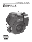
3.1.2 The illustrations in Figures 1 and 2 shows the
optional reverse pulse dust collector. Set-up for the wetfilter is the same as the dust collector with the exceptions
noted in section 3.6.1. See Figure 3 for wet-filter illustration.
EASY LOAD
Page 3
Expendable Bulk Abrasive
Collection
Container
(Precleaner)
Optional
Inlet
Outlet
The inlet elbow has a long
tube, the outlet elbow has a
short tube.
55 Gallon Drum
3.2
Set-Up (Refer to Fig. 1 and 2).
3.2.1
Position all components in a convenient location.
!WARNING
The blast machine and storage hopper must be
assembled and used on a flat, level surface. The
blast machine and hopper must be adequately
supported to ensure stability when the hopper is
loaded with abrasive.
3.3
Six Cubic Foot Storage Hopper Assembly
NOTE: An umbrella must be installed over the blast machine pop-up opening for this application. If an umbrella is
not installed, the weight of the abrasive will prevent the
pop-up valve from closing.
Figure 2.
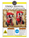
3.3.1 Attach the mounting clamps to the blast machine
as shown in Figure 3. The top of the clamps should be
approximately 2" to 3" from the top of the machine. Consideration must be given to where the access door should be
located, before securing the mounting clamps.
3.3.2 Place the rubber U-channel extrusion over the rim
of the blast machine. To obtain an air tight seal, the ends
of the extrusion must be square cut and tightly compressed. Rubber adhesive will help hold the extrusion in
place during assembly.
3.3.3 Lower the 6 cubic foot storage hopper onto the
blast machine. Align it by guiding the mounting clamp
eyebolts into the holes on the hopper tabs. Secure all nuts
and bolts.
EASY LOAD
3/8 NC Nut
Page 4
3.4.2 Mount the empty 17 cu. ft. storage hopper onto the
frame, and adjust frame to required height.
Storage Hopper
Flatwasher
Hopper Tabs
Umbrella
Rubber U Channel
3/8 NC Nut
3.4.3 Place the lid assembly on the 17 cu. ft. hopper.
The elbow with the long dip tube is the inlet. Verify the “IN”
label is at the elbow with the long tube.
3.4.4 Place the blast machine or collection container
under the flapper valve assembly. The blast machine or
container must be filled manually by opening the flapper
valve.
3.5
Position Loading Hopper
Blast Machine
Lockwasher
Flatwasher
Eyebolt
Mounting Clamp (2)
3/8 NC Cap Screw
Figure 3.
! WARNING
Do not work under the hopper while it is hanging
from a lifting devise. Severe injury can occur if
the hopper is released from the lifting device
before it is secured to the blast machine.
3.3.4 Place the lid assembly on the storage hopper.
(When using the system in the recovery mode, use the lid
over a collection container, see Figure 2). The elbow with
the long dip tube is the inlet. Verify that the “IN” label is at
the elbow with the long tube.
3.4
Seventeen Cubic Foot Hopper Assembly
3.5.1 The hopper may be mounted in the cube frame at
ground level or recessed to be level with the floor. The
recessed mounting requires a 22-1/4" square hole cut into
the floor. The hopper is set into the hole, and is supported
by the hopper flange.
NOTE: Recessed mounting requires 22" free space below
the floor, and be accessible to install and adjust the bulk
pick-up tool.
3.6
Assemble Dust Containers
3.6.1 Wet-filter, Figure 4: for assembly of the reverse
pulse dust collector see section 3.6.2.
Inlet
(from Storage
Hopper Outlet)
Outlet
To VPR Inlet
Water Level
! WARNING
Do not lift the storage unit, or adjust the hopper
height if the hopper contains abrasive. Lifting
lugs are NOT designed to lift the weight of the
hopper with abrasive. Do not work under the
hopper while it is hanging from a lifting devise.
Severe injury can occur if the hopper is released
from the lifting device before it is secured to all
supporting legs.
3.4.1 Mount the legs onto the triangular frame by aligning the holes in the legs with those in the frame, inserting
quick release pins to secure. Adjust to approximate height.
Figure 4.
3.6.1.1 Fill the wet-filter drum with water until approximately 1/3 full. The wet-filter drum must have enough
water in it to contain dust. During operation, if excessive
water comes from the VPR silencer, reduce the water
level. If excessive dust is emitted, increase the water level.
Small amounts of dust and water are normal. If conditions
will not allow discharge from the VPR, the system can be
up-graded to a reverse pulse collector.
EASY LOAD
3.6.1.2 Attach the lid to the filter. The elbow with the long
dip tube is the inlet. Verify the “IN” label is at the elbow with
the long tube. Skip to section 3.7
3.6.2
Reverse Pulse Dust Collector
Figure 5
Diaphragm Valve
Manifold
Page 5
3.6.2.4 Open the panel to verify the following connections: Connect an air line between the “Low pressure” side
of the differential pressure gauge to the upper fitting on the
collector wall. Connect another line from the “High pressure” side of the gauge to the 1/4" air filter on the collector
wall. See Figure 6 for air schematic.
Manifold
Outlet
Drain Petcock
Low
pressure
(clean side)
Low pressure
side
Diaphragm Valve
Inlet
High
pressure
(dirty side)
Differential
Pressure Gauge
Air Filter
(high pressure
side)
Air Inlet
Differential
Gauge
Filter/Regulator
1/4" Air Filter
High
Pressure
Timer Panel
Air Supply
Low
Pressure
OUTPUT
CYL
OUTPUT
SUPPLY
VOLUME
IN
Off Timer
Pulse
Control Valve
On Timer
Pulse Control
Valve
Figure 6.
Dump-out Valve
3.6.2.5 Close the dump-out valve.
3.6.2.6 Place a dust disposal drum under the collector
dump-out valve, or attach an optional disposal bag to the
dump-out pipe.
Disposal Bag
(optional)
3.7
Figure 5.
3.6.2.1 Attach the dust collector lid assembly to the collector housing. To ensure the pulse jets are positioned
correctly, the lid has two locator bolts that must be aligned
with holes on the body before clamping the latches.
3.6.2.2 Install an air fitting on the timer panel filter/regulator, and attach a 1/2" or larger air hose.
3.6.2.3 Connect air lines between the quick release diaphragm valves and panel fittings as shown in Figure 6.
Vacuum Hose Connections
3.7.1 Attach one 3" x 10 ft. connecting hose to the
vacuum producer by twisting the hose clockwise over the
casting stub. The other end is attached to the outlet of the
wet-filter or dust collector. Secure both ends with worm
clamps.
3.7.2 Attach the other 3" x 10 ft. connecting hose between the storage hopper outlet, and the wet-filter or dust
collector inlet. Secure with worm clamps.
3.7.3 Attach the uncoupled end of the 25 ft. pick-up hose
to the storage hopper inlet. Do not connect the other end
to the pick-up tool at this time.
EASY LOAD
3.8
Vacuum Producer (VPR)
3.8.1 Attach a 1-1/2" I.D. or larger air hose from the
compressor to the inlet valve of the vacuum producer. The
vacuum producer inlet valve is 1-1/2" NPT.
4.0
OPERATION
NOTE: Operating vacuum is usually between 4" to 8"
Mercury (Hg). Lower vacuum normally indicates a leak or
the pick-up tool adjustment holes are open too far. Higher
vacuum usually indicates not enough air enters the tool.
Some applications may obtain better conveying rates with
lower or higher than normal vacuum. Best conveying rates
will be achieved by monitoring the vacuum gauge and air/
abrasive mixture.
4.1
Common for loading and recovery
4.1.1
Close the vacuum producer inlet valve.
4.1.2 Check that all access doors are closed and secure
including; lids, flapper valve (17 cu. ft. hopper only) or
dump-out valve (dust collector only).
4.1.3 Start the compressor and bring it to operating
conditions.
4.1.4 Slowly open the compressor’s main air valve, to
pressurize the air lines to the VPR, and dust collector (dust
collector models only).
!NOTICE
New dust collectors and cartridges should not be
pulsed until cartridges are seasoned, see section
6.2.6.
4.1.5 Switch the pulse control valve, located on the timer
panel cover, to on.
4.1.6 Open the inlet valve on the vacuum producer,
operation will begin immediately.
Page 6
4.1.7 Check the VPR pressure gauge. Optimum pressure is 90-100 psi.
4.1.8 Check the pulse pressure (dust collector models
only). Pressure should be 90-100 psi.
4.1.9 Check the vacuum system for leaks by blocking
approximately 90% of the pick-up end of the pick-up
conveying hose with a board or other solid, flat object.
Listen to, and feel each hose connection and seal between
each segment for leaks. If leaks are found at hose connection, tighten the clamps. If there are leaks between segments, check the gaskets and clamp tension.
! CAUTION
Never completely block off the vacuum air inlet.
Damage to drums, hoppers, or hoses may occur
due to the high vacuum produced. Shut-down
immediately if vacuum exceeds 20" Hg.
4.1.10 Turn off the vacuum producer by closing the air
valve. Attach the pick-up tool to the coupled end of the
pick-up conveying hose.
4.1.11 The tool may now be put into the loading hopper,
for operation in the loading mode, or it can be hand held for
abrasive recovery.
4.2
Loading Mode
4.2.1
Place the pick-up tool into the loading hopper.
4.2.2 Remove the cover from the loading hopper, drop
bagged abrasive onto the screen and bag opener. Tear the
punctured bag open, permitting abrasive to fall into the
hopper.
4.2.3 Start the loading process by opening the air valve
on the vacuum producer.
4.2.4 Adjust the air intake on the pick-up tool as described in section 5.1.
!WARNING
4.2.5 Continue to fill the loading hopper until the blast
machine and/or storage hopper is full. DO NOT OVER
FILL. Abrasive flow will slow down noticeably when hoppers are full.
Ear protection is required when the vacuum producer is in operation.
4.2.6 As hoppers become full, stop filling the loading
hopper and allow the pick-up hose to clear.
EASY LOAD
4.2.7 Shut-down the vacuum producer by closing the air
inlet valve.
4.3
4.3.2 The bulk pick-up tool is used for moving heavy
concentrations of abrasive from the storage hopper, drums,
or abrasive piles. Optional tools are available. They are
listed under accessories and below for suggested use.
•
Crevice Tool: used for vacuuming narrow recessed
areas.
*
Flare Tool: used to vacuum thin layers or spread out
layers of abrasive on flat areas such as floors.
Wall Brush: used for vacuuming dust from walls and
floors.
4.3.3 As the collection containers become full, the recovery rate will noticeably decrease. At that point, stop
recovery and allow pick-up hose to clear.
4.3.4 Shut-down the system to empty or replace the
collection container and dust collector. Continue with the
recovery until the blast area is clean.
4.4
ADJUSTMENTS
5.1
Pick-up Tool
5.1.1 Adjust the air intake on the pick-up tool by sliding
the bell shaped collar back from the outer pick-up tube.
The further the collar is moved, the more air will be drawn
in. Further adjustment may be made by moving the collar
off of the air intake holes. Open only as far as needed to
keep the abrasive flowing. Too much air will decrease
recovery rates. Too little air will cause abrasive to pack,
which will also decrease rates.
5.2
Latches
5.2.1 Loosen the lock nut, and turn the latch hook in or
out as required to pull the segment tight when the hook is
latched.
5.2.2
Tighten the lock nut.
5.3
Inlet/Outlet Elbows
5.3.1
Loosen the nuts on the U-clamp.
5.3.2 Rotate the elbows to the best position to facilitate
vacuum hose connections.
5.3.3 Be certain the slits in the elbow slides below the
end of stub.
5.3.4
Tighten the U clamps to secure.
5.4
Pulse Pressure (dust collector models only)
Shut-down
NOTE: Do not recover and load any-more abrasive than
will be used. Condensation may develop in the hopper and
blast machine, which will cause abrasive to get damp.
Abrasive should be stored in air tight containers at the end
of the work day.
4.4.1 Stop recovery and let abrasive clear from all
recovery hoses.
4.4.2 Shut-down the vacuum producer by closing the air
inlet valve.
4.4.3 Turn off the pulse control valve, and drain the
manifold tank (dust collector models only).
4.4.4
5.0
Recovery
4.3.1 Hold the handle of the pick-up tool in one hand.
The other hand is used to help maneuver the tool to the
most comfortable position for the operator. The pick-up
hose is usually placed over the opposite shoulder or under
the opposite arm, depending upon the angle at which the
tool will be used.
•
Page 7
Empty dust containers, precleaner, and hopper.
5.4.1 Pulse pressure is adjusted by the filter regulator
combination located on the timer panel inlet. Adjust pressure between 90 psi and 100 psi.
5.5
Pulse Timer
(Refer to the air schematic in Figure 6,
dust collector models only)
5.5.1 The timers are located in the timer panel. Open
the panel door and adjust as follows:
5.5.2 Turn on the air supply, and switch the pulse
control valve to on.
5.5.3
Turn both timer knobs fully clockwise to close.
5.5.4 "ON" time (lower timer) “On” time is the length of
each pulse. The pulse should be kept as short as possible,
because it is the initial burst of air that cleans the cartridge.
Adjust the “On” time by turning the knob three full turns
counterclockwise.
Page 8
EASY LOAD
5.5.5 "OFF" time (upper timer) “Off” time is the time
between each pulse. Adjust the off time by turning the knob
approximately one half turn counterclockwise until the
time between each pulse is around 15 seconds.
5.5.6 The differential pressure gauge is useful in determining the need to change the time between pulses ("off'
time). When the gauge consistently reads 6" or above,
(reading taken with the VPR on, and no recovery) turn the
"OFF" time (upper timer) knob counterclockwise to increase the pulses, and lower the reading.
6.2
! WARNING
NIOSH approved air-supplied respirators and protective clothing must be worn when servicing any
area of the system and collector that exposes the
user to dust.
6.2.1
6.0
MAINTENANCE
6.1
Preventive Maintenance
6.1.1 Never operate without the pick-up tool. Using a
hose without a pick-up tool to vacuum, will usually decrease recovery rates.
6.1.2 Do not leave abrasive in storage hopper, blast
machine, or loading hopper overnight. Condensation may
develop in the hopper, which will cause abrasive to get
damp. At the end of the work day abrasive should be stored
in air tight containers.
6.1.3 Do not over fill the system. Production decreases
noticeably once the abrasive level reaches the bottom of
the inlet tubes on the hopper cover. This will also cause
carry over of useable abrasive into the dust container.
General Maintenance
Check and clean storage hopper screens daily.
6.2.2 Empty dust filters and precleaner at least daily.
Loading dusty abrasive, or recovering spent abrasive will
require more frequent emptying.
6.2.3 Immediately check filter cartridges for damage if
dust is emitted from the vacuum producer silencer.
6.2.4
Emptying dust collector
6.2.4.1 Shut off the VPR, turn off the pulse control valve,
and drain the manifold tank.
6.2.4.2 Check that the dust disposal container or bag is in
place and sealed around the dump-out opening.
6.2.4.3 Open the dump-out valve to let dust enter the
disposal container.
6.1.4 Do not operate without the dust collector, or wetfilter drum. Doing so will cause premature wear on the
vacuum producer and silencer, and excessive dust.
! CAUTION
6.1.5 Shut-down immediately if sand or dust is seen
coming from the vacuum producer silencer. Check the
filter cartridges or water level.
To avoid spilling harmful dust, close the dumpout valve before the dust container is full. The
container must have the capacity to hold dust left
in the tube after the valve is closed.
6.1.6 Keep all hose as straight as possible. Bends in the
hose will accelerate wear and also decrease efficiency.
6.1.7 Do not pulse the dust collector with the dump-out
valve open. Doing so will cause dust leaks every time the
collector pulses.
6.1.8 Do not operate with the dust collector dump-out
valve open. Doing so will loose vacuum and cause pneumatic wear of dump-out valve and other parts.
6.1.9 Drain the dust collector pulse manifold at the end
of daily operations. Drain more frequently if water is
present in the air line. A drain petcock is located on the
bottom of the manifold.
6.2.5
Changing filter cartridges.
6.2.5.1 Empty dust collector.
6.2.5.2 Remove the vacuum hose and manifold air hose
from the dust collector lid.
6.2.5.3 Remove the lid from the dust collector body.
6.2.5.4 Remove the four hex nuts and hold-down plate on
each cartridge.
Page 9
EASY LOAD
6.2.5.5 Pry up on the cartridge flange to break the seal on
the cartridge gasket. Pull the filter cartridges straight up out
of the collector housing.
6.2.5.6 Clean the top side of the cartridge plate, particularly around the sealing area.
6.2.5.7 Set the new cartridges in place, and replace the
hold-down plates. Secure with the hex nuts.
6.2.5.8 Replace the lid assembly. The lid has two locator
bolts that must be aligned with holes on the housing before
clamping the latches.
6.2.5.9 Replace the vacuum hose and manifold air hose.
7.1.9 Blockage in pick-up hose. Remove pick-up tool
and clear.
7.1.10 Flapper valve is open (17 cubic foot hopper only).
Close.
7.2
If the abrasive flow at the pick-up tool stops for a
few seconds then re-starts, check the following:
7.2.1 Air intake on pick-up tool isn’t open far enough.
Refer to section 5.1 for adjustment.
7.3
If dust or abrasive is coming from the vacuum
producer, check the following:
6.2.5.10 Season the cartridges per section 6.2.6.
7.3.1 Damaged or loose filter, shut-down and check
immediately.
6.2.6
7.3.2
Seasoning Cartridges
6.2.6.1 New cartridges must be seasoned. Cartridges are
seasoned by letting a dust cake develop on the filter media
before starting the pulse cycle.
6.2.6.2 Let new cartridges run without pulsing (pulse
control valve turned off) until the differential pressure
gauge reads 1 inch above the initial reading. At that point
the pulse control valve can be turned on to start the pulsing
cycle. New dust collectors and cartridges should not be
pulsed until cartridges are seasoned.
7.4
If there is excessive water coming from the vacuum
producer silencer (wet-filter only), check the following:
7.4.1
7.1
Water level in the wet filter is too high.
NOTE: A small amount of water coming from the
silencer is normal. As dust is collected in the drum, the
water level will rise and carry over to the vacuum
producer.
7.5
7.0 TROUBLESHOOTING
Water level in wet-filter is not high enough.
Carry over of useable abrasive to dust container.
7.5.1 Blast machine or storage container full. Decrease
loading time.
No vacuum or low vacuum at the pick-up tool.
7.1.1 Clogged filter cartridges. Decrease pulse time or
replace cartridges.
7.1.2 Leak in hose connections, storage hopper or filter
lids. See Section 4.7.
7.1.3 Access door in storage hopper is open or leaking.
Close, repair or replace gasket.
7.1.4 Inadequate air supply. Check pressure gauge on
vacuum producer. It should be between 90-100 psi.
7.1.5 Worn venturi tube insert in vacuum producer.
Replace.
7.1.6
Venturi insert loose. Check and tighten.
7.1.7
Dirt accumulated on VPR jet. Clean.
7.1.8
level.
Storage hopper or dust container is full. Check
7.5.2 Inlet and outlet hose reversed on the storage
hopper. The elbow with the long dip tube is the inlet, see
Figure 1. Verify that the pick-up hose is connected to the
elbow with the long tube.
8.0
ACCESSORIES
(Optional)
Description
Stock No.
Bulk pick-up tool, 2" O.D ....................................... 04327
Crevice tool, 2" O.D. with swivel adaptor
and coupling ............................................. 04270
Crevice tool, 3" O.D. with swivel adaptor
and coupling ............................................. 04271
Flare tool, 2" O.D. with swivel adaptor
and coupling ............................................. 04272
Flare tool, 3" O.D. with swivel adaptor
and coupling ............................................. 04273
Wall brush assembly, 2" ....................................... 04300
Hose, 2" bulk vacuum, up to 100 ft.
(specify length in feet) .............................. 10332
EASY LOAD
Hose, 3" bulk vacuum, up to 100 ft.
(specify length in feet) .............................. 10286
3"-2" Vacuum hose transition,
connects 2" vacuum hose to 3" hose ...... 11221
Page 10
NOTE: To connect two 3" hoses together, it is necessary to order:
2
Hose end coupler 3" ................................ 04338
2
Clamp, 3" hose ........................................ 02816
1
Clamp, 3" coupler .................................... 08777
(5)
(10)
(6)
(9)
(10)
(3)
(1)
(2)
(4)
(11)
(10)
(13)
(12)
(5)
(5)
(8)
(7)
Figure 7.
9.0
REPLACEMENT PARTS
9.1
System Replacement Parts,
Figure 7
Item
1.
2.
3.
4.
Description
Stock No.
290 Vacuum producer with silencer ........ 07585
Attachment kit, 24" blast machine ........... 10289
Loading hopper ........................................ 07556
Pick-up tool, 3" bulk ................................. 04275
5.
6.
7.
8.
9.
10.
11.
12.
13.
Lid assembly,
with 3" inlet ........................................ 20417
with 2" inlet (for CCB) ........................ 20419
Hopper assembly, 6 cu.ft. ........................ 07568
Hopper assembly, 17 cu.ft ....................... 10793
Precleaner/wet-filter drum ........................ 20418
Dust collector, complete .......................... 20416
Hose, 3" x 10 ft vacuum ........................... 10900
Hose, 3" x 25 ft vacuum ........................... 10902
Hose end coupler, 3" ............................... 04338
Clamp, 3" hose ........................................ 02816
EASY LOAD
(7)
(8)
(1)
(9)
(10)
(11)
(5)
(2)
(3)
(12)
(13)
(6)
(4)
Figure 8.
Page 11
9.2
Storage Hopper, 6 Cubic Foot
Figure 8
Item
Description
(-)
1.
2.
3.
4.
Stock No.
Storage hopper, complete ....................... 07568
Storage hopper weldment ........................ 07548
Door ......................................................... 07560
Latch assy, spring, door ........................... 12263
Gasket, 7/16" x 1" adhesive backed,
7 ft. required ...................................... 00190
Gasket, door ............................................ 11745
Screen ...................................................... 15091
Latch assy, hook ...................................... 20445
Screw, 1/4-nc x 1 hex head. .................... 03053
Nut, 1/4-nc hex ......................................... 03111
Washer, 1/4" lock ..................................... 03117
Washer, 1/4" flat ...................................... 03116
Screw, 10-32 x 1/2" truss ......................... 12062
Nut, 10-32 lock ......................................... 12731
5.
6.
7.
8.
9.
10.
11.
12.
13.
(11)
(2)
9.3
Hopper Assembly, 17 Cubic Foot
Figure 9
Item
Description
(-)
1.
2.
3.
4.
5.
6.
7.
8.
9.
10.
11.
Hopper assembly, complete .................... 10793
Hopper only, 17 cu. ft. .............................. 07579
Volume segment ...................................... 07547
Stand assembly ....................................... 07559
Release pin and chain ............................. 10276
Hinge (rubber), flapper valve ................... 04062
Gasket, flapper valve ............................... 04061
Clamp, flapper valve ................................ 10186
Tee bolt, flapper valve ............................. 10187
Counter weight, flapper valve .................. 04065
Clamp, flapper valve hinge ...................... 04057
Latch assy., hook ..................................... 20445
Stock No.
(1)
(4)
(3)
(7)
(5, 10)
(6)
(9)
(8)
Figure 9.
Page 12
EASY LOAD
(4)
9.4
Loading Hopper Assembly
Figure 10
Item
Description
(3)
(1)
(5)
(2)
(6)
(7, 8, 9)
(-)
1.
2.
3.
4.
5.
6.
7.
8.
9.
Stock No.
Loading hopper, complete ....................... 07556
Hopper ..................................................... 07567
Frame ....................................................... 07532
Screen ...................................................... 10293
Cover........................................................ 10294
Retainer, gasket ....................................... 07533
Gasket ...................................................... 07534
Screw, 1/4-nc x 1/2" hex head ................. 03051
Nut, 1/4-nc ............................................... 03111
Washer, 1/4" flat ...................................... 03116
Figure 10.
9.5
Lid, Cover Assembly
Figure 11
(3, 4)
(4)
Item
Description
Stock No.
(-)
(-)
1.
2.
3.
4.
5.
6.
7.
8.
9.
10.
11.
12.
Lid assembly, complete, with 3" inlet ....... 20417
Lid assembly, complete, with 2" inlet ....... 20419
Lid weldment ............................................ 20414
Retainer quadrant, each .......................... 20395
Elbow, 2" .................................................. 10792
Elbow, 3" .................................................. 10179
Gauge, 30" Hg vacuum ............................ 10169
Gasket, dip tube ....................................... 10232
Gasket, extruded...................................... 20443
3" Outlet tube, 3.5" long ........................... 10451
3" Inlet tube, 8.5" long .............................. 10452
2" Inlet tube, 8.5" long .............................. 10790
2" U-clamp ............................................... 10789
3" U-clamp ............................................... 10486
(11, 12)
(5)
(6)
(8)
(7)
(2)
(1)
(9, 10)
Figure 11.
9.6
Precleaner Drum
Figure 12
Item
Description
(1)
(-)
1.
2.
3.
4.
5.
(2, 3, 4, 5)
Figure 12.
Stock No.
Precleaner drum, complete ...................... 20418
Latch assembly, hook .............................. 20445
Screw, 1/4-nc x 1 hex head ..................... 03053
Nut, 1/4-nc hex head ............................... 03111
Washer, 1/4" lock ..................................... 03117
Washer, 1/4" flat ...................................... 03116
EASY LOAD
9.7
Vacuum Producer
Figure 13
Item
Description
(-)
(-)
1.
2.
3.
4.
5.
6.
7.
8.
9.
10.
11.
Stock No.
VPR assembly complete .......................... 07585
VPR assembly without silencer ............... 07599
Silencer .................................................... 07594
Venturi tube .............................................. 07544
(5)
(10)
(9)
Page 13
Screw, 1/4-nc x 1/4" set ........................... 03075
Jet, air VPR-290 ....................................... 07516
Body ......................................................... 07524
Adaptor, air jet, 290 ................................. 07598
Gasket ...................................................... 07514
Nipple, 1-1/2" x 10" .................................. 07531
Gauge, pressure ...................................... 07520
Valve, 1-1/2" npt ball ................................ 07596
Insert, 290 venturi .................................... 10912
(4)
(6)
(3)
(1)
(11)
(2)
(8)
(7)
Figure 13.
9.8
Item
(-)
1.
2.
3.
4.
5.
6.
7.
8.
9.
10.
11.
12.
13.
14.
15.
16.
17.
(4) (3)
Dust Collector
Figure 14
Description
(9)
(10)
(7)
(12)
(8)
Stock No.
Dust Collector, Complete ......................... 20416
Valve, 1" diaphragm ................................. 10392
Filter cartridge .......................................... 20444
Gauge, 30" Hg vacuum ............................ 10169
Elbow, 3" .................................................. 10179
3" U-clamp ............................................... 10486
Latch assy, hook ...................................... 20445
Petcock .................................................... 01993
U-channel, rubber, 7 feet required ........... 04076
3" Outlet tube, 3.5" long ........................... 10451
Gasket, dip tube ....................................... 10232
Filter regulator 1/2" .................................. 20442
Lid weldment ............................................ 20414
Valve, 6" dump ......................................... 21082
Pipe, 6" outlet ........................................... 20459
Bag, 4 cu ft dust ....................................... 21083
Clamp ....................................................... 11576
Gasket, dump valve, 2 required ............... 20204
(1)
(6)
(5)
(4)
(11)
(2)
(13)
(17)
(14)
(16)
(15)
Figure 14.
EASY LOAD
Page 14
15.
16.
17.
18.
19.
20.
21.
22.
23.
24.
25.
26.
27.
28.
29.
30.
31.
32.
33.
Adaptor, elbow, 1/8" npt x 1/8" barb ........ 11733
Tubing, 1/8" urethane .............................. 12475
Actuator, air pilot ...................................... 19123
Valve, 3 way ............................................. 12202
Elbow, 1/8" npt st ..................................... 03993
Nipple, 1/8" npt hex .................................. 01962
Adaptor, 1/8" npt ...................................... 01940
Adaptor, 1/4" npt ...................................... 02494
Hose, 3/16" x 18" ..................................... 02454
Hose, 3/16" x 12" ..................................... 20440
Hose, 3/16" x 36" ..................................... 02498
Subplate, pulse timer ............................... 20446
Control, air timer ...................................... 20447
Valve, air timer ......................................... 20448
Valve, air timer ......................................... 20449
Valve, air timer ......................................... 20450
Timing chamber ....................................... 20424
Filter, 1/4" ................................................. 20438
Filter regulator .......................................... 20442
9.8
Dust Collector Air Schematic,
Figure 15
Item
Description
1.
2.
3.
4.
5.
6.
7.
8.
9.
10.
11.
12.
13.
14.
Fitting, 1/4" bulkhead ............................... 05605
Differential pressure gauge ...................... 10188
Valve, 3 way toggle .................................. 07658
Fitting, 1/8" bulkhead ............................... 20114
Tee, 1/2" npt ............................................ 01787
Nipple, 1/2" npt x close ............................ 01733
Bushing, 1/2" x 1/4" ................................. 01801
Bushing, 1/4" x 1/8" ................................. 02010
Nipple, 1/4" npt x close ............................ 01829
Hose, 1/2" air,4' req. ................................ 12472
Hose end, 1/2" swivel .............................. 15002
Adaptor, 1/2" npt x 1/2" flare .................... 11351
Valve, 1" diaphragm ................................. 10392
Adaptor, 1/8" npt x 1/8" barb.................... 11732
Stock No.
(21) (17) (18)
(19)
(20)
(12) (11)
(13)
(13)
(22)
(23)
(10)
(22)
(25)
(9)
(24)
(32)
(21)
(16) (14)
(11)
(4)
(15)
(8)
(2)
(12)
(9)
(33)
(15)
(7)
(1) (5) (6)
(15)
OUTPUT
CYL
OUTPUT
SUPPLY
VOLUME
(31)
(14)
(26)
IN
(16)
(27)
(27)
(3)
(14)
(16) (30) (28)
(29)
Figure 15.