1
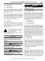
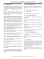
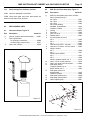
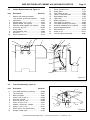
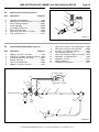
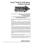
INEX SUCTION BLAST CABINET
With VACUUM COLLECTOR
Clemco Industries Corp. • One Cable Car Drive • Washington, MO 63090
Phone: (636) 239-4300 • Fax: (800) 726-7559
Email: [email protected]
www.clemcoindustries.com
NOTICE TO PURCHASERS AND USERS OF OUR PRODUCTS
AND THIS INFORMATIONAL MATERIAL
The products described in this material, and the information relating to
those products, is intended for knowledgeable, experienced users of
abrasive blasting equipment.
No representation is intended or made as to the suitability of the products
described herein for any particular purpose of application. No representations
are intended or made as to the efficiency, production rate, or the useful life of
the products described herein. Any estimate regarding production rates or
production finishes are the responsibility of the user and must be derived solely
from the user’s experience and expertise, and must not be based on
information in this material.
The products described in this material may be combined by the user in a
variety of ways for purposes determined solely by the user. No
representations are intended or made as to the suitability or engineering
balance of the combination of products determined by the user in his
selection, nor as to the compliance with regulations or standard practice of
such combinations of components or products.
It is the responsibility of the knowledgeable, experienced users of the products
mentioned in this material to familiarize themselves with the appropriate laws,
regulations and safe practices that apply to these products, equipment that is
connected to these products, and materials that may be used with these
products.
It is the responsibility of the user to insure that proper training of operators has
been performed and a safe work environment is provided.
Our company is proud to provide a variety of products to the abrasive blasting
industry, and we have confidence that the professionals in our industry will
utilize their knowledge and expertise in the safe efficient use of these products.
OWNER’S MANUAL
© 2006 CLEMCO INDUSTRIES CORP. • Stock No.: 11217 • Manual No.: 833-0288 • Date of Issue: 02/88, Rev. F, 05/06
INEX SUCTION BLAST CABINET with VACUUM COLLECTOR
1.0
INTRODUCTION
1.1
Scope of Manual
1.1.1 These instructions cover set-up, operation,
maintenance, troubleshooting, optional accessories, and
replacement parts for INEX series suction blast cabinets
with vacuum dust collector.
1.1.2 These instructions also contain important
information required for safe operation of the cabinet.
Before using this equipment, all personnel associated
with the blast cabinet operation must read this entire
manual, and all accessory manuals to become familiar
with the operation, parts and terminology.
1.2
Page 1
DANGER
Danger indicates an imminently hazardous
situation which, if not avoided, will result in
death or serious injury.
1.3
General Description
1.3.1 See Figure 1 for arrangement of components.
INEX blast cabinets enclose the blasting environment to
provide efficient blast cleaning while maintaining a clean
surrounding work area. Production rates are influenced
by size of nozzle, compressor output, working pressure,
type and size of media, angle and distance of the nozzle
from the blast surface. INEX cabinets consist of two
major components:
1. Cabinet Enclosure
2. Vacuum Collector
Safety Alerts
1.2.1 Clemco uses safety alert signal words, based on
ANSI Z535.4-1998, to alert the user of a potentially
hazardous situation that may be encountered while
operating this equipment. ANSI's definitions of the signal
words are as follows:
This is the safety alert symbol. It is used to
alert the user of this equipment of potential
personal injury hazards.
Obey all safety messages that follow this symbol to
avoid possible injury or death.
CAUTION
Caution used without the safety alert symbol
indicates a potentially hazardous situation
which, if not avoided, may result in property
damage.
CAUTION
Caution indicates a potentially hazardous
situation which, if not avoided, may result in
minor or moderate injury.
1.4
1.4.1 When the air supply is on, and the cabinet doors
are closed, the cabinet is ready for operation by actuation
of the foot pedal. Fully depressing the foot pedal causes air
to flow through the blast gun. Air moving through the gun
draws media into the blast gun mixing chamber. The
media mixes with the air and is propelled out the nozzle.
After striking the object being blasted, the heavier,
reusable blast media, falls through the mesh work table,
and into the cabinet hopper for reuse. Lighter weight dust
and fines that would normally remain suspended, are
drawn through the vacuum dust collector, which traps the
dust and discharges clean air. When the foot pedal is
released, blasting stops.
1.5
Warning indicates a potentially hazardous
situation which, if not avoided, could result in
death or serious injury.
Nozzle Options
1.5.1 Unless otherwise specified at the time of order,
cabinets are shipped with a 5/16" orifice ceramic nozzle
and No. 5 (5/32" orifice) air jet. Optional more durable
tungsten carbide and boron carbide nozzles are
available and are shown under Accessories and
Replacement Parts in Section 8.2. Use boron carbide
nozzles when blasting with aggressive media, such as
aluminum oxide and silicon carbide.
1.6
WARNING
Theory of Operation
Media
1.6.1 INEX Suction Blast Cabinets utilize most
common reusable media 25 mesh to 100 mesh, that is
specifically manufactured for dry blasting. Several
factors affecting the usable media size range are: nozzle
orifice size, air pressure, media/air mixture, media
friability, contamination of parts being cleaned, and
humidity. Media sizes noted are intended as guidelines
© 2006 CLEMCO INDUSTRIES CORP. • www.clemcoindustries.com • Manual No. 11217
INEX SUCTION BLAST CABINET with VACUUM COLLECTOR
Page 2
On-Off Switch
Air Inlet Duct
BNP Blast Gun
Vacuum
Collector
Pressure Gauge
Pilot Regulator
Metering Valve
Air Filter
Compressed air inlet
Grounding Lug
Foot Pedal
only, and are based on standard 5/16″ orifice nozzle
(5/32″ air jet) and average conditions. As a rule, larger
nozzles deliver more media, thus demand greater air
movement though the cabinet. With larger nozzles, the
maximum size of media decreases from those
recommended. Media finer than those recommended
may decrease visibility.
Figure 1
blasting pressure. Unless specified otherwise, cabinets
are supplied with a No. 5 (5/32" orifice) jet. See table in
Figure 2 to determine cfm requirements. Consult with a
compressor supplier for suggested compressor size
based on the air consumption.
BNP Gun
No. 4
No. 5
No. 6
1.6.2 Steel: Fine steel grit or shot may be used.
However, care must be taken to prevent ricocheting
abrasive from peening the cabinet weldment.
1.6.3 Sand and Slag: Sand should never be used
because of the respiratory hazards associated with
media containing free silica. Slags are not recommended
because they rapidly break down.
1.6.4 Silicon Carbide, Aluminum Oxide, and
Garnet: These are the most aggressive, high volume
abrasive in the blasting industry. Aggressive media such
as these may be used, but the service life will be
reduced on any equipment components which come in
contact with the abrasive. To avoid unscheduled down
time, periodically inspect the nozzle, media hose,
conveying hose, and filter for abrasive wear. Nozzles
lined with boron carbide are recommended to extend
nozzle wear life. See Section 8.2.
1.6.5 Glass Bead: Most beads are treated to ensure
free-flow operation even with moderately high humidity.
Glass beads subjected to moisture may be reused after
thorough drying and breaking up of any lumps.
1.7
Jet
1/8"
5/32"
3/16"
Nozzle
5/16"
5/16"
3/8"
CFM
21
32
47
PSI
80
80
80
Air Consumption in cfm
Figure 2
1.7.2 The air filter at the air inlet connection, reduces
condensed water from the compressed air. Its use is
especially important in areas of high humidity, or when
fine-mesh media are used. Moisture causes media to
clot and inhibits free flow through the feed assembly. If
moisture problems persist, an air dryer may be required.
1.8
Electrical Requirements
1.8.1 The system requires 120-VAC, 1-Ph, 60-Hz,
with 15 Amps service. A power cord is supplied. No
additional wiring is required.
WARNING
Do not use electrical adaptors that eliminate the
ground prong on 120-volt plugs. Doing so can
cause electric shock and equipment damage.
Compressed Air Requirements
1.7.1 The size of the compressor required to operate
the cabinet depends on the size of the air jet and
© 2006 CLEMCO INDUSTRIES CORP. • www.clemcoindustries.com • Manual No. 11217
INEX SUCTION BLAST CABINET with VACUUM COLLECTOR
Page 3
2.0
INSTALLATION
2.5
2.1
General Installation Notes
2.5.1 Plug the collector’s power cord into the socket
on the cabinet light switch box. Turning the collector
switch on will enable the light switch to control the
collector motor.
2.1.1 See Figure 1 for the general arrangement. Place
all components in a convenient location where
compressed air and electrical services are available.
The cabinet location must comply with OSHA and local
safety codes. Allow for full access to all doors and
service areas, and for efficient handling of large parts.
Determine the best location, and position all units before
final assembly.
2.2
Connect Compressed Air Supply Line
2.2.1 See the table in Figure 3 to determine the
minimum ID of air supply line to the cabinet air inlet. A
smaller diameter hose may reduce blasting efficiency.
Air Line Length
25 feet
50 feet
75 feet
100 feet
No. 4
3/4"
3/4"
3/4"
3/4"
Jet Size
No. 5
3/4"
3/4"
1"
1"
No. 6
1"
1"
1"
1"
Minimum compressed air line ID
Figure 3
2.2.2 Install an isolation valve at the air source to
enable depressurization for service, and connect the air
line from the air source to the air filter inlet located on
the inside of the cabinet skirt.
WARNING
If twist-on type air hose couplings are used,
they must be secured by safety pins or wires to
prevent accidental disconnection while under
pressure. Hose disconnection while under
pressure could cause serious injury.
2.3
Connect Conveying Hose
2.3.1 Connect flexible conveying hose between the
collector and exhaust tube, located on the outside rear
wall of the cabinet.
2.4
Final Assembly
2.5.2 Position the foot pedal on the floor at the front of
the cabinet.
2.5.3 A package of 5 cover lenses is supplied with the
cabinet. To install a cover lens, remove the adhesive
backing and apply the lens to the clean, dry, inner
surface of the view window per Section 5.3. When the
cover lens becomes pitted or frosted, replace it.
2.5.4 Plug the cabinet power cord into a grounded,
120-volt outlet.
3.0
OPERATION
3.1
Media Loading and Unloading
3.1.1 Media Loading: Pour clean dry media directly
through the crate, into the cabinet hopper. Do not load
the hopper over 1/4 full. Use less media if the parts
being blasted cause media to be quickly contaminated.
3.1.2 Media Unloading: Place an empty container
under the metering valve and unscrew the plastic plug
from the metering valve. If media doesn't flow, it has
caked. Open the cabinet door and stir media until it
starts to flow. Replace the plug when the cabinet is
empty.
3.2
Loading and Unloading Parts
WARNING
Use solid fixturing to hold heavy parts in place.
Do not remove lift equipment until the part is
adequately supported to prevent movement.
Moving heavy, unsupported parts may cause
them to shift or topple, and cause severe injury.
Ground Cabinet
2.4.1 To prevent static electricity build up, attach an
external grounded wire from an earth ground to the
grounding lug on the left rear of the cabinet.
3.2.1
Load and unload parts through either door.
3.2.2 Parts must be free of oil, water, grease, or other
contaminants that will cause media to clump, or clog the
filter.
© 2006 CLEMCO INDUSTRIES CORP. • www.clemcoindustries.com • Manual No. 11217
INEX SUCTION BLAST CABINET with VACUUM COLLECTOR
3.2.3 When blasting very small parts, place an
appropriately sized screen over the grate to prevent
parts from falling into the hopper.
3.2.4 Close door. Be certain doors are sealed
securely.
3.4.2 Allow the exhauster to clear the cabinet of
airborne dust before opening the door.
3.4.3 Unload parts, shut off the air supply valve, drain
the air filter, and switch off the lights and exhauster.
3.5
3.3
Blasting Operation
CAUTION
•
•
•
•
•
Always close cabinet doors before blasting.
Keep doors closed during blasting.
Always wear blast gloves.
Avoid pointing the blast nozzle toward the
view window.
After blasting, keep doors closed and
exhauster on until the cabinet is clear of all
airborne dust.
Stop blasting immediately if dust leaks are
detected.
3.3.1 Slowly open the air valve on the air supply hose
to the cabinet. Check for air leaks.
3.3.2 Adjust the pilot pressure regulator located under
the cabinet skirt, to the required blast pressure per
Section 4.1.
3.3.3 Turn on the lights and collector. The on/off
switch performs both functions.
3.3.4
3.3.5 Close door. Be certain doors are sealed
securely.
3.3.6
Insert hands into gloves.
3.3.7 To blast; hold the gun firmly and apply pressure
to the foot pedal; blasting will begin immediately.
3.3.8 When blasting very small parts, place an
appropriately sized screen over the grate to prevent
parts from falling into the hopper. Should an object fall
through the grate, stop blasting immediately and retrieve
it. Whenever possible avoid holding small parts that will
require blasting into the glove.
3.4
Stop Blasting
3.4.1 To stop blasting, remove pressure on the foot
pedal.
Blasting Technique
3.5.1 Blasting technique is similar to spray painting
technique. Smooth continuous strokes are most
effective. The distance from the part affects size of blast
pattern. Under normal conditions, hold the nozzle
approximately 3" to 6" from the surface of the part.
4.0
ADJUSTMENTS
4.1
Blasting Pressure
4.1.1 The pilot regulator, located under the cabinet
skirt, enables the user to adjust blasting pressure to suit
the application. The suitable pressure for most purposes
is 80 psi. Lower pressures may be used for delicate
work. In all cases, highest production can be achieved
only when pressure is carefully monitored.
4.1.2 To adjust, unlock the knob, and turn it clockwise
to increase pressure or counter-clockwise to decrease
pressure. Pressure will usually drop from closed-line
pressure when blasting is started. Once operating
pressure is set, lock the knob to maintain the setting.
4.2
Load parts.
Page 4
Air Jet Adjustment
4.2.1 The air jet should be screwed 4-1/2 to 5 full
turns into the gun body. Doing so will leave 3-1/2 to 4
threads exposed past the lock nut. Tighten the lock nut
to hold the jet in place. See Section 8.2 for optional
adjusting tool.
4.3
Media/Air Mixture, Figure 4
4.3.1 Check the media stream for correct media/air
mixture; media flow is smooth and appears as a light mist
coming from the nozzle.
4.3.2 If media does not flow smoothly, loosen the
locking nut, and adjust the metering screw until the upper
holes in the metering stem are closed-off, and the lower
holes are fully open. See Figure 4. This adjustment is a
starting point.
4.3.3 If pulsation occurs in the media hose, either media
is damp and caked, or not enough air is entering the media
stream. While blasting, loosen the locking nut and slowly
turn the adjusting screw out (counterclockwise when
© 2006 CLEMCO INDUSTRIES CORP. • www.clemcoindustries.com • Manual No. 11217
INEX SUCTION BLAST CABINET with VACUUM COLLECTOR
viewed from the top) until the media flows smoothly.
Tighten the locking nut finger-tight to maintain the setting.
Locking Nut
5.2
Lower holes fully open
Figure 4
4.3.4 If media flow is too light, decrease air in the
mixture by turning the metering screw in (clockwise when
viewed from the top) covering more of the holes so less air
enters the media hose. Tighten the locking nut finger-tight
to maintain the setting.
5.0
BNP Gun Assembly
5.1.1 Inspect the BNP gun for wear. Inspection and
replacement of the air jet cover before it wears through
will prolong the life of the jet.
Adjusting Screw
Upper holes
fully Closed
5.1.
Page 5
PREVENTIVE MAINTENANCE
WARNING
Failure to wear approved respirators and eye
protection when servicing dust-laden areas of
the cabinet and vacuum collector, and when
emptying the collector could result in serious
eye irritation and lung disease or death.
Toxicity and health risk vary with type of media
and dust generated by blasting. The respirator
must be approved for the type of dust
generated. Identify all material being removed
by blasting, and obtain a material safety data
sheet for the blast media.
NOTE: To avoid unscheduled downtime, establish a
weekly inspection schedule. Inspect all parts subjected
to media contact, including; the gun, nozzle, media
hose, and flex hose, plus all items covered in this
section.
Dust Filter
5.2.1 The filter collects dust on its outer surface. A
high dust level in the cabinet indicates a dirty filter.
Empty as frequently as necessary to maintain visibility in
the cabinet, or daily and adjust frequency based on
usage and breakdown rate of media. Dump the contents
into a suitable disposal container.
NOTE: Blast media is usually non-toxic, however, some
materials removed by the process may be. Do not use
the INEX cabinet for blasting toxic materials. Use
cabinets with reverse pulse dust collectors and HEPA
filter for those applications.
5.2.2 Clean the filter by using a low pressure air blowoff nozzle. Direct the air inside the filter, blowing toward
the outside or brush the outside of the filter with a soft
bristle brush.
5.3
View Window Cover Lens
5.3.1 Rapid frosting of the view window can be
avoided by directing ricocheting media away from the
window, and by installing a cover lens on the inside
surface of the window. Using cover lenses prolongs the
life of the view window.
5.3.2 To install a cover lens, remove the adhesive
backing and apply the lens to the clean, dry, inner
surface of the view window. When the cover lens
becomes pitted or frosted, peel it off and replace it.
5.4
Air Filter
5.4.1 The cabinet is equipped with a manual drain air
filter. Drain the filter at least once a day, and more often
if water is present. Moist air inhibits the flow of media. If
moisture continues to be a problem, a dryer or after
cooler may be required in the air supply line.
5.5
Media Hose
5.5.1 To avoid unscheduled down-time, periodically
inspect the media hose for thin spots, by pinching it
every 6 to 12 inches. Replace the hose when in
becomes soft..
© 2006 CLEMCO INDUSTRIES CORP. • www.clemcoindustries.com • Manual No. 11217
INEX SUCTION BLAST CABINET with VACUUM COLLECTOR
6.0
Page 6
SERVICE MAINTENANCE
WARNING
Failure to wear approved respirators and eye
protection when servicing dust-laden areas of
the cabinet and collector, and when emptying
the dust filter could result in serious eye
irritation and lung disease or death. Toxicity
and health risk vary with type of media and dust
generated by blasting. Identify all material being
removed by blasting, and obtain a material
safety data sheet for the blast media.
6.1
Gloves
6.1.1 Special static-dissipating gloves are provided for
operator comfort. It will be necessary to change gloves
periodically as they wear. The first sign of deterioration
may be excessive static shocks.
Figure 5
6.3.3. Place an arm into a glove, and push the bottom
edge of the window out of the molding, as shown in
Figure 6, while supporting the top of the window with the
other hand.
6.1.2 Gloves are held in place by metal bands on the
inside of the cabinet. To replace, loosen the bands with
a screwdriver, replace the gloves, and tighten the bands.
6.2
Nozzle
6.2.1 Replace the nozzle when its diameter has
increased by 1/16", or when suction diminishes
noticeably. To change the nozzle, unscrew the holding
nut from the gun end, and pull the nozzle from the gun.
Inspect the nozzle O-ring and replace if worn or
damaged. Insert a new nozzle, placing the tapered end
toward the jet. Screw the holding nut onto the gun.
Figure 6
6.3.4. Pull the window downward to remove the
window from the molding, as shown if Figure 7.
6.3
View Window Replacement
WARNING
Do not use plate glass for replacement view
windows. Plate glass shatters on impact and
could cause severe injury. Use only genuine
replacement parts.
6.3.1. Swing the light-shield up and tie it in place, as
shown in Figure 5.
6.3.2. Remove the filler strip by pulling it out of the
window molding, as shown if Figure 5.
Figure 7
© 2006 CLEMCO INDUSTRIES CORP. • www.clemcoindustries.com • Manual No. 11217
INEX SUCTION BLAST CABINET with VACUUM COLLECTOR
6.3.5. If the window molding needs replacing, replace
it in the same order as the old; the narrow channel fits
over the metal edge of the opening, as shown in Figure
8. The molding ends should meet in the middle of the
top, straight section of the opening. Molding should be
compressed so the ends are tightly sealed.
Page 7
6.3.8. Wipe, or spray the filler strip with silicone
lubricant to reduce friction. Thread about half of the strip
into the installation tool, Stock No. 12176.
Filler Strip
Rounded side up
Filler Strip channel
View Window
Wide Channel
Cabinet Wall
Narrow Channel
Figure 8
Figure 10
6.3.6. Spray silicone lubricant into the window channel
(wide channel) on the molding, and slide the window into
the channel, as shown in Figure 9. Place an arm into a
glove to support the top edge of the bottom side of the
window with one hand, while guiding the top edge into
the molding with the other.
6.3.9. Insert the end of the installation tool and filler
strip into the filler strip channel of the molding, about two
inches to the left of the window molding ends, as shown
in Figure 11. The rounded side of the filler strip faces up.
Figure 11
Figure 9
6.3.7. Use a nylon window stick, Stock No. 22933, as
shown in Figure 10, and work the window channel lip
over the glass. When this is done, the window should be
entirely within the molding’s window channel.
6.3.10. Feed the filler strip while pulling the tool through
the top of the channel, down the side and across the
bottom until that end of the strip is in place. Ref. Figure
12.
© 2006 CLEMCO INDUSTRIES CORP. • www.clemcoindustries.com • Manual No. 11217
INEX SUCTION BLAST CABINET with VACUUM COLLECTOR
Page 8
7.1.4 Hole worn in flex hose between cabinet back
and canister inlet.
7.1.5 Obstruction in flex hose between the cabinet
and canister inlet.
7.1.6
Paddle wheel worn. Check wheel for wear.
7.2
Abnormally High Media Consumption
7.2.1
Media may be too fine or worn-out.
7.2.2
Using friable media that rapidly breaks down.
7.2.3 Nozzle pressure too high for the media, causing
media to break down.
7.3
Figure 12
6.3.11. Repeat steps 6.3.9 and 6.3.10 on the other end
of the filler strip. Use the window stick to push the filler
strip into the molding at any spot the strip is not fully
seated. Place the light-shield in its normal position.
7.0
7.3.1 Low media level reducing media flow. Check
and fill if low.
7.3.2 Incorrect metering valve adjustment. Adjust per
Section 4.3.
7.3.3 Reduced air pressure. This may be caused by a
malfunctioning regulator, a dirty filter element in the air
filter, partially closed air valve, leaking air line, or other
air tools in use.
TROUBLESHOOTING
WARNING
To avoid serious injury, observe the following
when troubleshooting.
• Turn off the air, and lock out and tag out the
air supply.
• If checking the controls requires air, always
enlist the aid of another person to:
Hold the blast gun securely.
Operate the foot pedal.
• Never bypass the foot pedal or wedge it in
the operating position.
7.1
Reduction In Blast Cleaning Rate
Poor Visibility
7.3.4 Blockage in media line or gun. Blockage may
occur as a result of foreign material from the blasting
process, or incorrect metering valve adjustment
permitting heavy media flow. See Section 4.3.
7.3.5 Worn gun parts such as nozzle or air jet. Inspect
and replace all worn parts.
7.3.6 Worn media hose. Check hose for leaks and
soft spots. Replace worn or damaged hose.
7.3.7 Air jet in gun out of adjustment. Check
adjustment per Section 4.2.
7.3.8 Moist media. Frequent bridges or blockage in
the area of the metering valve can be caused by
moisture. See Section 7.5.
7.1.1 Dirty filter. Clean filter, and empty dust collector
canister regularly.
7.4
7.1.2 Using friable media that rapidly breaks down, or
using media that is too fine or worn out.
7.4.1 Foreign material in the nozzle. Clean and reinstall.
7.1.3 Blocked air inlet duct. Blockage in the air intake
ducts restricts incoming air and reduces air movement in
the cabinet.
7.4.2 Media mixture too rich. Adjust media/air mixture
per Section 4.3.
Plugged Nozzle
© 2006 CLEMCO INDUSTRIES CORP. • www.clemcoindustries.com • Manual No. 11217
INEX SUCTION BLAST CABINET with VACUUM COLLECTOR
7.5
Media Bridging
7.8
Page 9
Blockage In Media Hose
7.5.1 Frequent bridging or blockage in the media
metering valve can be caused by damp media. Media
becomes damp by blasting parts that are slightly oily,
from moisture in the compressed air line, or from
absorption.
7.8.1 Media obstructions. Usually caused when the
media mixture is too rich. Adjust media/air mixture per
Section 4.3.
7.8.2
Wet or damp media. See Section 7.5.
7.5.2 To avoid contaminating media from the
workpiece, all parts put into the cabinet should be clean
and dry. If parts are oily or greasy, degrease and dry
them prior to blasting.
7.9
Media Surge
7.9.1
Heavy media flow. Adjust per Section 4.3.
7.10
Poor Suction In Media Hose
7.5.3 Moist compressed air. This can be caused by a
faulty compressor that overheats, or pumps oil or
moisture into the air line, too long an air line permitting
moisture to condense on the inside, or from high
humidity. Drain the air filter and receiver tank regularly. If
the problem persists, it may be necessary to change
media more often, or install an aftercooler or air dryer.
7.10.1 Inadequate air supply. Check the tables in
Figures 2 and 3.
7.10.2 Air jet needs adjustment. Check adjustment per
Section 4.2.
7.10.3 Nozzle is worn. Replace if worn 1/16" or more.
7.5.4 Absorption. Some media tends to absorb
moisture from the air, especially fine-mesh media in high
humidity areas. Empty the media and store it in an
airtight container when cabinet is not in use.
7.6
Neither Media Nor Air Comes Out The Nozzle
When The Foot Pedal Is Pressed.
7.6.1 Blocked or leaking control lines. Check all
urethane tubing for blockage or leaks.
7.10.4 Blockage in media hose or nozzle. See Section
7.4 and 7.8.
7.10.5 Wrong size combination of air jet and nozzle
See table in Figure 2.
7.10.6 Air jet sleeve extends past end of air jet. Cut the
sleeve to align with the air jet.
7.11
7.6.2 Foot pedal valve malfunction. Check foot pedal
alignment, and inlet and outlet lines for pressure.
7.6.3 Check that lines are not reversed on the foot
pedal or pilot regulator. See schematic in Figure 18.
7.6.4 Pressure regulator may be turned down or off.
Check pressure on pilot regulator.
7.6.5 Make sure that the air compressor is on and air
supply valves are open.
7.6.6 Check the nozzle to see if it is plugged. See
Section 7.4.
7.7
Blasting Does Not Stop When The Foot Pedal
Is Released
7.7.1 Make sure that the 3-way valve in the foot pedal
exhausts air when the pedal is released. If it does not,
check the line for blockage, and check the switch for
defect.
Blow-Back Through Media Hose
7.11.1 Blockage in nozzle. Remove the nozzle and
check blockage.
7.11.2 Air jet may be too large for nozzle. See table in
Figure 2.
7.12
Static Shocks
7.12.1 Cabinet and/or operator not grounded. Abrasive
blasting generates static electricity. The cabinet must be
grounded to prevent static buildup. See Section 2.4. If
shocks persist, the operator may be building up static.
Attach a small ground wire (such as a wrist strap), from
the operator to the cabinet.
7.12.2 Avoid holding parts off the grate. Static will
buildup in the part if not dissipated through the metal
cabinet.
© 2006 CLEMCO INDUSTRIES CORP. • www.clemcoindustries.com • Manual No. 11217
INEX SUCTION BLAST CABINET with VACUUM COLLECTOR
7.13
Dust Leaking From Collector Canister
7.13.1 Check for damaged or loose filter.
7.13.2 Check that upper and lower tube sheets are
sealed on both sides, front, and rear.
8.2
BNP Gun and Feed Assembly, Figure 14
Item
Description
(-)
1.
8.0
REPLACEMENT ARTS
8.1
Vacuum Collector, Figure 13
Item
Description
(-).
1.
2.
Stock No.
Vacuum collector and hose assembly ......20081
Filter, replacement
w/ red stripe, current filter .......................20098
w/ black stripe, previous filter..................23757
Hose, dust collector ...................................23758
2.
3.
4.
5.
6.
7.
8.
9.
10.
11.
12.
2
Page 10
1
13.
14.
15.
16.
Stock No.
BNP Gun assemblies less nozzle, includes
items 1 (brass) through 7
No. 4 Gun ..................................................12301
No. 5 Gun ..................................................12302
No. 6 Gun ..................................................12303
Nut, nozzle holding
Standard, knurled brass ............................11914
Urethane covered ......................................11574
O-Ring .......................................................08975
Gun body ...................................................11802
Lock nut, air jet ..........................................11913
Rubber sleeve ...........................................12097
Air jet assembly w/ Item 5
No. 4 ..........................................................12342
No. 5 ..........................................................12343
No. 6 ..........................................................12344
Hose end, 3/8" NPT x 1/2" barb ................06369
Hose end, 1/2" barb x 1/2" fem. swivel .....15002
Nozzle, ceramic
No. 5 ..........................................................11930
No. 6 ..........................................................11931
Nozzle, boron carbide
No. 5 ..........................................................11935
No. 6 ..........................................................11936
Nozzle, tungsten carbide, No. 5 ................13118
Hose, 1/2" air, six feet required .................12472
Hose, 5/8" media, six feet required ...........04906
Wide spray nozzle
Tungsten carbide, No. 6 ............................11947
Boron carbide, No. 6 .................................11934
Wide spray nozzle nut
Knurled brass ............................................11916
Urethane covered ......................................12906
Wide spray retaining ring ..........................12038
Wide spray nozzle guard ...........................12295
Orifice adjusting tool ..................................19041
15
16
14
13
13
12
6
8
4
1
1
Figure 13
2
5
9
3
10
11
7
Figure 14
© 2006 CLEMCO INDUSTRIES CORP. • www.clemcoindustries.com • Manual No. 11217
INEX SUCTION BLAST CABINET with VACUUM COLLECTOR
8.3
Cabinet Replacement Parts, Figure 15
Item
Description
1.
Stock No.
Gasket, door, adhesive backed,
10 ft. per door, specify feet required ......... 00187
Light shield ................................................ 10767
Window glass, 12.5" x 19.5" ..................... 12212
Gasket, window, 6 ft. required ......................12435
Filler strip, window gasket, 6 ft. required ......12436
Cover lens, pkg. of 5 ................................. 06190
Grate, 3048 ............................................... 10761
Latch assembly, door ............................... 10908
Glove set ................................................... 11215
Glove, left hand only ................................. 12710
2.
3.
4.
5.
6.
7.
8.
9.
10.
11.
12.
13.
14.
15.
16.
17.
18.
19.
20.
21.
22.
23.
24.
Page 11
Glove, right hand only ............................... 12711
Clamp, glove ............................................. 11576
Filter media, air inlet ................................. 14047
Lamp, 13 watt fluorescent ........................ 11362
Base adapter, lamp .................................. 11363
Light fixture ............................................... 12716
Holder, light fixture .................................... 13112
Trim edge, 2 ft. required ........................... 18460
Foot pedal assembly, less tubing ............. 20483
Grommet, media/air hose, 2 required ....... 11798
Control switch/receptacle ......................... 10769
Exhaust tube, 2" ....................................... 20310
Clamp, 2-1/2" ............................................ 02817
Vacuum collector assembly ...................... 20081
16
15
18
14
1
2
17
3
5
6
4
21
13
22
23
12
8
9 10, 11
24
7
20
19
Figure 15
8.4
Foot Pedal Assembly, Figure 16
Item
Description
(-)
1.
2.
3.
4.
5.
6.
7.
8.
9.
10.
Stock No.
Foot pedal assembly, less tubing ............. 20483
Top, foot pedal .......................................... 20017
Base, foot pedal ........................................ 19991
Valve, 10-32, 3 way n/c ............................ 20026
Drive pin, grooved .................................... 20109
Screw, sh 1/4 NF x 3/4" ............................ 03086
Screw, 10-32 x 1/2" fh .............................. 19571
Adaptor, 10-32 thrd. x 1/8 barb ................ 11731
Spring, 1-1/4" x 3-1/2" .............................. 20121
Screw, 8-32 x 3/8″ thread cutting ............. 11389
Bumper, rubber (feet) ............................... 21522
1
8
7
3
5
4
10
9
2
6
© 2006 CLEMCO INDUSTRIES CORP. • www.clemcoindustries.com • Manual No. 11217
Figure 16
INEX SUCTION BLAST CABINET with VACUUM COLLECTOR
8.5
Metering valve assembly, Figure 17
Item
Description
(-)
(-)
1.
2.
3.
4.
5.
6.
Page 12
2
3
Stock No.
1
Metering valve assembly ...........................12417
Metering stem assembly (items 1, 2, & 3) .23889
Stem, metering adjusting ..........................23097
Screw, adjusting ........................................23098
Nut, adjusting stem lock ............................23099
Body, metering valve .................................11532
Fitting, hose, 3/8" NPT x 1/2" barb ............06369
Plug, metering valve ..................................12011
4
5
6
Figure 17
8.6
Cabinet Plumbing Assembly, Figure 18
Item
Description
1.
2.
3.
4.
5.
6.
7.
8.
9.
10.
11.
12.
13.
14.
15.
Stock No.
Adaptor, 1/8" NPT x 1/8" barb ...................11732
Tubing, 1/8" urethane, specify ft. required 12475
Foot pedal assembly, less tubing ..............20483
Bracket, mounting .....................................19231
Filter, 1/2" manual drain ............................01308
Adaptor, 1/2" NPT x 1/2" flare ...................11351
Hose end, 1/2" barb x 1/2" female swivel .15002
Hose end, 1/2" barb x 3/8" male NPT. ......06369
Air hose, 1/2", specify ft. required .............12472
Gun assembly, BNP No. 5 ........................12302
Hose, clear urethane, specify ft. required .12476
Regulator, 1/2" pilot operated ...................11345
Regulator, 1/8" pilot ...................................12715
Gauge, pressure .......................................11831
Metering valve assembly ...........................12417
To ″IN″ on valve
3
2
13
14
2
To ″OUT″ on valve
1
5
4
1
6
7
7
9
Compressed Air Inlet
12
10
8
11
15
Figure 18
© 2006 CLEMCO INDUSTRIES CORP. • www.clemcoindustries.com • Manual No. 11217