1
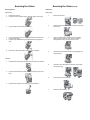
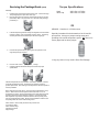
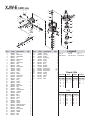
Service Manual
19
Model:
XJW-E
59
20
51
19
50
26
20
23
25
24
11
13
15
16
17
14
49
57
18
34
27 28
29
30
53
31
22
12
58
35
21
45
32
33
46
36
59
5
4
8
9
55
56
44
43
42
47
54
41
10
7
2
6
5
1
3
40
39
38
37
52
Servicing the Valves
Servicing the Valves (cont)
Discharge Valves:
Inlet Valves:
Disassembly:
Disassembly:
1.
2.
Remove the valve cap
Inspect the valve cap O-Ring for any damage, replace if necessary.
3.
Using a needle nose pliers remove the valve.
4.
Use a small probe to move the poppet up and down to assure that it
is functioning properly.
Inspect for any debris that may be lodged between the poppet and
seat.
5.
6.
1.
Remove the manifold.
2.
Remove low pressure seals, insert screwdriver under seal
lip and lift up.
3.
Using a reversible pliers, carefully remove the packing
retainers (plunger guides). Note: You do not want to
damage these so they can be reused if not worn.
4.
Remove the high-pressure packing by pulling straight out
with your finger.
5.
Pull out the valve cage/head ring assembly, valve poppet,
spring and O-Ring.
6.
Inspect for any debris or damage.
7,
Remove the valve O-Ring.
Remove the valve seat O-Ring and inspect for any damage.
Assembly:
1.
2.
3.
Install the valve seat O-Ring squarely into the bottom of the manifold.
Insert the valve assembly squarely into the port pushing it into the ORing.
Install the valve cap and torque to the proper specifications.
Servicing the Valves (cont)
Assembly:
1.
Install the valve seat O-Ring squarely into the bottom of the manifold.
Servicing the Packings/Seals
Packings:
Disassembly:
To access the water seals for inspection or replacement, you will first need
to remove the head of the pump.
Note: It is important to make note of the order in which the components of
the packing stack are arranged and facing during disassembly.
2.
Insert the valve assembly and push squarely into the O-Ring.
1.
2.
3.
3.
4.
5.
6.
Install the high-pressure packing by placing it into the cylinder at an
angle and then pushing into place. Note: The point of the “V” or flat
side of the packing is pointed at you.
Lubricate the packing retainer O-Ring with a light film of oil and
install it into the cylinder.
Push it completely into place. Note: The O-Ring will seat just inside
the manifold and you will hear a slight pop.
Insert the low pressure seal by placing it into the cylinder in at an
angle and pushing it into place.
Note: The packing stacks will not always stay in the head of the pump
when it is removed. Sometimes one or more components of the packing
stack will come out of the head and stay on the plunger.
4.
To remove any components that stay on the plungers simply twist
back and forth while pulling up.
5.
Remove low pressure seals inert screwdriver under seal lip and lift
up.
6.
Remove the piston guides from the head by using a reverse plier
(preferably rubber coated) inserted into the center of the piston
guide.
Use a back and forth twisting motion while pulling up (clockwise and
counterclockwise).
Another method is to use a two-prong slide hammer puller. Insert the
prongs into the piston guide allowing the prongs to grab under the
support ring then use the slide hammer to pull the packing stack up
and out of the head.
7.
8.
7.
8.
Remove the head bolts.
Insert small pry bars between the head and body at opposite corners
and apply pressure down on one pry bar and up on the other pry bar.
Lift the head up and away from the body.
Put a thin coat of oil on the plungers and packings.
Carefully install the manifold and torque the bolt to the proper
specifications.
Note: Damage to the piston guides and or the seals may occur during
removal. Inspect carefully before reusing any components of the packing
stack.
9.
Valve life is dependant on many variables. Hard water, cavitation, corrosion,
chemicals and equipment care. The valves are a wear item and need
periodic replacement. Worn O-Rings or damaged valves will cause
pressure loss and pulsations.
Remove the high-pressure packing by pulling straight out with your
finger.
Servicing the Packings/Seals (cont)
Assembly:
1.
2.
Install the high-pressure seal into the head. Note: It should fit snugly.
The packing support is part of the valve cage.
Place the high-pressure seal at an angle and work it into the cylinder.
(All models). Note: The point of the “V” or flat side of the packing is
pointed at you.
Torque Specifications
Head
Valve Cap
443 in/lbs or 37 ft/lbs
443 in/lbs or 37 ft/lbs
Oil
AR64545 - Container is 4.5 fluid ounces
4.
Lubricate the packing retainer O-Ring with a light film of oil and install
it into the cylinder. Push it completely into place. Note: The O-Ring
will seat just inside the manifold and you will hear a slight pop.
5.
Insert the low-pressure seal by placing it into the cylinder in at an
angle and pushing it into place.
Specially formulated for the demands of the XJ and SJ
pump series. Keep your pumps running strong and
operating with normal temperature specs. No other oil is
factory approved for these pumps.*
*Using any other oil may result in Drive End Damage.
6.
7.
Put a thin coat of oil on the plungers and packings.
Carefully install the manifold and torque the bolt to the proper
specifications.
Valve life is dependant on many variables. Hard water, cavitation, corrosion,
chemicals and equipment care. The valves are a wear item and need
periodic replacement. Worn O-Rings or damaged valves will cause pressure
loss and pulsations.
Note: Water seals are wear items. Life of the seals is dependent on many
factors. Water seals should be replaced when water leak or a loss of
performance is noticed. Prompt replacement of worn seals will insure peak
operating performance and trouble free operation. The water seals and
their respective components sometimes referred to as the packing stack,
will vary slightly between models. But the constant between models is that
the packing stack will consist of the following items.
Piston Guides – which usually house the low-pressure seal
Low-Pressure Seals
Piston Guide O-Rings
High-Pressure Seals
Support Rings
XJW-E 3400 RPM
19
59
20
51
19
50
26
20
23
25
24
49
57
18
17
16
58
34
15
35
13
30
11
53
29
14
27 28
45
31
32
22
33
12
21
46
36
59
5
4
8
47
43
9
55
56
44
54
42
41
10
40
7
2
52
39
6
38
5
1
Pos.
1
2
3
4
5
6
7
8
9
10
11
12
13
14
15
16
17
18
19
20
21
22
23
24
25
26
27
28
29
30
31
32
33
34
35
36
37
38
39
40
41
42
43
Code
1980300
392840
1980540
1080070
1980220
1980520
1080041
1080401
1080250
1980530
880830
740290
800560
1271170
1080190
1271160
1980200
1470210
880581
820510
1980310
650530
1981500
1260162
960160
1989061
1560490
480480
1250280
1560520
1460430
1540170
1080091
394280
1200690
1270141
1989060
2460180
1981470
770130
1260440
1980170
1980410
3
Description
Nut
Grub screw
Handleinsert
Pin
Plate spring
Spring
Upper piston
Ring
O-Ring
Piston guide
O-Ring
O-Ring
O-Ring
Ring
O-Ring
Lower piston
Valve seat
O-Ring
Plug
O-Ring
Screw
Washer
Pump head
Plug
O-Ring
Complete valve
Hose tail
O-Ring
Ball
Spring
O-Ring
Jet
Spring
O-Ring
O-Ring
Detergent injector
Complete valve
Gasket
Piston guide
O-Ring
Gasket
Ring
Seal
37
Qty.
Pos.
1
1
1
1
2
1
1
1
1
1
1
1
1
1
2
1
1
1
2
2
3
3
1
3
3
6
1
1
1
1
1
1
1
1
1
1
3
3
3
3
3
3
3
44
45
46
47
48
49
50
51
52
53
54
55
56
57
58
59
Code
770090
1980460
740290
1980740
180030
1981140
1981440
1980150
1981670
161060
1981630
1981640
1981880
1980430
1980340
1981430
1981730
1981130
Description
O-Ring
Housing
O-Ring
Brass plug
Screw
Spring
Piston
Ring
Bearing
Bearing
Hollow shaft
Hollow shaft
Hollow shaft
Spacer
O-Ring
Flange
Seal
Plate
Legend
Qty.
1
1
1
1
4
3
3
3
1
1
!1
"1
#1
3
1
1
1
1
For !
For "
For #
XJW-E2G22
XJW-E2.5G22
XJW-E3G22
Repair Kits
Water Seals
Valves
Pistons
Oil Seals
Kit 2582
Kit 2581
Kit 2593
Kit 2511
Pos. Qty. Pos. Qty.
38
40
41
42
55
3
3
3
3
3
26
37
3
3
Pos. Qty. Pos. Qty.
50
3
O-Rings
Kit 2583
Pos. Qty. Pos. Qty.
8
9
11
12
13
14
1
1
1
1
1
1
15
18
20
25
28
29
2
1
2
3
1
1
Pos. Qty.
30
31
34
35
46
58
1
1
1
1
1
1
43
44
56
3
1
1