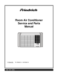
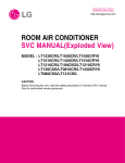
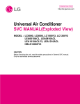
1
ORDER NO. RAC0209003C1
E9
Service Manual
Room Air Conditioner
CW-XC103HU
CW-XC118HU
CW-XC123HU
CW-XC143HU
WARNING
This service information is designed for experienced repair technicians only and is not designed for use by the general public.
It does not contain warnings or cautions to advise non-technical individuals of potential dangers in attempting to service a product.
Products powered by electricity should be serviced or repaired only by experienced professional technicians. Any attempt to
service or repair the product or products deal with in this service information by anyone else could result in serious injury or death.
R
© 2002 Matsushita Electric Industrial co., Ltd.
All rights reserved. Unauthorized copying and
distribution is violation of law.
CONTENTS
1. PREFACE
3. INSTALLATION
1.1 SAFETY PRECAUTIONS................................2
1.2 SPECIFICATIONS...........................................3
1.3 FEATURES......................................................4
2. DISASSEMBLY INSTRUCTIONS
2.1 MECHANICAL PARTS ....................................6
2.1.1 FRONT GRILLE .....................................6
2.1.2 CABINET ................................................6
2.1.3 CONTROL BOX .....................................6
2.2 AIR HANDLING PARTS ..................................7
2.2.1 AIR GUIDE AND BLOWER ....................7
2.2.2 FAN ........................................................7
2.2.3 SHROUD ................................................8
2.3 ELECTRICAL PARTS......................................8
2.3.1 OVERLOAD PROTECTOR ....................8
2.3.2 COMPRESSOR......................................8
2.3.3 CAPACITOR...........................................9
2.3.4 POWER CORD ......................................9
2.3.5 THERMOSTAT .......................................9
2.3.6 SYNCHRONOUS MOTOR .....................9
2.3.7 MOTOR ................................................10
2.4 REFRIGERATION CYCLE ............................10
2.4.1 CONDENSER.......................................10
2.4.2 EVAPORATOR.....................................10
2.4.3 CAPILLARY TUBE ...............................11
3.1 SELECT THE BEST LOCATION...................13
3.2 CHECK OF INSTALLATION..........................13
3.3 HOW TO DRAIN............................................13
3.4 HOW TO INSTALL ........................................14
3.4.1 WHEN USING GASKET.......................14
3.4.2 WHEN USING INSTALLATION KITS...14
4. TROUBLESHOOTING GUIDE
4.1 OUTSIDE DIMENSIONS ...............................17
4.2 PIPING SYSTEM...........................................18
4.3 TROUBLESHOOTING GUIDE ......................19
5. SCHEMATIC DIAGRAM
5.1 CIRCUIT DIAGRAM ......................................27
5.2 ELECTRONIC CONTROL DEVICE...............28
5.3 COMPONENTS LOCATION(FOR MAIN P.C.B ASM) ...29
5.4 COMPONENTS LOCATION(FOR DISPLAY P.C.B ASM)...30
6. EXPLODED VIEW ..................................31
7. REPLACEMENT PARTS LIST ........33
1. PREFACE
This SERVICE MANUAL provides various service information, including the mechanical and electrical
parts etc. This room air conditioner was manufactured and assembled under a strict quality control system.
The refrigerant is charged at the factory. Be sure to read the safety precautions prior to servicing the unit.
1.1 SAFETY PRECAUTIONS
1. When servicing the unit, set the POWER SWITCH to OFF and unplug the power cord.
2. Observe the original lead dress.
If a short circuit is found, replace all parts which have been overheated or damaged by the short circuit.
—2—
1.2 SPECIFICATIONS
MODELS
ITEMS
POWER SUPPLY
CW-XC103HU
CW-XC118HU
CW-XC123HU
CW-XC143HU
1, 115, 60
Ø, V, Hz
Btu/h.
9,800
11,800
12,000
13,800
POWER INPUT
W
910
1,090
1,110
1,280
RUNNING CURRENT
A
8.4
10.0
10.2
11.8
Btu/h.W
10.8
10.8
10.8
10.8
COOLING CAPACITY
EER
OPERATING
INDOOR
°F(°C)
DB : 80(26.7) WB : 67(19.4)
CONDITION
OUTDOOR
°F(°C)
DB : 95(35) WB : 75(23.9)
REFREIGERANT (R-22) CHARGE
490g(17.3 oz)
500g(17.6 oz)
500g(17.6 oz)
530g(18.7 oz)
EVAPORATOR
2 ROW 16 STACKS,SLIT-FIN TYPE
2 ROW 13 STACKS,SLIT-FIN TYPE
CONDENSER
2 ROW 18 STACKS,LOUVERED-FIN TYPE
2 ROW 17 STACKS,LOUVERED-FIN TYPE
FAN
FAN SPEED
INDOOR
TURBO FAN
OUTDOOR
PROPELLER TYPE FAN WITH SLINGER-RING
FAN/COOLING
3/3
6 POLES
FAN MOTOR
OPERATION CONTROL
REMOTE CONTROLLER
ROOM TEMP. CONTROL
THERMISTOR
AIR DIRECTION
CONTROL
MANUAL
VERTICAL
HORIZONTAL
AUTO
MANUAL
SLIDE IN-OUT CHASSIS
CONSTRUCTION
PROTECTOR
AUTO
COMPRESSOR
OVERLOAD PROTECTOR
FAN MOTOR
INTERNAL THERMAL PROTECTOR
3 WIRE WITH GROUNDING
POWER CORD
ATTACHMENT PLUG (CORD-CONNECTED TYPE)
DRAIN PIPE OR SPLASHED BY FAN SLINGER
DRAIN SYSTEM
NET WEIGHT
DIMENSION(W*H*D)
lbs(kg)
inch(mm)
95(43)
100(45)
23 5/8*14 31/32*22 5/16 (600*380*567)
* DB:Dry Bulb
** WB:Wet Bulb
❈ The specifications will be changed without notice for further improvement.
—3—
115(52)
1.3 FEATURES
■ VENTILATION
The ventilation lever must be in the CLOSE position in order to maintain the best cooling conditions.
When fresh air is necessary in the room, set the ventilation lever to the OPEN position.
The damper is opened and room air is drawn out.
Part B
Part A
CLOSE
VENT
OPEN
NOTE: Before using the ventilation feature, and prior to installing the front grille, pull down part
until level with part
.
■ CW-XC118HU
REMOTE CONTROL
DISPLAY
2
5
OPERATION
4
5
TIMER
MODE
2
1
3
1
TEMP
6
FAN SPEED
3
4
Precaution: The Remote Control unit will not function properly if strong light strikes the sensor window of the air
conditioner or if there are obstacles between the Remote Control unit and the air conditioner.
ON/OFF TIMER BUTTON
You can set the time when the unit will turn on or turn off
automatically by pressing the timer button. If the unit is
operating, this button controls the time it will be turned
off. If the unit is off state, this button controls the time it
will start. Every time you push this button, the remaining
time will be set as follows.
- Stopping operation
• (1Hour → 2Hours → 3Hours → 4Hours → 5Hours →
6Hours → 7Hours → 8Hours → 9Hours → 10Hours →
11Hours → 12Hours → 0Hour → 1Hour → 2Hours →... )
• The Setting Temperature will be raised by 2°F(1°C)
30min. later and by 2°F(1°C) after another 30 min.
- Starting operation
• (1Hour → 2Hours → 3Hours → 4Hours → 5Hours →
6Hours → 7Hours → 8Hours → 9Hours → 10Hours →
11Hours → 12Hours → 0Hour → 1Hour → 2Hours → ... )
OPERATION BUTTON
To turn the air conditioner ON, push the button. To turn
the air conditioner OFF, push the button again.
This button takes priority over any other buttons. When
you first turn it on, the air conditioner is on the High cool
mode and the temp. at 72°F (22°C).
OPERATION MODE SELECTION BUTTON
Every time you push this button, it will toggle between
COOL and FAN.
FAN SPEED SELECTION BUTTON
Every time you push this button, it is set as follows.
[High(F3) → Low(F1) → Med(F2) → High(F3) →...]
ROOM TEMPERATURE SETTING BUTTON
This button can automatically control the temperature of
the room. The temperature can be set within a range of
60°F to 86°F by 1°F (16°C to 30°C by 1°C).
Select the lower number for lower temperature of the
room.
6 REMOTE CONTROL SIGNAL RECEIVER
—4—
■ CW-XC103HU, CW-XC123HU, CW-XC143HU
DISPLAY
REMOTE CONTROL
5
OPERATION
1
TEMP
3
2
8
TIMER
5
MODE
2
AIR
SWING
6
FAN SPEED
4
ECONOMY
4
1
3
7
6
Precaution: The Remote Control unit will not function properly if strong light strikes the sensor window of the air
conditioner or if there are obstacles between the Remote Control unit and the air conditioner.
OPERATION BUTTON
To turn the air conditioner ON, push the button. To turn the air conditioner OFF, push the button again.
This button takes priority over any other buttons. When you first turn it on, the air conditioner is on the High cool mode and
the temp. at 72°F (22°C).
OPERATION MODE SELECTION BUTTON
Every time you push this button, it will toggle between COOL, FAN.
ROOM TEMPERATURE SETTING BUTTON
This button can automatically control the temperature of the room. The temperature can be set within a range of 60°F to
86°F by 1°F (16°C to 30°C by 1°C).
Select the lower number for lower temperature of the room.
FAN SPEED SELECTION BUTTON
Every time you push this button, it is set as follows.
[High(F3) → Low(F1) → Med(F2) → High(F3) →...]
ON/OFF TIMER BUTTON
You can set the time when the unit will turn on or turn off automatically by pressing the timer button. If the unit is operating,
this button controls the time it will be turned off. If the unit is off state, this button controls the time it will start. Every time
you push this button, the remaining time will be set as follows.
- Stopping operation
(1Hour → 2Hours → 3Hours → 4Hours → 5Hours → 6Hours → 7Hours → 8Hours → 9Hours → 10Hours → 11Hours →
12Hours → 0Hour → 1Hour → 2Hours →... )
The Setting Temperature will be raised by 2°F(1˚C) 30min. later and by 2°F(1˚C) after another 30 min.
- Starting operation
(1Hour → 2Hours → 3Hours → 4Hours → 5Hours → 6Hours → 7Hours → 8Hours → 9Hours → 10Hours → 11Hours →
12Hours → 0Hour → 1Hour → 2Hours → ... )
6 AIR SWING BUTTON
This button can automatically control the air flow direction.
7 ECONOMY BUTTON
If you push this button, the fan stops when the compressor stops cooling. Approximately every 3 minutes the fan will turn
on and check the room air temperature to determine if cooling is necessary.
8 REMOTE CONTROL SIGNAL RECEIVER
—5—
2. DISASSEMBLY INSTRUCTIONS
— Before the following disassembly, POWER SWITCH set to OFF and disconnect the power cord.
2.1 MECHANICAL PARTS
2.1.1 FRONT GRILLE
1. Open the lnlet grille upward .
2. Remove the screw which fastens the front grille.
3. Pull the front grille from the right side.
4. Remove the front grille.
5. Re-install the component by referring to the
removal procedure, above.(See Figure 1)
Figure 1
2.1.2 CABINET
1. After disassembling the FRONT GRILLE, remove
the 2 screws which fasten the cabinet at both
sides.
2. Remove the 2 screws which fasten the cabinet at
back.
3. Pull the base pan forward. (See Figure 2)
4. Remove the cabinet.
5. Re-install the component by referring to the
removal procedure, above.
Figure 2
2.1.3 CONTROL BOX
1. Remove the front grille. (Refer to section 2.1.1)
2. Remove the cabinet. (Refer to section 2.1.2)
3. Remove the 2 screws which fasten the control box
cover.
4. Remove two housings which connect compressor
wire and motor wire in the control box.
5.Discharge the capacitor by placing a 20,000
ohmresistor across the capacitor terminals.
6. Remove the 2 screws which fasten the control
box.
7. Pull the control box forward completely.
8. Re-install the components by referring to the
removal procedure, above. (See Figure 3)
(Refer to the circuit diagram found on pages
34~37 in this manual and on the control box.)
Figure 3
—6—
2.2 AIR HANDLING PARTS
2.2.1 AIR GUIDE AND BLOWER
1. Remove the front grille. (Refer to section 2.1.1)
2. Remove the cabinet. (Refer to section 2.1.2)
3. Remove the control box. (Refer to section 2.1.3)
4. Remove the 4 screws which fasten the brace.
5. Remove the brace.
6. Remove the 2 screws which fasten the evaporator.
7. Move the evaporator forward and pulling it upward
slightly. (See Figure 4)
8. Move the evaporator to the left carefully.
9. Pull out the hook of orifice by pushing the tabs and
remove it. (See Figure 5)
10. Remove the clamp with a hand plier which
secures the blower.
11. Remove the blower.
12. Remove the 4 screws which fasten the air guide
from the barrier.
13. Move the air guide backward, pulling out from the
base pan.
14. Re-install the components by referring to the
removal procedure, above.
Figure 4
Figure 5
2.2.2 FAN
1. Remove the cabinet. (Refer to section 2.1.2)
2. Remove the brace (Refer to section 2.2.1)
3. Remove the 4 screws which fasten the condenser.
4. Move the condenser to the left carefully.
5. Remove the clamp which secures the fan.
6. Remove the fan. (See Figure 7)
7. Re-install by referring to the removal procedure.
Figure 6
Figure 7
—7—
2.2.3 SHROUD
1. Remove the fan. (Refer to section 2.2.2)
2. Remove the screw which fastens the shroud.
3. Remove the shroud. (See Figure 8)
4. Re-install the component by referring to the
removal procedure, above.
Figure 8
2.3 ELECTRICAL PARTS
2.3.1 OVERLOAD PROTECTOR
1. Remove the cabinet. (Refer to section 2.1.2)
2. Remove the nut which fastens the terminal cover.
3. Remove the terminal cover. (See Figure 9)
4. Remove all the leads from the overload protector.
5. Remove the overload protector.
6. Re-install the component by referring to the
removal procedure, above.
Figure 9
2.3.2 COMPRESSOR
1. Remove the cabinet. (Refer to section 2.1.2)
2. Discharge the refrigerant system using a FreonTM
Recovery System.
If there is no valve to attach the recovery system,
install one (such as a WATCO A-1) before venting
the FreonTM. Leave the valve in place after
servicing the system.
3. Remove the overload protector. (Refer to section
2.3.1)
4. After purging the unit completely, unbraze the
suction and discharge tubes at the compressor
connections.
5. Remove the 3 nuts and the 3 washers which
fasten the compressor.
6. Remove the compressor. (See Figure 10)
7. Re-install the components by referring to the
removal procedure, above.
Figure 10
—8—
2.3.3 CAPACITOR
1. Remove the control box. (Refer to section 2.1.3)
2. Remove the knobs and the screw which fasten
control panel from control box.
3. Remove the screw which located in the front.
4. Open the bottom side of control box.
5. Remove the screw and the clamp which fastens
the capacitor.
6. Disconnect all the leads of capacitor terminals.
7. Re-install the components by referring to the
removal procedure, above. (See Figure 11)
2.3.4 POWER CORD
1. Remove the control box. (Refer to section 2.1.3)
2. Open the control box. (Refer to section 2.3.3)
3. Disconnect the grounding screw from the control
box.
4. Disconnect the 2 receptacles.
5. Remove a screw which fastens the clip cord.
(See Figure 12)
6. Remove the power cord.
7. Re-install the component by referring to the above
removal procedure, above.
(Use only one ground-marked hole
for ground
connection.)
8. If the supply cord of this appliance is damaged, it
must be replaced by the special cord. (The
special cord means the cord which has the same
specification marked on the supply cord attached
at the unit.)
Figure 11
Figure 12
2.3.5 THERMISTOR
1. Remove the control box. (Refer to section 2.1.3)
2. Open the control box. (Refer to section 2.3.3)
3. Disconnet the thermistor terminals from main
P.W.B assembly.
4. Remove the thermistor.
5. Re-install the components by refereing to the
above removal procedure. (See Figure 13)
Figure 13
2.3.6 SYNCHRONOUS MOTOR
1. Remove the control box. (Refer to section 2.1.3)
2. Unfold the control box. (Refer to section 2.3.3)
3. Remove the crankshaft.
4. Disconnect all the leads of the synchronous
motor.
5. Remove the 2 screws which fasten the
synchronous motor. (See Fig. 14)
6. Re-install the components by referring to the
removal procedure, above.
Figure 14
—9—
2.3.7 MOTOR
1. Remove the cabinet. (Refer to section 2.1.2)
2. Remove the evaporator. (Refer to section 2.2.1)
3. Remove the orifice. (Refer to section 2.2.1)
4. Remove the blower. (Refer to section 2.2.1)
5. Remove the fan. (Refer to section 2.2.2)
6. Remove the control box cover and disconnect 5 or
4 wires of motor housing. (Refer to section 2.1.3)
7. Remove the 2 or 4 screws which fasten the motor
from the mount motor. (See Figure 14)
8. Remove the motor.
9. Re-install the components by referring to the
removal procedure, above.(See Figure 14)
2.4 REFRIGERATING CYCLE
CAUTION
Figure 14
Discharge the refrigerant system using a
FreonTM Recovery System.
If there is no valve to attach the recovery
system, install one (such as a WATCO A-1)
before venting the FreonTM. Leave the valve in
place after servicing the system.
2.4.1 CONDENSER
1. Remove the cabinet. (Refer to section 2.1.2)
2. Remove the 4 screws which fasten the
brace.(Refer to section 2.2.1)
3. Remove the 5 screws which fasten the condenser
and shroud.
4. After discharging the refrigerant completely,
unbraze the interconnecting tube at the condenser
connections.
5. Remove the condenser.
6. Re-install the component by referring to notes.
(See Figure 15)
Figure 15
2.4.2 EVAPORATOR
1. Remove the cabinet. (Refer to section 2.1.2)
2. Remove the 2 screws which fasten the evaporator.
3. Move the evaporator sideways carefully.
(Refer to section 2.2.1)
4. After discharging the refrigerant completely,
unbraze the interconnecting tube at the evaporator
connections.
5. Remove the evaporator.
6. Re-install the component by referring to notes.
(See Figure 16)
Figure 16
—10—
3. Remove the capillary tube.
4. Re-install the component by referring to notes.
2.4.3 CAPILLARY TUBE
1. Remove the cabinet. (Refer to section 2.1.2)
2. After discharging the refrigerant completely,
unbraze the interconnecting tube at the capillary
tube.(See caution above)
NOTES
— Replacement of the refrigeration cycle.
1. When replacing the refrigeration cycle, be sure to
Discharge the refrigerant system using a FreonTM
recovery System.
If there is no valve to attach the recovery system,
install one (such as a WATCO A-1) before venting
the FreonTM. Leave the valve in place after
servicing the system.
2. After discharging the unit completely, remove the
desired component, and unbraze the pinch-off
tubes.
3. Solder service valves into the pinch-off tube ports,
leaving the valves open.
4. Solder the pinch-off tubes with Service valves.
5. Evacuate as follows.
1) Connect the vacuum pump, as illustrated figure
18A.
2) Start the vacuum pump, slowly open manifold
valves A and B with two full turns
counterclockwise and leave the valves open.
The vacuum pump is now pulling through valves
A and B up to valve C by means of the manifold
and entire system.
CAUTION
If high vacuum equipment is used, just crack
valves A and B for a few minutes, then open
slowly with the two full turns counterclockwise.
This will keep oil from foaming and being
drawn into the vacuum pump.
3) Operate the vacuum pump for 20 to 30 minutes,
until 600 microns of vaccum is obtained. Close
valves A and B, and observe vacuum gauge for
a few minutes. A rise in pressure would
indicate a possible leak or moisture remaining in
the system. With valves A and B closed, stop
the vacuum pump.
4) Remove the hose from the vacuum pump and
place it on the charging cylinder. See figure
18B.
Open valve C.
Discharge the line at the manifold connection.
5) The system is now ready for final charging.
6. Recharge as follows :
1) Refrigeration cycle systems are charged from
the High-side. If the total charge cannot be put
in the High-side, the balance will be put in the
suction line through the access valve which you
installed as the system was opened.
2) Connect the charging cylinder as shown in figure
18B.
With valve C open, discharge the hose at the
manifold connection.
3) Open valve A and allow the proper charge to
enter the system. Valve B is still closed.
4) If more charge is required, the high-side will not
take it. Close valve A.
5) With the unit running, open valve B and add the
balance of the charge.
a. Do not add the liquid refrigerant to the Lowside.
b. Watch the Low-side gauge; allow pressure to
rise to 0.2 Mpa.
c. Turn off valve B and allow pressure to drop.
d. Repeat steps b. and c. until the balance of the
charge is in the system.
6) When satisfied the unit is operating correctly,
use the pinch-off tool with the unit still running
and clamp on to the pinch-off tube. Using a tube
cutter, cut the pinch-off tube about 2 inches from
the pinch-off tool. Use sil-fos solder and solder
pinch-off tube closed. Turn off the unit, allow it to
set for a while, and then test the leakage of the
pinch-off connection.
—11—
Equipment needed: Vacuum pump, Charging cylinder, Manifold gauge, Brazing equipment. Pin-off tool capable
of making a vapor-proof seal, Leak detector, Tubing cutter, Hand Tools to remove components, Service valve.
COMPOUND GAUGE
CONDENSER
(HIGH PRESSURE SIDE)
MANIFOLD
GAUGE
A
B
CAPILLARY TUBE
SEE INSETS
BELOW
EVAPORATOR
(LOW PRESSURE SIDE)
COMPRESSOR
LOW
HI
A
B
B
A
EXTERNAL
VACUUM PUMP
CHARGING
CYLINDER
C
Figure 17B-Charging
Figure 17A-Pulling Vacuum
—12—
3. INSTALLATION
3.1 SELECT THE BEST LOCATION
AWNING
COOLED AIR
FENCE
HEAT
RADIATION
76.2cm(30")
~152.4cm(60")
1.To prevent vibration and noise, make sure the unit
is installed securely and firmly.
2.Install the unit where the sunlight does not shine
directly on the unit.
3.The outside of the cabinet must extend outward for
at least 30.48cm(12") and there should be no
obstacles, such as a fence or wall, within
50.8cm(20") from the back of the cabinet because it
will prevent heat radiation of the condenser.
Restriction of outside air will greatly reduce the
cooling efficiency of the air conditioner.
ABOUT 12.7mm(1/2")
Over 50.8cm(20")
CAUTION
Figure 18
All side louvers of the cabinet must remain
exposed to the outside of the structure.
4.Install the unit a little slanted so the back is slightly
lower than the front (about 12.7mm(1/2 ")). This will
help force con-densed water to the outside.
5.Install the unit from the bottom about
76.2cm(30")~152.4cm(60") above the floor level.
3.2 CHECK OF INSTALLATION
The setting conditions must be checked prior to
initial starting.
The undermentioned items are especially important
checking points when the installation is finished.
1. Grounding wire (Green or Green and Yellow) is
provided in the power cord. The green wire must
be grounded.
2. Connect to a single-outlet 15A circuit.
(or 20A circuit for Electric Heater Model)
3. To avoid vibration or noise, make sure the air
conditioner is installed securely.
4 Avoid placing furniture or draperies in front of the
air inlet and outlet.
BASE PAN
BOTTOM
1
HOLE RUBBER
Figure 19
3.3. HOW TO DRAIN
(When using drain pipe)
The air conditioner must be installed horizontally or
tilted slightly to the outside for proper water
drainage.
On exceptionally hot and humid days the air
conditioner may overflow conclensed water.
If the air conditioner is used in hot and a high
humidity zone, exchange the
HOLE RUBBER
for the
DRAIN PIPE.(See figure 19, figure 20.)
—13—
BASE PAN
BOTTOM
2
Figure 20
DRAIN PIPE
3.4 HOW TO INSTALL
3.4.1 WHEN USING GASKET
A
2
A
1
2
RIGHT SIDE
B
B
H
3
D
4
HORIZONTAL
LINE
E
1
F
1. WINDOW (WIDTH-A, HEIGHT-B)
2. GASKET
3. WALL
4. DETAILS 5.1 x 30 ROUND HEAD WOOD
SCREWS
A
B
C
D
E
F
625mm
(245/8")
392mm
(157/16")
280mm
(111/32")
30mm
(11/16")
0~25mm
(0~1")
OVER 420mm
(OVER 1617/32")
H
I
5~10mm
-5~5mm
(3/16"~3/8") (-3/16"~3/16")
3.4.2 WHEN USING INSTALLATION KITS
A. WINDOW REQUIREMENTS
60.58cm(27") to
99.09cm(39")
40.64cm(16") min
Stool
This unit is designed for installation in
standard double hung windows with actual opening
widths from 68.58cm(27") to 99.09cm(39").
The top and bottom window sash must open
sufficiently to allow a clear vertical opening of 16"
from the bottom of the upper sash to the window
stool.
Interior wall
Offset
12.7mm(1/2") to
6.35mm(1/4")
Sill
Exterior
74.6cm(235/8" min)
(Without frame curtain)
B. INSTALLATION KITS CONTENTS
2
1
5
11
6
3
4
7
8
NO.
1
2
3
4
5
6
7
8
9
10
11
12
13
12
9
10
13
—14—
NAME OF PARTS
FRAME CURTAIN
SILL SUPPORT
BOLT
NUT
SCREW(TYPE A) (10mm(2/5"))
D5.1mm(0.2")
SCREW(TYPE B)
16mm(0.63")
D4.1mm(0.17")
SCREW(TYPE C)
16mm(0.63")
FOAM-STRIP
FOAM-PE (600mm x 25mm x 2mm)
FRAME GUIDE
WINDOW LOCKING BRACKET
FOAM-PE (920mm x 30mm x 2mm)
DRAIN PIPE
Q'TY
2
2
2
2
16
3
5
1
1
2
1
1
1
SUGGESTED TOOL REQUIREMENTS
SCREWDRIVER(+, -), RULER, KNIFE, HAMMER, PENCIL, LEVEL
Shipping screws
PREPARATION OF CHASSIS
1. Remove the screws which fasten the cabinet at
both sides and at the back.
2. Slide the unit out from the cabinet by gripping the
base pan handle and pulling forward while
bracing the cabinet.
3. Remove EPS Material.
4. Cut the window sash seal to the proper length. Peel
off the backing and attach the foam-pe
to the
underside of the window sash.
5. Remove the backing from the top upper guide
and attach it to the bottom of the upper
Foam PE
guide.
6. Attach the upper guide onto the top of the cabinet
with 3 type A screws.
7. Insert the frame guides
into the bottom of the
cabinet.
8. Insert the Frame Curtain
into the upper guide
and frame guides .
9. Fasten the curtains to the unit with 4 Type A screws
at the both sides.
EPS Material
9
12
CABINET INSTALLATION
1. Open the window. Mark a line on center of the
window stool(or desired air conditioner location).
Carefully place the cabinet on the window stool and
align the center mark on the bottom front with the
center line marked in the window stool.
5
(Type A)
5
10
5
2. Pull the bottom window sash down behind the
upper guide until it meets.
(Type A)
10
NOTE:
• Do not pull the window sash down so tightly that the
movement of Frame Curtain is restricted.
Upper Guide
Front Angle
Window Sash
Window stool
Figure 21
Upper guide
Cabinet
Frame Curtain 1
Figure 22
—15—
3. Loosely assemble the sill support using the parts
in Figure 23.
INDOOR
Bolt 3
OUTDOOR
Sill Support 2
Figure 23
Nut 4
4. Select the position that will place the sill
support near the outer most point on sill
(See Figure 23)
10 Frame Guide
5 Screw(Type A)
About 1/2"
NOTE: Be careful when you install the cabinet (frame
are broken easily).
guides
5. Attach the sill support to the cabinet track hole in
relation to the selected position using
2 Type A screws in each support (See Figure 24).
INDOOR
Cabinet
OUTDOOR
Figure 24
6. The cabinet should be installed with a very slight
tilt(about 12.7mm 1/2") downward toward the
outside (See Figure 25).
Adjust the bolt and the nut of sill support for
balancing the cabinet.
Screw(Type A) 5
About 1/2"
Screw(Type B) 6
Sill support 2
7. Attach the cabinet to the window stool by
driving the screws (Type B: Length sixteen
millimeters and below.) through the front angle into
window stool 16mm (5/8").
Sash track
8. Pull each Frame curtain properly to each window
sash track, and repeat step 2.
Front Angle
Sill support 2
Screw(Type B) 6
Figure 25
9. Attach each Frame curtain to the window sash by
using screws (Type C).
(See Figure 26)
Type C
7
Figure 26
—16—
10. Slide the unit into the cabinet.(See Fig. 27)
CAUTION: For security purpose, reinstall screws(Type
A) at the cabinet's sides.
Power cord
Screw(Type A)
Screw(Type A)
11. Cut the foam-strip
to the proper length and insert
between the upper and lower window sash.
(See Fig. 28)
Figure 27
Foam-Strip 8
Figure 28
12. Attach the window locking bracket
screw. (See Fig. 29)
with a type C
11
Figure 29
13. Attach the front grille to the cabinet by inserting the
tabs on the grille into the tabs on the front of the
cabinet. Push the grille in until it snaps into
place.(See Fig. 30)
14. Lift the inlet grille and secure it with a type A screw
through the front grille.(See Fig. 31)
Figure 30
Figure 31
Figure 32
4. TROUBLESHOOTING GUIDE
4.1 OUTSIDE DIMENSIONS
unit: mm(inch)
31
380(14 /32")
—17—
4.2 PIPING SYSTEM
CONDENSER COIL
FAN
CAPILLARY TUBE
MOTOR
COMPRESSOR
BLOWER
EVAPORATOR COIL
Figure 33 is a brief description of the important components and their function in what is called the refrigeration
system. This will help you to understand the refrigeration cycle and the flow of the refrigerant in the cooling cycle.
ROOM AIR CONITIONER
CYCLE OF REFRIGERATION
EVAPORATOR COILS
CONDENSER COILS
COMPLETE LIQUID
BOIL OFF POINT
COOLED
AIR
SUCTION LINE
COOL LOW PRESSURE VAPOR
VAPOR INLET
HOT
DISCHARGED
AIR
ROOM AIR HEAT LOAD
MOTOR
OUTSIDE COOLING
AIR FOR REFRIGERANT
PASS THROUGH
COMPRESSOR
OIL
LIQUID
PRESSURE
DROP
LIQUID OUTLET
(LIQUID REFRIGERANT)
HIGH PRESSURE VAPOR
LIQUID REFRIGERANT
CAPILLARY TUBE
Figure 33
—18—
LOW PRESSURE VAPOR
4.3 TROUBLESHOOTING GUIDE
In general, possible trouble is classified in two kinds.
The one is called Starting Failure which is caused from an electrical defect, and the other is ineffective Air
Conditioning caused by a defect in the refrigeration circuit and improper application.
Unit runs but poor cooling.
Ineffective Cooling
Check cold air circulation
for smooth flow.
Dirty indoor coil
(Heat exchanger)
Check outdoor coil
(heat exchanger) & the fan
operation.
Check heat load
increase.
Clean condenser.
Check gas leakage.
Not on separate circuit.
Malfunction of fan
Clogged of air filter.
Repair gas leak.
Replacement of unit if the
unit is beyond repair.
Obstruction at air outlet
Check inside gas
pressure.
Adjusting of refrigerant
charged.
Stop of auto air-swing
Malfunction of compressor.
Correct above trouble
Check clogging in refrigeration circuit.
Repair clogging in refrigeration circuit.
Replacement of
compressor.
Satisfactory operation with
temperature difference of
inlet & outlet air ;
44~50°F(7~10°C)
—19—
Fails to Start
Check of power source.
Check circuit breaker
and fuse.
Check of control switch
setting.
Gas leakage of feeler bulb
of thermostat
Check of control switch.
Compressor only fails to
start.
Fan only fails to start.
Improper wiring.
Drop of power voltage.
Improper thermostat setting.
Defect of fan motor
capacitor.
Defect of compressor
capacitor.
Loose terminal connection.
Capacitor check.
Irregular motor resistance
( ).
Irregular motor insulation
( ).
Improper wiring.
Replacement
Replacement of fan motor.
Irregular motor resistance (
)
Irregular motor insulation (
)
Regular but fails to start.
Replacement of compressor
(locking of rotor, metal).
Replacement of compressor
(Motor damaged)
—20—
■ ELECTRICAL PARTS TROUBLESHOOTING GUIDE: CW-XC103HU, CW-XC118HU, CW-XC123HU, CW-XC143HU
Possible Trouble 1
The unit does not operate.
Is the Trans input power
AC 115V?
NO
•• Check
Check the
the Fuse.
Fuse.
•• Check
the
Check thewiring
wiringdiagram.
diagram.
YES
Is the Trans output power
about AC 13V?
NO
Is shorted the Trans. output?
YES
Is output Voltage of IC01D
DC 12V?
YES
NO
• Check the Main
PCB pattern.
• Exchange the Trans.
• Exchange D02D~D05D.
• Exchange IC01D.
NO
YES
Is output Voltage of IC02D
DC 5V?
NO
• Exchange IC02D.
YES
Is the reset circuit all right?
(The No.18 of
Micom is 5V.)
NO
• Exchange IC01A, C02A.
YES
Is the
connection between
Main and Display
all right?
NO
• Connect connector
exactly.
NO
• Check the PCB
pattern.
YES
Is the voltage No.18 of Micom
DC 5V?
YES
Exchange Main PCB Ass'y.
—21—
Possible Trouble 2
The compressor does not operate.
Is setting
Temp. lower than Room
Temp.-0.5°C?
NO
• Select the setting Temp. to lower Number.
YES
Is the voltage No.10
of IC01M 0V?
NO
Is the voltage N0.7 of
IC01M DC 5V?
YES
YES
• Check the RY-COMP.
• Check the wiring
Diagram.
• Exchange IC01M.
NO
Is the Unit for 3 minutes
delay?
NO
YES
• Wait 3 Minutes.
• Exchange MAIN
PCB Ass'y.
Possible Trouble 3
Is the wire connection of
RY-COMP all right?
The compressor always operate.
• Connect LEAD Wire to
RY-COMP again.
NO
YES
• Check the RY-COMP.
—22—
Possible Trouble 4
FAN does not operate.
Is the voltage NO.1 or 2 or 4
of IC01M DC 5V?
NO
• Exchange IC01M.
YES
Is the voltage NO.13 or 15 or 16
of IC01M 0V?
NO
• Exchange IC01M.
YES
• Check the RY-Hi or
RY-Med or RY-Low.
• Check the wiring diagram.
—23—
Possible Trouble 5
Remote controller does not operate.
Is the voltage of Battery
about over 2.3V?
NO
• Exchange the battery.
YES
Is the voltage No.17
of CN-DISP on Main PCB
Ass'y DC 5V?
NO
••Check
Checkthe
thePCB
PCBpattern.
pattern.
YES
• Connect connector to
CN-DISP2 exactly.
NO
Is the connection of
CN-DISP2 all right?
YES
• Exchange Receiver Ass'y.
Possible Trouble 6
It displays abnormally on display PCB Ass’y.
Is the IC01G all right?
NO
• Exchange IC01G.
YES
NO
Is the connection of
CN-DISP all right?
• Connect connector
to CN-DISP exactly.
NO
YES
Does the Q01G,
Q02G, Q03G, Q04G operate normally
on main PCB Ass'y?
NO
• Exchange Q01G, Q02G,
Q03G, Q04G.
YES
• Exchange the display
PCB Ass'y.
—24—
COMPLAINT
Fan motor will not run.
CAUSE
REMEDY
No power
Check voltage at outlet. Correct if none.
Power supply cord
Check voltage to rotary switch. If none, check power
supply cord. Replace cord if circuit is open.
Wire disconnected or
connection loose
Connect wire. Refer to wiring diagram for terminal
identification. Repair or replace loose terminal.
Capacitor (Discharge
capacitor before testing.)
Test capacitor.
Replace if not within ±10% of manufacturer's rating.
Replace if shorted, open, or damaged.
Will not rotate
Fan blade hitting shroud or blower wheel hitting
scroll. Realign assembly.
Units using slinger ring for condenser fan must have
1
/4 to 5/16 inch clearance to the base. If it hits the
base, shim up the bottom of the fan motor with
mounting screw(s).
Check fan motor bearings; if motor shaft will not
rotate, replace the motor.
Fan motor runs
intermittently
Revolves on overload.
Check voltage. If not within limits, call an electrician.
Test capacitor.
Check bearings. Does the fan blade rotate freely?
If not, replace fan motor.
Pay attention to any change from high speed to
low speed. If the speed does not change, replace the
motor.
Fan motor noise.
Compressor will not run,
but fan motor runs.
Fan
If cracked, out of balance, or partially missing,
replace it.
Blower
If cracked, out of balance, or partially missing,
replace it.
Loose clamper
Tighten it.
Worn bearings
If knocking sounds continue when running or loose,
replace the motor. If the motor hums or noise
appears to be internal while running, replace motor.
Voltage
Check voltage.
If not within limits, call an electrician.
Wiring
Check the wire connections, if loose, repair or
replace the terminal. If wires are off, refer to wiring
diagram for identification, and replace. Check wire
locations. If not per wiring diagram, correct.
Rotary
Check for continuity, refer to the wiring diagram for
terminal identification. Replace the switch if circuit is
open.
—25—
COMPLAINT
Compressor will not run,
but fan motor runs.
Compressor cycles on
overload.
Compressor cycles on
overload.
Compressor cycles on
overload.
Insufficient cooling or
heating
Excessive noise
CAUSE
REMEDY
Thermostat
Check the position of knob If not at the coldest
setting, advance the knob to this setting and restart
unit.
Check continuity of the thermostat. Replace
thermostat if circuit is open.
Capacitor (Discharge
capacitor before servicing.)
Check the capacitor.
Replace if not within ±10% of manufacturers rating.
Replace if shorted, open, or damaged.
Compressor
Check the compressor for open circuit or ground. If
open or grounded, replace the compressor.
Overload
Check the compressor overload, if externally
mounted. Replace if open. (If the compressor
temperature is high, remove the overload, cool it,
and retest.)
Voltage
Check the voltage.
If not within limits, call an electrician.
Overload
Check overload, if externally mounted.
Replace if open. (If the compressor temperature is
high, remove the overload, cool, and retest.)
Fan motor
If not running, determine the cause. Replace if
required.
Condenser air flow
restriction
Remove the cabinet. inspect the interior surface of
the condenser; if restricted, clean carefully with a
vacuum cleaner (do not damage fins) or brush.
Clean the interior base before reassembling.
Condenser fins (damaged)
If condenser fins are closed over a large area on the
coil surface, head pressures will increase, causing
the compressor to overload. Straighten the fins or
replace the coil.
Capacitor
Test capacitor.
Wiring
Check the terminals. If loose, repair or replace.
Refrigerating system
Check the system for a restriction.
Air filter
If restricted, clean of replace.
Exhaust damper door
Close if open.
Unit undersized
Determine if the unit is properly sized for the area to
be cooled.
Blower or fan
Check the set screw or clamp. If loose or missing,
correct. If the blower or fan is hitting air guide,
rearrange the air handling parts.
Copper tubing
Remove the cabinet carefully and rearrange tubing
not to contact cabinet, compressor, shroud, and
barrier.
—26—
5. SCHEMATIC DIAGRAM
5.1 CIRCUIT DIAGRAM
■ MODEL : CW-XC103HU, CW-XC123H, UCW-XC143HU, CW-XC118HU
POWER INPUT
WH(BL)
(Ribbed)
(Plain)
GN/YL(GN)
RD
H
PTC
3
COMP.
BK
RD
BL
R
S
C
CN-DISP
BR
5
SYNC
MOTOR
8
10
BR
RY-SYNC
4
ZNR
RY-COMP
4
3
TRANS
FORMER
FUSE 250V/T2A
(115V/T2A)
BL
OLP
9
CN-SYNC
CN-WORK
MAIN P.W.B ASM
OR(BR)
BK
RD
BK
RY-HI
CN-TH1
F
C
DISPLAY P.W.B ASM
6
GN/YL
(GN) CAPACITOR
7
THERMISTOR
RY-MID
MOTOR
BK
BL
RD
OR(BR)
YL
RY-LO
2
BK
BL
RD
OR(BR)
YL
1
BK(BR)
3854AR2330P
WIRING DIAGRAM
❈ SYNC MOTOR : CW-XC103HU, CW-XC123HU, CW-XC143HU only.
LOCATION
NO.
DESCRIPTION
Q'TY PER SET
1
POWER CORD ASSY
1
2
MOTOR ASSY
1
3
COMPRESSOR
1
4
MAIN P.W.B ASSY
1
5
DISPLAY P.W.B ASSY
1
6
THERMISTOR
1
7
CAPACITOR
1
8
CONNECTOR ASSY
1
9
OVERLOAD PROTECTOR
1
10
MOTOR ASSY, SYNC.
1
—27—
5.2 ELECTRONIC CONTROL DEVICE
■ MODEL: CW-XC118HU, CW-XC103HU, CW-XC123HU, CW-XC143HU
FAN
HERM
C
FAN
MOTOR
SYNC
MOTOR
CAPACITOR
MAIN POWER
COMP
2
1
2
2
1
4
3
4
CN-TH1
SMW250-02
12V
RY-SYNC
R22H
5V
12.1K
1%
5V
12.1K
1%
R21H
6.2K
1%
R02H
12.1K
1%
R01H
I
13
12
11
10
1
2
3
4
5
6
7
MED
ION
HVB
SYNC
COMP
23
24
25
26
27
28
29
30
31
32
33
22
34
I
+
21
35
5V
17
16
15
R12F
20K
R02E
20
39
42
14
43
13
44
12
C01A
38
TMP87CH47U
MICOM
18
0.01
50V
19
37
41
1M
20
36
5V
40
R01B
5V
R01E
1K
0.01
50V
C06D
Tx
11
9
10
8
7
6
5
4
3
2
1
C02F
0.001
Rx
SDA
1
4
3
2
+
R01A
20K
1uF
50V
C02A
EEPROM
24LC01BT
3
SDA
SCL
WP
Vcc
A2
A0
GND
A1
Digit4 (Scan4)
SCL
Digit1 (Scan1)
Digit2 (Scan2)
Digit3 (Scan3)
SEG-a
Digit0 (Scan0)
SEG-b
R01F
10K
1K
R01L
ULN2004A
IC01G
C01F
0.001
SEG-c
R02F
10K
C01L
680pF
1
2
3.6V
8
7
6
5
IC01A
5V
20K
R03P
S7136
20K
R02P
150
5V
R01G
150
1K
R04P
16
150
5V
1
R02G
150
R03G
150
15
R04G
150
14
13
R05G
2
4
R06G
150
12
R07G
11
3
12V
6
9
10
5
7
8
CN-DISP
17
17
1
12
5
4
13
1
6
8
9
10
11
14
7
9
8
10
11
3
6
7
15
2
12
16
5V
SW7
Q04G
A101S
TEMP UP
D07F
SW3
ECONOMY
D03F
A/SWING
A/RESTART
AIR PURIFIER
CN-DISP
A101S
Q03G
A101S
Q02G
13
5
A101S
Q01G
4
D08F
b
c
5V
SW6
SW8
Digit0
e
f
AUTO SWING
D06F
ON/OFF
14
SW4
3
MODE
D04F
SW1
a
g
d
C22L
220
10V
d
g
a
6
15
SW5
FAN
D01F
Digit1
a
b
c
d
+
88 SEGMENT
e
10
2
D05F
SW2
5
4
3
2
g
7 f
1 e
8
Vcc
GND
f
16
TEMP DOWN
D02F
TIMER
COOL
DEFROST
DRY/HEAT
FAN
TIMER
ECONOMY
BZ01E
PKM13EPY
-4002
Vout
RECEIVER
b
c
5V
❈ SYNC MOTOR : CW-XC103HU, CW-XC123HU, CW-XC143HU only.
OSC01B
14
IC02D
7805
220
10V
C05D
RT8.00MG
15
12V
0.01
50V
C04D
O
LED out3
Buzzer
Receiver
LOW
16
ULN2004A
IC01M
HI
+
8
IC01D
1000
16V
C03D
9
OR2H
0K
OR1H
R03H
RY-COMP
RY-SYNC
RY-LOW
RY-MED
RY-HI
12V
O
7812
C02D
0.1
50V
Osc in
SEG-g
ROOM-TH
PIPE-TH
CN-SYNC
D05D
1000
35V
D04D
+
C01D
SEG-d
3
D02D
D02D~D05D
1N4004
D03D
TEST
SEG-e
3
POWER TRANS
7
4
/Reset
SEG-f
1
RY-LOW
RY-MED
RY-HI
C01J
0.1/275V
R01J
120 1/2W
ZNR01J
SVC271D-14A
1
2
Osc out
VDD
VSS
SLIDE SW
1
CN-BK
CN-BL
CN-RD
CN-WOR
RY-COMP
G4A-1A-E-LG
FUSE
250V/T2A
—28—
VAref
KEY0
Room TH
KEY1
Pipe TH
LED out0
Option1
LED out1
Option2
LED out2
5.3 COMPONENTS LOCATION(FOR MAIN P.C.B ASM)
■ MODEL: CW-XC118HU
■ MODEL: CW-XC103HU, CW-XC123HU, CW-XC143HU
—29—
5.4 COMPONENTS LOCATION(FOR DISPLAY P.C.B ASM)
■ MODEL: CW-XC118HU
■ MODEL: CW-XC103HU, CW-XC123HU, CW-XC143HU
—30—
6. EXPLODED VIEW
■ MODEL: CW-XC1118HU
B
21
10
19
16
14
24
17
Owner's Manual
13
9
12
18
7
17
20
8
15
25
5
11
23
4
3
2
6
26
1
D
A
2
3
1
6
C
6
1
3
4
4
5
9
2
3
5
4
7
2
8
—31—
5
7
1
■ MODEL: CW-XC103HU, CW-XC123HU, CW-XC143HU
B
10
19
16
21
14
17
13
12
17
7
18
20
8
15
9
24
Owner's Manual
25
5
11
23
4
22
3
OPE
RAT
ION
TEM
P
TIME
R
AIR
SWI
NG
MOD
E
ECO
FAN
NOM
Y
SPE
ED
2
6
26
1
D
A
2
3
1
1
C
6
1
4
10
6
3
4
9
3
7
5
4
7
2
8
—32—
5
11
2
5
7. REPLACEMENT PARTS LIST
R : Recommendable parts.
PART NO.
LOCATION
NO.
DESCRIPTION
CW-XC103HU
CW-XC118HU
CW-XC123HU
CW-XC143HU
REMARK
A
FRONT GRILLE ASS'Y
CW353110188A CW353110188B CW353110188A CW353110188A
1
GRILLE, FRONT
CW353010136A CW353010136B CW353010136A CW353010136A
2
INLET, GRILLE
CW353010137A CW353010137B CW353010137A CW353010137A
3
AIR FILTER ASS'Y
CW5231R1152M CW5231R1152M CW5231R1152M CW5231R1152M
4
HORIZONTAL LOUVER
CW4758R2196G CW4758R2196B CW4758R2196G CW4758R2196G
5
VERTICAL LOUVER
B
COMP&ACCESSORY ASS'Y
1
ANTI-VIBRATION BUSH
CW4830R4335A CW4830R4335A CW4830R4335A
2
COMPRESSOR
CW2520KAC2JA CW2520KQC2AA CW2520KQC2AA CW2520KRC2AA
3
GASKET
CW4986-L001G CW4986-L001G CW4986-L001G CW4986-L001G
4
OVERLOAD PROTECTOR
CW6750-L031A CW6750-L067A CW6750-L067A
CW6750-L029A
5
TERMINAL COVER
CW3550-L006A CW3550-L006A CW3550-L006A
CW3550-L006A
6
BASE PAN WELD ASS'Y
CW304120012R CW304120012R CW304120012R CW304120012N
7
BARRIER, SINGLE
CW479020022A CW479020022A CW479020022A CW479020022A
8
SCROLL
CW307220001A CW307220001A CW307220001A CW307220001A
9
AIR GUIDE ASSEMBLY
CW523910006D CW523910006E CW523910006D CW523910006F
10
CABINET ASS'Y
CW3091R2286F CW3091R2286Z CW3091R2286Z CW3091R2286Y
11
DAMPER, VENTILATION
CW4900R7024B CW4900R7024B CW4900R7024B CW4900R7024B
12
MOUNT, MOTOR
CW496020005A CW496020005A CW496020005A CW4960R6165A
13
MOTOR ASSEMBLY, SINGLE
CW468120073E CW468120073B CW468120073B CW468120009Z
14
SHROUD
CW4998R1496A CW4998R1496A CW4998R1496A CW499810004A
15
FAN, TURBO
CW590020030A CW590020030A CW590020030A CW590020029A
R
16
FAN, AXIAL
CW590010009B CW590010009B CW590010009B CW5900R1173A
R
17
CLAMP, SPRING
18
ORIFICE
CW494810005A CW494810005A CW494810005A CW494810005A
19
BRACE
CW480010001A CW480010001A CW480010001A CW480010001A
20
EVAPORATOR ASSEMBLY, FIRST
CW5421R6086B CW5421R2912C CW5421R2912C CW5421R6086B
21
CONDENSER ASSEMBLY, FIRST
CW5403R2921A CW5403R2921A CW5403R2921A CW540320042M
22
VERTICAL LOUVER
CW4758R2888B
23
REMOTE CONTROLLER ASSEMBLY
CW671190018A CW671190018C CW671190018A CW671190018A
24
OPERATING INSTRUCTION
CW382820046E CW382820046E CW382820046E CW382820046E
25
INSTALLATION KIT
CW312710015G CW312710015G CW312710015G CW312710015G
26
UPPER GUIDE
CW4974R3262E CW4974R3262E CW4974R3262E CW4974R3262E
-
CW4758R3307C
CWL00027
—33—
CWL00027
-
-
CWL00027
R
-
CW4H00982E
R
R
R
CWL00027
CW4758R2888B CW4758R2888B
R
R
PART NO.
LOCATION
NO.
DESCRIPTION
CW-XC103HU
CW-XC118HU
CW-XC123HU
CW-XC143HU
REMARK
C
CONTROL BOX ASSEMBLY
CW499520104Y CW499520104Z CW499520104X CW499520104X
1
CONTROL BOX , SINGLE
CW4994R1221B CW4994R1221A CW4994R1221B CW4994R1221B
2
CONTROL PANEL
CW372010003B CW372010003A CW372010003B CW372010003B
3
ESCUTCHEON
CW383120031Y CW383120031Z CW383120031Y CW383120031Y
4
CAPACITOR
CW6120R2194F CW0CZZ20001N CW0CZZ20001N CW0CZZ20001N
5
POWER CORD ASS'Y
6
THERMISTOR
CW632320003D CW632320003D CW632320003D CW632320003D
7
COVER
CW3550R7032A CW3550R7032A CW3550R7032A CW3550R7032A
8
MAIN PWB ASS'Y
CW687110070J CW687110070K CW687110070J CW687110070J
R
9
DISPLAY PWB ASS'Y
CW687120195Q CW687120195P CW687120195Q CW687120195Q
R
10
MOTOR ASS'Y, SYNC.
11
CABLE, FLAT
D
PIPE
1
TUBE ASSEMBLY, SUCTION INDOOR
2
TUBE ASSEMBLY, DISCHARGE SINGLE CW5211R2930A CW5211R2930A CW5211R2930A CW521120805B
3
TUBE, EVAPORATOR
CW5210R7062A CW5210R7090B CW5210R7090B CW5210R7062A
4
TUBE, EVAPORATOR
CW5210R7063A CW5210R4373B CW5210R4373B CW5210R7063A
5
TUBE ASSEMBLY, CONNECTOR
CW5211R7059W CW5211R7059W CW5211R7059W CW5211R7059W
6
TUBE, CAPILLARY BEND
CW5425R7133T CW521120598E CW521120598E CW521120598D
7
DRIER ASSEMBLY
CW585130001F CW585130001F CW585130001F CW585130001F
CW2H00677R
CW2H01102D
CW2H00677S
-
CW2H00677S
CW2H01102D
CW2H00677S
CW2H01102D
CW685090001H CW685090001H CW685090001H CW685090001H
CW5211R6081A CW5211R2926A CW5211R2926A CW5211R6081G
—34—
R
R
R
R
MEMO
—35—
P/No.: 3828A20163L
January, 2004
Printed in Korea