1
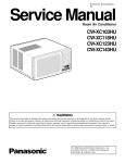
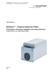
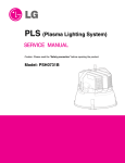
PLS (Plasma Lighting System)
SERVICE MANUAL
Caution: Please read the “Safety precaution” before repairing the product.
Model: PSF1032A
Contents
1. Safety precaution ....................................................................................... 3
2. Product specification ................................................................................. 4
3. Exterior and name ...................................................................................... 5
4. Installation environment and method
■ PSF1032A installation environment guide ............................................ 6
■ Installation method and example ..................................................... 7~10
■ Example of incorrect installation .......................................................... 11
5. Operating principle and description
■ Block diagram .................................................................................... 12
■ PLS operating order .......................................................................... 13
■ Drive PCB diagram ...................................................................... 14~15
6. Troubleshooting
■ Error mode and action ........................................................................16
■ Error check mode and resolution
..................................................... 17
■ Error cancelation method .................................................................. 17
7. Disassembly diagram
............................................................................ 18
8. Replacement parts list ........................................................................... 19
2
1. Safety precaution
Caution: PLS product operates at high temperature and generates high voltage at the power
supply. Because it can cause serious injury such as electric shock or burn when
handling the product, please read follow the check order as shown below.
1. Installation and repair/check precaution
• Never disassemble the product unless done by specialized service technician.
(It can cause safety accidents such as electric shock or fire.)
• When servicing the product, unplug the power cord and make sure that the power is completely disconnected.
• When repairing or checking the PLS product immediately after operating the product, wait until the system is
cooled sufficiently.
• If PLS is abnormally turned off, always handle the product after disconnecting the power.
(It can cause electric shock or leakage of electromagnetic wave.)
• If the product is wet, always wipe out the moisture before working on the product.
• Clean the front cover glass periodically to maintain the illumination.
• Do not directly look into the bulb while the product is operating. The strong light can cause visual defect to the
eye.
2. Check grounding
• Before working on the product, check whether the product is grounded and make sure to ground the product if not
done so.
3. Electricity connection test for troubleshooting
• Install the repair jib on flat floor and mount the PLS product, and then connect the power.
• Do not leave any flammable material around the product and keep a safe distance as defective parts can heat up
to start a fire.
• Because the heat can be concentrated on the illuminated area, keep more than 30cm of distance from flammable
material or from the floor.
4. Check and replacement method for electric parts
• When checking the electric part immediately after disconnecting the power, discharge the high voltage part of the
PCB before doing so. (High voltage capacitor and lightron high voltage charge can cause electric shock.)
• When the electricity is connected, never touch the power circuit.
(High voltage of DC 3500V~4000V is generated on the high voltage part.)
• Do not use parts that do not comply with the specification. (It can cause an error.)
• When there is an issue with the power circuit, it is difficult to replace the individual parts installed on the PCB.
Therefore replace the entire power supply.
※ Caution: When using devices such as tester to check for error, always disconnect the electricity before using.
5. Electricity/Operation test after repair
• Never operate the product when it is not fully assembled such as lightron disassembled and waveguide separated
etc. It can cause strong leakage of electromagnetic wave.
• Connect the electricity in normal condition after sufficiently checking the electric/mechanical assembly of parts,
wiring condition and grounding connection etc.
6. Correct installation and grounding check
• After repairing the PLS product, clean the exterior and interior of the main unit and check the grounding condition.
And then install the product in its original position.
3
2. Product specification
SPECIFICATION
No.
CLASSIFICATION
1
Rated voltage (AC)
Single phase 220-240 V / 50 Hz
2
Rated current (AC)
4.7A ± 5%
3
Power consumption
1,000W
4
High frequency output (Microwave)
450 W
5
High frequency
6
Lightron
7
Optical speed
8
Optical efficiency
85 lm/W
9
Color temperature
4,500 K 5,500 K 7,500 K
10
Color rendering index
80 Ra
11
Dimension (L x W x H)
L570 x W440 x H680 mm
12
Weight (kg)
Fuse
Thermostat
13
Safety
device
Abnormal voltage
detection
Thermistor
Input current check
14
Characteristics
2450 MHz ± 50 MHz
2M214.A03GPTF
85,000 lm
21 kg
Block overcurrent above specification: 250 V, 10 A
Prevent overheating of LTN: 130 ˚C / 70 ˚C
Over: 264V or above
Under: Block system when 176V or below
Prevent overheating of power supply module: 75 ˚C
Detect oscillation of lightron
• Optical spectrum near natural light (Comfortable lighting)
• Lighting speed of 20 seconds
• Long life with high optical speed and high color rendering
• Environment friendly lighting device with high energy efficiency
※ Above specification and safety circuit may change without separate notification.
4
3. Exterior and name
Cover, Front
Cover, Side
Cover, Back
Tilt, Swivel
Cable,
High Voltage
Power Cord
(Plug-less)
Power Supply
Cover, Top
Glass, Cover
Bolt,
Aiming Angle
Case, Upper
Case, Lower
5
4. Installation environment and method
▣ PSF1032A installation environment guide
[● : Can be installed, ▲ : Request for consultation, × : Cannot be installed]
Application
classification
Installation environment
PSF1032A
Temperature range of use (˚C)
-20 ~ +40 ˚C
Humidity range of use (%)
80% or less
Indoor installation (Fixed downward)
×
Plant
●
Indoor gym
●
Warehouse
●
High rise building (Indoor)
●
Large building (Indoor)
●
Square or play field
●
Park
●
Large bulletin board
●
Large wall
●
Bridge
●
Environment with high temperature and humidity
▲
Environment with use of gas
×
Area with vibration
▲
Area with metallic dust
▲
Operating time of 24 hours/day
▲
Operating time of 16 hours/day
●
Operating time of 10 hours/day
●
Operating time less than 10 hours/day
●
Area difficult for A/S
▲
Wireless LAN
●
Single phase 220V ± 15%
Input power condition
2.0 mm2 or above
Power wiring (mm /unit)
2
Wiring per switch
3 or less
Circuit breaker capacity (Per unit)
Power
supply
10A or above
Main wiring (mm )
2
–
- When wiring 2 units
3.5 mm or above
- When wiring 4 units
5.5 mm2 or above
- When wiring 6 units
8.0 mm2 or above
2
- When wiring more than 6 units
Request for consultation
To maintain safety of high voltage power and to prevent malfunction, connecting the grounding cable to
each PLS set.
※ Above conditions related to power must be complied. If changes are required, please contact LG for
consultation.
※
6
▣ Installation method and example
1) This model (PSF1032A) is designed to be installed outdoors and supports day to day water proofing.
2) To prevent the product from falling by wind or other external force, use the bolt and nut of M8 or above.
3) Be careful not to let other objects interfere with product from cooling and also be careful not to block the
inlet/outlet when installing the product.
4) Installing the product in an environment that exceeds the usable temperature and humidity can cause
unexpected issues. Therefore always consult with LG Electronics before installing the product.
5) Installing the product in locations where chemicals such as TCE series or chlorine gas are used or
locations where vibration is excessive can cause unexpected issues. Therefore always consult with LG
Electronics before installing the product.
6) When using the product in highly dusty area, the illumination can be reduced due to the dust. Therefore
periodically clean the product and do not install the product where metallic dust is generated.
7) Install at least 1m from the ground clearance distance must be maintained.
8) The mark means min. distance from PLS to lighted object when install the PLS, check the distance from
PLS on the optical axis of PLS.
3m
CAUTION
1. Follow regulations of government agency for technical standard and electric power company's guide
regarding regulations on equipment and wiring.
WARNING
• By the regulation and this installation guide, electric work using a specific circuit must
be done by certified electric technician. It can cause fire or electric shock if capacity of
power supply circuit is insufficient or faulty.
2. Do stated earth work when installing PLS
WARNING
• Do earthwork of PLS. Do not connect earth wire with gas pipe, water pipe, lightning
rod or telephone line. It can cause electric shock as it makes earthwork incomplete.
※ Product size
(Units : mm)
7
※ Power condition and switchboard configuration for PLS installation
• Because the power consumption per 1 set of PLS is high, the cross sectional area of the
switchboard must appropriately be applied, and for stable operation, one control switch must be
installed for each set.
• Grounding requires more than 3 grounding points and must be wired for safety purposes.
PLS switchboard
(When installing 6 sets)
MCCB
75A or
above
Apply 2.0 mm2
or above for
each line
Apply
14.0 mm2
or above
Recommended to
apply ELB, MS
capacity of 10A
* PLS is not equipped with a terminal block. For installation, please get professional assistance.
- Terminal Block Specification
(a) Rated Voltage: 250V or above
(b) Rated Power: 10A or above
(c) 3 way bolt fastening type
- After connecting power line to the terminal block, ensure that the power line makes secure
contact with fastening bolt or clamp and the power line is securely fastened.
WARNING
• After wiring power line to terminal box, check if the line touches tightening bolt or clamp or
is being forced.
• Use regulated electric wire so connecting part of terminal is knocked out by external force.
It can cause fire if connecting part is fixed tightly as it generates heat.
• Wire power line after ring terminal work. It can cause fire and failure of electric parts.
• Check Neutral status when installing main power
• Ending part of PLS has to be waterproof when connecting it to terminal.
Note)
MCCB: Molded Case Circuit Breaker
ELB: Earth Leakage Circuit Breaker
Use rate sensitivity current (Break current) of 30 [mA]
MS: Magnetic Switch (Used when applying GPS or auto flash device)
8
※ Lower Case and Base Plate size
Case Lower
– Refer to the dimension of the case below the power supply and fixate the product.
(Units : mm)
Inlet
231
70
40
400
110
10
59
Bolt/Nut connection
(Hole with width of 10mm)
252
13
Outlet
Base plate to fixate product (Separately manufactured)
– Considering the safety of the system and installation, it is recommended to manufacture the
base plate separately to fixate the product. Refer to the following drawing.
(Not included in the product)
– If the base plate is not required, install the product by considering the cooling path
(Inlet/Outlet) of the system.
255,0
30,0
80,0
30,0
80,0
50,0
(Units : mm)
30,0
400,0
30,0
80,0
12,0
▶ When manufacturing the base plate to fixate the
product, always use steel plate of L400xW272 (mm)
5T or above.
9
※ Installation example
Optical source
(LDM)
Bolt,
Aiming Angle
M8 Bolt
Power supply
(PSM)
Inlet
Outlet
Base plate to
fixate product
Base Plate
Spring
Washer
M8 Nut
• Install the product on even ground free from submersion.
• When adjusting the bolt (M12 bolt, aiming angle) to adjust the PLS angle, always use a spanner
and maintain torque of 40kgf.cm or above.
10
▣ Example of incorrect installation
※ Below shows the example of incorrect application/usage. Be careful with installation and usage
in the following cases as it can cause electric shock, injury, burn etc.
No.
Example of incorrect application and usage
Expected risk
1
When using with impact, such as product falling, applied on product
Fire/Electric shock
2
When using with switchboard below rated current capacity
Fire/Electric shock
3
When product is disassembled and reconfigured arbitrarily
Fire/Electric shock
4
When installing/using product without securing space to cool the product
5
When fixed/used loosely without considering the installation board, product weight/vibration etc.
6
When installing, repairing and checking the product in an environment where water can penetrate into the
product. This product can be used for underwater lighting (Underwater scenery, exploration, event usage etc.)
7
When using the PLS product without repairing after submersed under water
Fire/Electric shock
8
When using the product in condition with excessive power voltage variance (Above ±15%)
Fire/Electric shock
9
When using the product without grounding
Fire
Injury
Electric shock
Electric shock
10 When excessively bend the power cord or using damaged power cord
Fire/Electric shock
11 When inserting any pin, coin or metal wire into the internal/external hole on the case
Fire/Electric shock
12 When putting a cover on the exterior of the product for use without considering the suction inlet/exhaust outlet
Fire
13 When using the product with flammable material around the product
Fire/Electric shock
14 When disassembling while the product is operating
Fire/Electric shock
15 When repairing or disassembling the product by an unqualified technician
Fire/Electric shock
16 When using in environment where alien particles penetrate into the suction inlet/exhaust outlet
Fire
17 When cleaning or repairing the product while operating the product
Electric shock
18 When touching the power cord with wet hands
Electric shock
19 When using the product for purpose other than lighting (Heating food, drying clothe, heating etc.)
Fire/Electric shock
20 When moving the product by holding the part other than the main unit (Moving by holding the reflector etc.)
Injury
21 When moving the part without caution not considering the weight of the product
Injury
22 When not wearing any safety gear when contacting the hot part (Cover glass, reflector etc.)
Injury
23 When using the product near a heating device
Fire/Explosion
24 When installing and using the product near areas with risk of flooding
Electric shock
25 When cutting and using the power cord arbitrarily
Fire/Electric shock
26 When making body contact on the product when it is hot while operating or immediately after operating
27 When installing and using the product in areas not properly ventilated
28 When using underwater
Injury
Fire
Electric shock
11
5. Operating principle and description
▣ Block Diagram
12
▣ PLS operating order
13
▣ Drive PCB diagram
※ PSF1032A PCB ASSEMBLY INVERTER
P800 AC 220V input
LED700/701
DC/15V/24V power LED
P901
DC fan connector
P900
SYS, fan, bulb MTR connector
VR800 output volume control
P301
Ext. PGM loading terminal
LED 300 error display
S300 error cancel switch
P601 high voltage earth
terminal
P600 high voltage (4kV)
terminal
14
※ PSF1032A LED error display
LED error display
No. 1: Input voltage error
No. 2: BLDC error
No. 4: Input current error
No. 5: Inverter internal temperature error
15
6. Troubleshooting
▣ Error mode and action
* Caution: First, check whether the power cord is unplugged from the outlet and then check/repair
according to the safety precaution and procedure.
Error mode
Check point
Check method
Check whether the power Check for any issue on L, N,
cord and other internal
GND and internal wiring
wiring is done correctly
Does not
light up
initially
Action item 1
Action item 2
(If not resolved by action item 1)
Check wiring based
on installation
standard and internal
wiring
Check whether the fuse is Separate the noise filter box of Replace PSM (Power
disconnected
the power supply and visually Supply Module)
check whether the fuse is
disconnected
Check error check mode: Check the input power voltage
Flash error LED 1 time
Check error check mode: Check whether BLDC rotates
Flash error LED 2 times Check BLDC cable wiring
Replace bulb assembly
Check system power
consumption
If normal, replace the
bulb assembly
Replace generator
assembly
Connect the cable
Replace DC fan
Connect the cable
Replace DC fan
After checking the power
consumption using the
measuring device, check
whether it is normal
Check whether DC fan of Check system DC fan cable
LDM part is operating
normally
Check error check mode:
Lamp goes Flash error LED 5 times
off trying to
turn on
Check error check mode:
Flash error LED 1 time
Check whether PSM cooling
fan is operating and whether
there is any issue with wiring
Check input power voltage
Check resonator condition Check if the resonator is
crushed or have any holes
Check system power
Lamp is dark consumption
Connect the cable
Check the system power
consumption using the
measuring device
16
Replace LDM (Light
Drive Module)
Replace PSM
Replace generator
module
▣ Error check mode and resolution
Error
Code
Error display
1
Error LED on-and-off 1 time
(●
●
●→)
Line Voltage Error Check
(220V ± 15% or more)
Unstable input power voltage and
operation with overvoltage
2
Error LED on-and-off 2 times
(●●
●●
●●→)
BLDC FG Error Check
(Less Than BLDC 1,400 RPM)
Check whether BLDC is locked and
whether BLDC cable is connected
4
Error LED on-and-off 4 times
(●●●●
●●●●→)
Input Current Error Check
(Unstable lightron oscillation)
Check whether the lightron is operating
normally and whether the system fan is
operating
5
Error LED on-and-off 5 times
(●●●●● ●●●●●→)
P/Supply Inne Temperature
Error Check
Check whether the PSM cooling fan is
operating
Error detail (Check limit)
Check point
▣ Error cancelation method
Control PCB error
Cancel error using clear
switch
1. Turn on power line
2. Check error LED
3. Press the error clear switch for 2 seconds. (Wait until the flashing LED is turned off)
4. Wait 30 seconds after the power line is turned off. (Discharge fully)
5. Check for relighting
Cancel error using
power line
1. Turn on power line
2. Turn off power line between 3~5 seconds
3. Repeat 1~2 process 5 times.
4. Wait 30 seconds after the power line is turned off on the last 7th time.
(Discharge fully)
5. Check for relighting
17
7. Disassembly diagram
301
103
102
401
403
402
101
404
104
302
304
303
308
405
406
305
307
202
309
310
201
306
18
8. Replacement Parts List
DESCRIPTION
LOC NO. PART NO.
Generator Assembly, Microwave
101
AEC70519301 Guide Assembly, Wave
102
ADZ72910401 Generator Assembly, Microwave
103
MAZ62067401 Bracket, Fan
104
EAL31553601 Fan Module
EA
No.
Waveguide Assembly, PSF10
PSF1032A, 7500K
PRESS AL 1 Air Guide
4715K 2.95kRPM DC 24V
EA
EA
EA
EA
1
1
1
1
Power Supply Assembly
201
EBR62853901 PCB Assembly
202
EAL38070201 Fan Module
203
EAD60973001 Cable Assembly
NYX1k Inverter Assembly (BLDC & Filament Control)
4710KL-05W-B40, 2.5kRPM DC 24V
KR010816-01 2P Housing / Spade Terminal 1.21M 12Pin Black
EA
EA
EA
1
1
1
Cover Assembly
301
ACQ75452201
302
MBL62598101
303
MCK62733701
304
MCK62733801
305
3043Z-FB02A
306
3111300001A
307
3110Z-L006A
308
3550Z-T006A
309
MDS39999701
310
3550Z-F005A
PSF1032A
MOLD IIR PSF10 Cable Box
Casting ADC12 290 200 155
Casting ADC12 200 200 63
Flood900 SP
PSF09
AL Diecasting
AL Diecasting
Complex Plate & Waveguide
AL Diecasting
EA
EA
EA
EA
EA
EA
EA
EA
EA
EA
1
1
1
1
1
1
1
1
1
1
PSF1032A, 7500K
Sintering Quartz OD76
SUS, OETCK(DEUCH)
ALUMINUM5052 0.5t
SINTERING GLASS 370 320
Neo PSF10 10Deg
EA
EA
EA
EA
EA
EA
1
1
1
1
1
1
Cover Assembly, Side
Cap, Protector
Cover, Side
Cover, Rear
Supporter Assembly
Case Assembly
Case, Rear
Cover, Top
Gasket, Packing
Cover, Front
Generator Assembly, Optic & Guide Assembly, Optic
401
ABD72910201 Bulb Assembly, Motor
402
5018Z-L001A Mirror
403
4016Z-M001A Strap, Resonator
404
AKD72909201 Resonator Assembly
405
MCK63206601 Cover, Optic
406
3035300002B Reflector Assembly
SPECIFICATION
19
※ Service inquiry and contact
Tel : 1544-5472
Fax: 055-268-4585
Address : PLS Part
76, Seongsan-dong,
Changwon-city, Gyeongnam, Korea
P/No.:MFL62883503
October, 2010
Printed in Korea