1
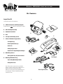
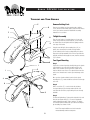
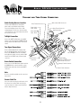
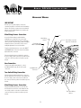
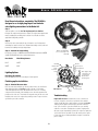
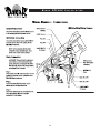
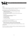
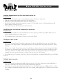
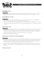
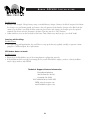
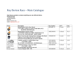
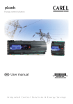
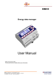
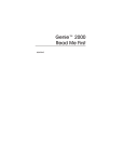
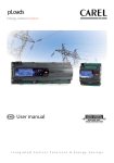
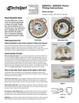
CRF450 DU
AL
SP
ORT
KI
T
IN
STALLATION
IN
STRUCTIO N S
HO
CRF450 IN
NDA
STALLATION
KIT CONTENTS
Inspect Your Kit
Your kit will include the following items
A. CRF450 Instructions and Wiring Diagrams
Read through the entire instruction manual before starting.
B.
Dakar Headlight Assembly
C.
Handlebar Turn Switch
D.
Horn
E.
Tail Light and Mounting Screws
F.
Universal Hardware Bag (Contents)
A
B
D
E
-Turn Signals (2)
-Brake Light Switches (2)
C
-Cable Ties
-Wiring Diagram Label
-Round Plastic Signal Alignment Wedges
G.
F
Main Wiring Harness
-Note: Ignition Keys Zip Tied to Harness
H
Turn Signals
H. Mounting Kit Hardware Bag
-Triple Clamp Mounting Brackets
G
-Kit Specific Pieces
Note: Please take a moment to become familiar
with the contents of the kit. Due to slight variances
between motorcycle models, there may be
differences in the instruction manual drawings and
the actual parts. The basic installation procedure
remains the same.
Brake Light Switches
1.
HO
CRF450 IN
NDA
STALLATION
HEADLIGHT UNIT SUB-ASSEMBLY
Getting Started
Horn Mounting Hole
C
Remove and retain four (4) retaining screws, holding the
headlight numberplate to the Dakar unit. Then, unplug the main
wiring harness, turn switch wiring harness, headlight and horn
wiring connectors from the Dakar unit.
A
Attach The Horn
The horn may aread be installed on your kit, if not, the horn has
a nut with a washer screwed on the back. Remove and retain the
nut and washer. Locate the horn’s threaded stud on the outside
of the Dakar unit and into the horn mounting hole in the Dakar
unit. Fasten with previouslt removed washer and nut. (Be sure to
tighten securely without stripping)
B
Mounting Brackets
Attach headlight mounting brackets ( A ) with two screws ( B ) on
each side. Tighten screws securely into the Dakar headlight unit
( C ) without stripping.
Note: Bracket shown in illustration may differ from pieces in your
kit. However, the installation will remain the same.
Installing The Dakar Headlight Unit
A
Step 1
Remove and retain existing top triple clamp bolts ( D ). Carefully
slide brackets into position and fasten with existing bolts as
shown.
D
Note: Headlight assembly omitted for clarity.
2.
HO
NDA
CRF450 IN
STALLATION
TURN SWITCH INSTALLATION
Remove Existing Kill Switch
Step 1
Using a small phillips head screwdriver, loosen the locking screw
( B ) on the kill switch ( C ). Remove any cable ties and unplug kill
switch from existing wiring.
Step 2
Loosen clutch cable perch ( D ) and move inboard about 1/2
inch.
Install Turn Switch
D
A
Step 1
Open and wrap the new turn switch ( E ) around handlebar and
securely fasten with two screws ( F ) as shown.
C
B
Step 2
Route turn switch wiring down and along handle bar behind
Dakar headlight unit and in through frame cable guide. Secure
switch wiring to handlebars with one cable tie. For more
information, please refer to the Cable Routing Diagram.
E
F
Cable Tie
3.
HO
NDA
CRF450 IN
STALLATION
BRAKE LIGHT SWITCHES
Check Thread
Pitch Before
Installing
Front Brake Light
WARNING
Bleed front and rear brakes according to instructions
provided in your owners or service manual. This must be
performed in order for proper brake operation. Failure to do
so may result in brake failure
WARNING: Check the thread pitch on your
banjo bolts
Step 1
Place a drop cloth or rag under the front brake and bike to catch
any fluids. Loosen and retain banjo bolt on master cylinder.
Make sure the thread pitch on your stock banjo bolts
match the replacement versions provided in the kit. More
than likley they will match. Some manufactures have
changed the stock design requirement which is why it
necessary to check. If your parts do not match up, stop
the installation and give us a call. We’ll send replacement
parts to you!
Master
Cylinder
Step 2
Insert brake light switch into position and fasten with banjo bolt
on top of soft washer, hydraulic line and second soft washer.
Securely fasten banjo bolt without stripping.
Brake Light
Cable
Step 3
Route the front brake light switch wiring along the lower portion
of the handlebar towards the center of the triple clamps. Fasten
wiring to the handlebar with a cable tie.
Brake Pedal Light
Step 1
Place a drop cloth or rag under the rear brake and bike to catch
any brake fluid. Remove the screws and guard providing access
to the rear brake master cylinder.
Banjo Bolt
Soft Washers
Brake Light
Cable
You must temporarily reinstall the screws that attach the master
cylinder to the frame to prevent damage to the master cylinder or
Banjo bolt threads. After the master cylinder is secure, carefully
remove the existing banjo bolt. Remove and retain the mounting
screws.
Banjo Bolt
Note: Some bikes allow access to the master cylinder without
removing a cover or guard.
Banjo Bolt
Step 2
Insert brake light switch into position and fasten with banjo bolt
on top of soft washer, hydraulic line and second soft washer.
Securely fasten banjo bolt without stripping. Reinstall guard with
screws
Soft Washers
Master Cylinder
Fastening Screw
4.
Step 3
Route the rear brake light switch wiring up the sub-frame spar
and following behind the airbox up towards the back of the frame.
The wiring should meet up next to the main wiring harness tail
light and turn signal connection point.
HO
TAILLIGHT
CRF450 IN
NDA
AND
STALLATION
TURN SIGNALS
Remove Existing Parts
E
D
F
Remove your existing seat, front number plate, radiator
covers, fuel tank, side number plates and rear fender. Please
refer to your owners manual for detailed dis-assembly
instructions for each item.
F
B
F
C
A
Taillight Assembly
Place the rear fender ( A ) upside down on a clean work
surface and position the rear tail light ( B ) on the inside of
the fender. Note: the tail light should rest slightly under the
rear edge of the fender.
Using the rear tail light’s four mounting holes ( C ) as
guides, trace around each hole with a felt tip marker
on the underside of the fender creating drill hole locations.
Remove the tail light and drill 1/4 inch holes. Reposition the
tail light, and fasten with supplied screws, washers and nuts
( D ) as shown.
D
I
E
I
Turn Signal Mounting
Step 1
Position the rear turn signals by visually lining up the signals
( G ) behind the rear seat, when its attached to the subframe. Care should be observed to insure signals do not
interfere with the rear silencer. The signals must mount free
and clear of exhaust heat in order to prevent damage to the
signal.
Once you have found a suitable location for the signal
mounting hole ( E ), mark and drill one 3/8 inch hole through
each side.
J
K
G
Step 2
Drill a second hole ( F ) on each fender side, allowing
the signal wiring to pass through underneath the rear
seat. Note: On some bikes, signal wiring holes are already
available.
Step 3
Feed the tail light wiring ( I ) through the right side hole and
then the turn signal wiring ( J ). Secure turn signal with
supplied alignment wedges, washer and nut ( H ). Attach
second turn signal following same procedure and complete
by reinstalling rear fender on bike.
H
Note: There may be differences in the instruction
manual drawings and the actual parts.
5.
HO
TAILLIGHT
Cable Routing Harness Location
Feed the main wiring harness through the
frame cable loop behind the triple clamps.
For more information, please refer to cable
routing diagram. For reference, stick the wiring
connection decal on the rear fender, below where
the seat will cover it up.
AND
NDA
CRF450 IN
STALLATION
TURN SIGNAL CONNECTION
Violet Female Connector
Brake Switch
Male - Black
White / Green Male Connector
Gray Female Connector
Right Turn Signal
Brake Switch
Male - Black
Taillight Connection
Connect the WHITE tail light male to the GRAY
female connector. Connect the BROWN tail light
male ground to the BLACK female connector as
shown.
Turn Signal Connections
Connect both BLACK tail turn signal grounds
into the dual BLACK female ground connector.
Connect the ORANGE female into the BLACK
male (right turn signal) connector, and the PINK
female, into the BLACK male, (left turn signal)
connector.
Brake Switch Connection
Cable
Ties
Left Turn Signal
Brown Female
Connector
Pink Female Connector
Black Female Connector
Orange Female Connector
Connect one of the BLACK brake switch male into
the BROWN female connector and the second
BLACK brake switch male into the dual VIOLET
connector.
Black Female Connector
Note
Be sure to carefully and fully seat the connectors
into position.
Secure Cable Ties
Use a few cable ties along the sub frame to hold
the harness into position. Make sure that you
secure the harness to frame areas that will not
bind or crimp the harness.
6.
HO
CRF450 IN
NDA
STALLATION
HEADLIGHT WIRING
I M P O RTA N T
We have gone to great lengths to ensure the
seamless integration of each bike model and wiring
harness. Please take a moment to become familiar
with the specific wiring diagram of your make and
model of motorcycle.
Main Wiring Harness Connection
Access the Dakar wiring located behind the
headlight, by loosening two lower screws and
remove two top inboard screws. This is required in
order to provide enough freeplay to tilt the headlight
forward for harness connections. Please refer to
headlight adjustment for more information.
Horn
Main Wiring
Harness
Horn wiring connection
plugs into circuit board
Front Brake Light
VIOLET and BROWN
From the main wiring harness, connect the VIOLET
and BROWN female connectors into the front brake
light switch male connectors.
Plug-in main wiring harness (right side) connector.
Be sure to fully seat the connection. You will hear the
connector “click” into position on both the top and
bottom.
Horn Connection
From the turn switch wiring harness, connect
the PINK and BLUE leads, into the horn spade
connectors.
Headlight Cable
Connector
Turn Switch Wiring Connection
Plug-in main turn switch wiring harness connector
into the right side block connector on the Dakar unit.
Be sure to fully seat the connection. You will hear
the connector click into position on both the top and
bottom.
Main Wiring Harness Connection
Plug-in main Main wiring harness connector into
the left side block connector on the Dakar unit. Be
sure to fully seat the connection. You will hear the
connector click into position on both the top and
bottom.
Turn Switch Wiring
Harness
7.
HO
NDA
CRF450 IN
STALLATION
Read these instructions completely. The ESL950 is
designed as a straight plug-in part and includes
extra lighting connections to the Dakar kit.
Step 1
Take the ignition cover off. Are The Replacement Parts Similar?
Compare the replacement part to the original. The replacement part should
match, including the mounting hole locations. If not: Double check the
application listing with your bike.
Step 2
Unscrew the stock stator and pick-up coil from the case. Pull grommet
and wiring free and clear from case. Retain all mounting screws, bolts and
brackets for installing new high output stator.
NOTE: 2 YELLOW Wires
are for connecting to the
Dakar Kit
Step 3 - Connect the stator wiring
Connect the Pick-up coil GREEN and BLUE/YELLOW leads into the GREEN
and BLUE/YELLOW leads in the main wiring harness.
New Stator
Bike Wiring Harness
BLUE
WHITE
WHITE
BLUE
CRF High
Output Stator
Bracket
Pick-Up Coil
Fastening Bolt
Stator
Fastening
Screw
Lighting Options
Note: Apply locking
compound to all
screw and bolt
threads when
fastening parts.
Dual Sport Kit Lighting:
Both YELLOW wires are for connecting to a Dual Sport Kit
Finishing up the installation
Step 4 - Reinstall the new stator
Place the new stator and pick-up coil into position in the case and fasten
with existing brackets and existing screws as shown . If your stator
came with replacement screws, discard them. Be sure to use a locking
compound on the threads of all mounting screws. Insert the grommet into
position on the side case. Then install a new gasket onto the side case and
install the side case to the engine using existing screws. Torque screws as
specified in your service manual.
Grommet
Pick-Up Coil
CRF Sidecase
Gasket
Troubleshooting
Engine will not start: Sometimes the source coil wires are
reversed. Swap the connections, resolder the wires and the
engine should start. If the engine still does not start, and before
calling technical support at ElectroSport, preform a few basic
tests: 1) Re-check the connections. Make sure you carefully
solder the connections. Twisting wires together or taping wires
will cause engine inoperability. 2) Check the engine for spark and
3) Is fresh fuel in the gas tank? If you still cannot get the engine
to start, have all your testing information ready for a technician
prior to calling.
8.
HO
NDA
9.
CRF450 IN
STALLATION
HO
CRF450 IN
NDA
STALLATION
CDI RELOCATION OPTION 1
Remove existing CDI
Carefully remove existing bolts, CDI unit, and CDI
mounting bracket from frame. Once the CDI is free,
unplug the main connection from the CDI unit.
Existing CDI
Locate the mounting bracket
Existing CDI
rubber sleeve
There are two options for relocation of the CDI
mounting bracket. One is inside of the airbox or
option 2 is shown on the next page, near the radiator
Step 1
Start by taking the mounting bracket and locate
inside the airbox, so that the CDI will attach below
the top of the airbox, with the main connection plug
facing horizontal towards the left side of the bike.
Existing CDI bracket mounting bolts
Existing CDI
mounting bracket
Once a location has been selected, use the mounting
bracket as a guide and mark the two hold locations.
Note: These are the holes that previously were used
to attach the bracket to the steering tube on the front
of the frame.
Existing CDI
RED/BLACK
Dakar main
wiring harness
CDI power lead
jumper
CDI power
RED/BLACK
Existing
GREEN ground
Ignition ground
GREEN
Existing CDI
rubber sleeve
Existing CDI
mounting bracket
CDI
Step 2
From the inside of the rear fender, attach two bolts,
securing the bracket to the inside of the airbox. Press
the rubber CDI sleeve into the tabs on the bracket
until the tabs poke through the rubber slots on each
side. Double check the rubber sleeve making sure it
is firmly seated to the bracket.
Route the CDI wire
Step 1
Feed the CDI wire through the left side sub frame,
next to the top shock mount and back along the side
of the airbox ending up with the connection plug
locating into the CDI as shown.
Step 2
Insert the CDI into the rubber sleeve.
Existing CDI
Bracket Bolts
Stator Wiring
New CDI mounting
bracket holes
10.
Secure the ground and power leads
Step 1
Route the ignition GREEN ground lead up the left side
under the subframe and in front of the airbox. Drill
a small pilot hole into the subframe and attach the
ground wire as shown.
Step 2
Connect the RED/BLACK ignition power jumper wire
to the Dakar main wiring harness and connect the
RED/BLACK CDI power lead to the ignition coil.
HO
NDA
CRF450 IN
STALLATION
CDI RELOCATION OPTION 2
CDI Mounting Option 2
Existing CDI
Mounting Bracket
After removing the CDI you will need to remove
the mounting bracket from the headtube on the
frame.
Fasten an ADEL style U-bracket
ADEL Clamp
Take one ADEL bracket and wrap it around the
frame spar that is located behind the radiator.
Fasten one bolt on the top and bottom
sndwiching the ADEL bracket around the frame
spar and into the existing CDI mounting bracket.
ADEL clampa are available at most hareware
stores, such as Home Depot, Lowes, or ACE.
11.
Existing CDI
HO
NDA
CRF450 IN
STALLATION
HEADLIGHT BEAM ANGLE ADJUSTMENT
Attaching The Headlight
A
After the wiring harness has been securely fastened and the
complete system has been tested, you can now tilt the top of
the headlight into the riding position and fasten the two inboard
screws ( A ) as shown. Complete the assembly by tightening the
lower two screws ( B ).
Accessing the wiring behind the headlight
When accessing the Dakar wiring located behind the headlight,
you must loosen the two lower screws ( B ) and remove the
two top screws ( A ). This is required in order to provide enough
clearance while tilting the headlight forward.
B E F O R E RIDING YOUR BIKE
Ignition Key
The Dakar Dual Sport Kit features a security key designed for
theft prevention and unauthorized operation of the motorcycle. To
start the motorcycle, rotate the key to the ON position as shown.
IMPORTANT: Do not leave the headlight on without the
engine running. It could cause damage to the battery. We
also suggest turning up the idle speed slightly to increase
system voltage while the engine is at idle.
B
The key is designed only as a means to disable operation of the
motorcycle. Use the turn signal kill switch to shut the motorcycle
off. Leaving the key in the ON position will drain the battery,
so be sure to turn the switch to the OFF position while leaving
the bike unattended. Now start your bike up and go show your
friends!
Key OFF Position
Key ON Position
12.
DMV DU
AL
SP
ORT
RE
GISTRATION
OV
E R V I E W
Overview
Vehicle registration policies in most states typically allow conversion of an off-road only title into a street title or
in some states a designated "Dual Registration." To register a dirt bike for street use, it must be equipped with the
necessary lighting and other equipment required by your state's vehicle code.
Every state requires what is called “The Federal Minimum Requirement” which consists of:
• Headlight with a high and low beam
• Headlight indicator light visible to the operator to show when the high beam is operating
• Horn - Some states mandate an electric horn
• Battery powered taillight and brake light which must operate for 20 minutes on battery power alone
• Rear view mirror
• Turn signals for motorcycles manufactured after 1/1/73 (Most States)
• Some states require speedometers and odometer’s
• Tires should be DOT approved
• Lights should be DOT approved
• Fuel tank should be DOT approved*
*
Even though the Federal Motor Vehicle Safety Standard specifies steel gas tanks for street motorcycles,
most states will not enforce this for converted dirt bikes
Registration procedures vary from state to state but typically involve:
• Signing two ”Statement of facts” certifying that your bike meets state/federal standards.
• Bringing the bike to the DMV or (AAA Insurance Office) for an inspection for proper lighting
• Once the paper work and inspection are complete the final step is to exchange your off-road title for a street title
Exchanging your title
Most states have a "Dual Registration Form" You should be able to download this form from your states DMV
over the internet or filling it out at your DMV office. Then pay the transfer fee and obtain your registration, put
the plate on your bike and go show your friends!
13.
HO
NDA
CRF450 IN
STALLATION
Nothing Happens When You Turn the Power Switch On
Possible Causes
• Fuse is blown. Check for bare wire or terminal shorting against the frame or another wire.
• Multi-pin connector not properly connected to the circuit board.
• Poor battery connection. Make sure the connectors are fully seated.
• Battery is flat. Measure voltage with voltmeter, or connect a 12 volt light across it. A fully charged battery will
measure between 12.9 and 13.2 volts.
• Poor connection at the blue wire junction above the shock.
Headlight does not work on high beam or low beam:
Possible Causes
• Check the bulb. Usually one of the bulb filaments is bad, so replacing it will fix the problem. Make sure you
replace the bulb with the exact same wattage.
• The handlebar switch is dirty inside. Clean it out with some WD40.
Headlight is dim at idle:
Possible Causes
• Increase the idle speed a little. Dual sport setups work a lot better is the idle speed is a bit "on the high side".
This is due to the design of most of the lighting /charging coils, which really start putting out power at around
1200 rpm.
• Battery is not charged. Charge battery using a standard battery charger. Connect the black (negative) lead from
the charger to a good frame ground, and connect the red (positive) lead from the charger to the blue lead that
connects to the horn. (just slide the blue connector sleeve back, and connect the charger up to the exposed
terminal) You do not need to disconnect the horn. Turn key switch to “ON” Position.
• Check bulb wattage. Certain kits come with a lower wattage bulb than a standard H4 bulb. Electrex has all bulbs
in stock.
Taillight does not work:
Possible Causes
• Check the bulb. Due to vibration the bulb could have gone out. Check the connections in the bulb holder as
well, water could oxidize the contacts, preventing the bulb from coming on.
• Check the connections, especially the ground under the seat. You'll find a gray wire (taillight positive), a black
wire (taillight and brakelight ground) and a violet wire (=purple, brake light positive). Check these connections
carefully.
14.
HO
NDA
CRF450 IN
STALLATION
Brake light stays on:
Possible Causes
• unplug the brake light switches one by one. If one of the switches is bad, it will close its contacts and leave the
brake light on. The brake light switch that makes the brake light turn off as soon as you unplug it, is bad.
Brake light does not work:
Possible Causes
• Check the bulb. Due to vibration the bulb could have gone out. Check the connections in the bulb holder as
well, water could oxidize the contacts, preventing the bulb from coming on.
• Check the connections, especially the ground under the seat. You'll find a gray wire (taillight positive), a black
wire (taillight and brakelight ground) and a violet wire (=purple, brake light positive). Check these connections
carefully.
Blinkers don't work:
Possible Causes
• Battery is not charged. Charge battery using a standard battery charger. Connect the black (negative) lead from
the charger to a good frame ground, and connect the red (positive) lead from the charger to the blue lead that
connects to the horn. (just slide the blue connector sleeve back, and connect the charger up to the exposed
terminal) You do not need to disconnect the horn. Turn key switch to “ON” Position.
• flasher relay is bad. Replace with new one.
Blinkers don't work at idle, or flash intermittently:
Possible Causes
• Battery is not charged. Charge battery using a standard battery charger. Connect the black (negative) lead from
the charger to a good frame ground, and connect the red (positive) lead from the charger to the blue lead that
connects to the horn. (just slide the blue connector sleeve back, and connect the charger up to the exposed
terminal) You do not need to disconnect the horn. Turn key switch to “ON” Position.
• increase the idle speed a little. Dual sport setups work a lot better is the idle speed is a bit "on the high side".
This is due to the design of most of the lighting /charging coils, which really start putting out power at around
1200 rpm.
Horn doesn't work:
15.
HO
NDA
CRF450 IN
STALLATION
Possible Causes
• Battery is not charged. Charge battery using a standard battery charger. Connect the black (negative) lead from
the charger to a good frame ground, and connect the red (positive) lead from the charger to the blue lead that
connects to the horn. (just slide the blue connector sleeve back, and connect the charger up to the exposed
terminal) You do not need to disconnect the horn. Turn key switch to “ON” Position.
• Adjust small set screw on the back side of the horn. Turn it both ways until you get a nice loud "honk'
Lost key while riding:
Possible Causes
• The Dakar setup will perform fine, but you'll have to top up the battery regularly (weekly) to prevent it from
going flat. Call ElectroSport for a replacement.
Kill button does not work:
Possible Causes
• Ensure that the black/white wire of the wiring harness is plugged in correctly.
• If the kill button does not work, but turning the key switch does kill the engine, you have a dirty handlebar
switch. Spray inside it with WD40.
Technical Support Contact Information
ElectroSport Industires
3803 Oceanic Dr. Ste 201
Oceanside CA 92056
PH: 760-842-8300 (9-5 M-F PST)
WEB: www.electrosport.com
email: [email protected]
16.