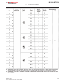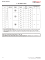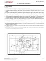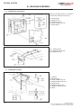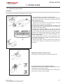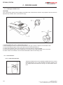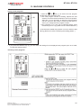
1
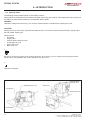
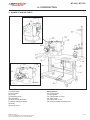
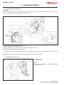
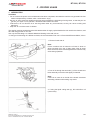
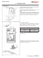
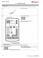
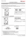
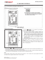
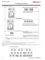
MODEL BT-3200
BT-2700
BAR - TACKING MACHINE
BUTTON - SEWING MACHINE
PARTS AND SERVICE MANUAL
MACHINE SERIAL No:
PART NUMBER
97.5300.0.000
This manual is valid from the machine Serial No.:
T530001
AMF is trademark of AMF Group, Inc.
10 / 2014
LIMITED WARRANTY ON NEW AMF REECE EQUIPMENT
Warranty provisions:
A ninety (90) day limited service labor warranty to correct defects in installation, workmanship, or material without charge for labor. This portion of the warranty applies to machines sold as ”installed” only.
A one (1) year limited material warranty on major component parts to replace materials with defects. Any
new part believed defective must be returned freight prepaid to AMF Reece, Inc. for inspection. If, upon
inspection, the part or material is determined to be defective, AMF Reece, Inc. will replace it without
charge to the customer for parts or material.
Service labor warranty period shall begin on the completed installation date. Material warranty shall begin on the date the equipment is shipped from AMF Reece, Inc.
Exclusions:
Excluded from both service labor warranty and material warranty are: (1) Consumable parts which
would be normally considered replaceable in day-to-day operations. These include parts such as needles, knives, loopers and spreaders. (2) Normal adjustment and routine maintenance. This is the sole
responsibility of the customer. (3) Cleaning and lubrication of equipment. (4) Parts found to be altered,
broken or damaged due to neglect or improper installation or application. (5) Damage caused by the use
of non-Genuine AMF Reece parts. (6) Shipping or delivery charges.
There is no service labor warranty for machines sold as ”uninstalled”.
Equipment installed without the assistance of a certified technician (either an AMF Reece Employee,
a Certified Contractor, or that of an Authorized Distributor) will have the limited material warranty only.
Only the defective material will be covered. Any charges associated with the use of an AMF Reece
Technician or that of a Distributor to replace the defective part will be the customer’s responsibility.
NO OTHER WARRANTY, EXPRESS OR IMPLIED, AS TO DESCRIPTION, QUALITY, MERCHANTABILITY, and FITNESS FOR A PARTICULAR PURPOSE, OR ANY OTHER MATTER IS GIVEN BY SELLER
OR SELLER’S AGENT IN CONNECTION HEREWITH. UNDER NO CIRCUMSTANCES SHALL SELLER OR SELLER’S AGENT BE LIABLE FOR LOSS OF PROFITS OR ANY OTHER DIRECT OR INDIRECT COSTS, EXPENSES, LOSSES OR DAMAGES ARISING OUT OF DEFECTS IN OR FAILURE
OF THE EQUIPMENT OR ANY PART THEREOF.
WHAT TO DO IF THERE IS A QUESTION REGARDING WARRANTY
If a machine is purchased through an authorized AMF Reece, Inc. distributor, warranty questions should
be first directed to that distributor. However, the satisfaction and goodwill of our customers are of primary concern to AMF Reece, Inc. In the event that a warranty matter is not handled to your satisfaction,
please contact AMF Reece office:
Prostejov, Czech Republic
Phone: (+420) 582-309-275
Fax: (+420) 582-360-608
e-mail: [email protected]
Warranty Registration Card
(Please Fax or Mail immediately after installation)
Note: All Warranty Claims Void, unless Registration Card on file at AMF Reece HQ
Machine model number:
(S101, S100, S104, S105, S311, Decostitch, S4000, EBS Mark II, etc)
Manufacturer‘s serial or production number:
Installation Site Information:
Customer‘s Name:
Customer‘s Mailing Address:
Customer‘s Telephone Number:
Supervising Mechanic‘s or Technician‘s Name:
Signature of Supervising Technician:
AMF Reece Technician‘s Name:
AMF Reece Technician‘s Signature:
Type of garment produced at this location?
Average Daily Production Expected from this machine?
(number of buttonholes, jackets sewn, pants produced, buttons sewn, etc)
Any special requirements required at this location?
What other AMF Reece Machines are at this location?
How can we serve you better?
BT-3200, BT-2700
TABLE OF CONTENTS
A-INTRODUCTION
1. BASIC INFORMATION.......................................................................................................................1-1
2. SAFETY INSTRUCTIONS..................................................................................................................1-2
2.1. Environmental requirements............................................................................................................1-2
2.2. Installation........................................................................................................................................1-2
2.3. Sewing.............................................................................................................................................1-3
2.4. Cleaning...........................................................................................................................................1-3
2.5. Maintenance and inspection............................................................................................................1-3
2.6. Warning labels.................................................................................................................................1-4
3. NAMES OF MAJOR PARTS...............................................................................................................1-5
4. SPECIFICATIONS..............................................................................................................................1-6
4.1. Machine specifications.....................................................................................................................1-6
4.2. Program list (BT-3200).....................................................................................................................1-7
4.3. Program list (BT-2700)...................................................................................................................1-12
B-MACHINE ASSEMBLY
1. INSTALLATION.................................................................................................................................1-15
1.1. Table processing diagram .............................................................................................................1-15
1.2. Installing the control box................................................................................................................1-16
1.3. Installing the oil pan.......................................................................................................................1-16
1.4. Installing the machine head...........................................................................................................1-17
1.5. Installing the operation panel.........................................................................................................1-18
1.6. Installing the treadle unit................................................................................................................1-18
1.7. Installing the cotton stand..............................................................................................................1-19
1.8. Installing the button tray (BT-2700)................................................................................................1-19
1.9. Installing the eye guard..................................................................................................................1-19
1.10. Connecting the cords...................................................................................................................1-20
1.11. Connecting the ground wire.........................................................................................................1-22
1.12. Installing the back cover..............................................................................................................1-22
C-PROPER USAGE
1. LUBRICATION..................................................................................................................................1-23
2. STARTING UP..................................................................................................................................1-24
3. PREPARATION BEFORE SEWING ................................................................................................1-25
3.1. Installing the needle ......................................................................................................................1-25
3.2. Threading the upper thread ..........................................................................................................1-25
3.3. Winding the lower thread...............................................................................................................1-27
3.4. Installing the bobbin case .............................................................................................................1-28
3.5. Thread tension ..............................................................................................................................1-28
3.5.1. Lower thread tension .................................................................................................................1-28
3.5.2. Upper thread tension .................................................................................................................1-29
3.6. Thread nipper device ....................................................................................................................1-30
3.7. Inserting the button BT-2700.........................................................................................................1-32
3.8. Adjusting the button clamp BT-2700..............................................................................................1-32
3.9. Installing the accessory spring BT-2700........................................................................................1-32
D-MACHINE CONTROLS
1. USING THE OPERATION PANEL (BASIC OPERATIONS) ............................................................1-33
1.1. Name and function of each operation panel item .........................................................................1-33
1.2. Setting the program number..........................................................................................................1-34
1.3. Setting the X-scale and Y-scale ....................................................................................................1-34
1.4. Setting the sewing speed ..............................................................................................................1-34
1.5. Checking the sewing pattern (BT-3200)........................................................................................1-35
1.6. Checking the sewing pattern (BT-2700)........................................................................................1-36
1.7. Adjusting the work clamp / button clamp lift amount .....................................................................1-37
Released: 10/2014
E-mail: [email protected]; webside: amfreece.com
Phone: +420 582 309 146; Fax: +420 582 360 606
BT-3200, BT-2700
TABLE OF CONTENTS
2. USING THE OPERATION PANEL (ADVANCED OPERATIONS) ....................................................1-38
2.1. List of advanced functions ............................................................................................................1-38
2.2. Setting memory switches...............................................................................................................1-39
2.3. List of memory switches................................................................................................................1-40
2.4. Using the lower thread counter .....................................................................................................1-41
2.5. Using the production counter ........................................................................................................1-42
2.6. Using user programs ....................................................................................................................1-43
2.7. Using cycle programs ...................................................................................................................1-46
2.8. Direct selection .............................................................................................................................1-48
2.9. Loading additional data .................................................................................................................1-49
2.10. Using CF cards ...........................................................................................................................1-49
3. SEWING .................................................................................................................. 1-50
E-MACHINE MAINTENANCE
1. MAINTENANCE ...............................................................................................................................1-51
1.1. Cleaning the rotary hook ...............................................................................................................1-51
1.2. Cleaning the control box air inlet ports .........................................................................................1-52
1.3. Draining the oil ..............................................................................................................................1-52
1.4. Cleaning the eye guard .................................................................................................................1-52
1.5. Checking the needle .....................................................................................................................1-52
1.6. Lubrication ....................................................................................................................................1-52
1.7. Applying grease (When “GREASEUP” appears) ..........................................................................1-53
2. GREASE APPLICATION LOCATIONS.............................................................................................1-55
3. RESETTING THE GREASE UP COUNTER....................................................................................1-55
Released: 10/2014
E-mail: [email protected]; webside: amfreece.com
Phone: +420 582 309 146; Fax: +420 582 360 606
BT-3200, BT-2700
A - INTRODUCTION
1. BASIC INFORMATION
Thank you very much for buying an AMF Reece sewing machine. Before using your new machine, please read the
safety instructions below and explanations given in this manual.
With industrial sewing machines, it is normal to carry out work while positioned directly in front of moving parts such
as the needle and thread take-up lever, and consequently there is always a danger of injury that can be caused by
these parts. Follow the instructions from training personnel and instructors regarding safe and correct operation
before operating the machine so that you will know how to use it correctly.
This manual refers to the following lockstitch sewing machines:
A) BT-3200 bar-tacking machine, intended for sewing of bartacks with fully variable pattern on mediumand heavy-weight fabric. The following three basic models are available:
BT-3200 - 001 (53.0000.0.001) for medium-weight garment
BT-3200 - 003 (53.0000.0.003) for heavy-weight garment
BT-3200 - 005 (53.0000.0.005) for light-weight garment
B) BT-2700 button-sewing machine, intended for sewing of buttons using lockstitch. The following model is available:
BT-2700 (53.0000.0.011)
Safety mechanisms protect both, operators and the machine, and respect valid safety and hygiene provisions for
usual technological usage of the machine. Those safety mechanisms include electrical plug, operation switch (circuit
breaker) and covers ensuring safety operation of the machine only if they are fitted onto the machine correctly.
It is very important for the operator to read this manual carefully and understand it well before he/she starts operating
the machine. It will also eliminate errors during machine installation and its operation. Do not put the machine into
operation unless you have read all the manuals supplied with the machine and have understood each function and
procedure.
We recommend that servicemen from AMF Reece supervise the installation of the machine and initial training of your
mechanics and operators. The most effective method ensuring safety of operators working on the machine is a strict
safety program including instructions for safety operation. Operators and servicemen should wear safety glasses.
Released: 10/2014
E-mail: [email protected]; webside: amfreece.com
Phone: +420 582 309 146; Fax: +420 582 360 606
1-1
BT-3200, BT-2700
A - INTRODUCTION
2. SAFETY INSTRUCTIONS
This manual includes two categories of safety instructions:
DANGER! Overlooking instructions may endanger operator’s life.
CAUTION!
Overlooking instructions may damage the machine or cause injury of the operator.
DANGER!
Wait at least 5 minutes after turning off the power switch and disconnecting the power cord from the wall outlet before
opening the face plate of the control box. Touching areas where high voltages are present can result in
severe injury.
2.1. Environmental requirements
CAUTION!
• Use the sewing machine in an area which is free from sources of strong electrical noise such as high-frequency
welders. Sources of strong electrical noise may cause problems with correct operation.
• Any fluctuations in the power supply voltage should be within ±10% of the rated voltage for the machine. Voltage
fluctuations which are greater than this may cause problems with correct operation.
• The power supply capacity should be greater than the requirements for the sewing machine’s electrical consumption.
Insufficient power supply capacity may cause problems with correct operation.
• The ambient temperature should be within the range of 5°C to 35°C during use. Temperatures which are lower or
higher than this may cause problems with correct operation.
• The relative humidity should be within the range of 45% to 85% during use, and no dew formation should occur
in any devices. Excessively dry or humid environments and dew formation may cause problems with correct
operation.
• Avoid exposure to direct sunlight during use. Exposure to direct sunlight may cause problems with correct operation.
• In the event of an electrical storm, turn off the power and disconnect the power cord from the wall outlet. Lightning
may cause problems with correct operation.
2.2. Installation
CAUTION!
• Machine installation should only be carried out by a qualified technician.
• Contact your AMF Reece dealer or a qualified electrician for any electrical work that may need to be done.
• The sewing machine weighs approximately 56 kg. The installation should be carried out by two or more people.
• Do not connect the power cord until installation is complete, otherwise the machine may operate if the foot switch
is depressed by mistake, which could result in injury.
• Hold the machine head with both hands when tilting it back or returning it to its original position. Furthermore, after
tilting back the machine head, do not push the face plate side or the pulley side from above, as this could cause
the machine head to topple over, which may result in personal injury or damage to the machine.
• Be sure to connect the ground. If the ground connection is not secure, you run a high risk of receiving a serious
electric shock, and problems with correct operation may also occur.
• All cords should be secured at least 25 mm away from any moving parts. Furthermore, do not excessively bend
the cords or secure them too firmly with staples, otherwise there is the danger that fire or electric shocks could
occur.
• Install the safety covers to the machine head and motor.
• If using a work table which has casters, the casters should be secured in such a way so that they cannot move.
• Be sure to wear protective goggles and gloves when handling the lubricating oil and grease, so that they do not
get into your eyes or onto your skin, otherwise inflammation can result. Furthermore, do not drink the oil or eat
the grease under any circumstances, as they can cause vomiting and diarrhoea. Keep the oil out of the reach of
children.
1-2
Released: 10/2014
E-mail: [email protected]; webside: amfreece.com
Phone: +420 582 309 146; Fax: +420 582 360 606
BT-3200, BT-2700
A - INTRODUCTION
2.3. Sewing
CAUTION!
• This sewing machine should only be used by operators who have received the necessary training in safe use
beforehand.
• The sewing machine should not be used for any applications other than sewing.
• Be sure to wear protective goggles when using the machine.
• If goggles are not worn, there is the danger that if a needle breaks, parts of the broken needle may enter your eyes
and injury may result.
• Turn off the power switch at the following times, otherwise the machine may operate if the foot switch is depressed
by mistake, which could result in injury.
- When threading the needle
- When replacing the needle and bobbin
- When not using the machine and when leaving the machine unattended
• If using a work table which has casters, the casters should be secured in such a way so that they cannot move.
• Attach all safety devices before using the sewing machine. If the machine is used without these devices attached,
injury may result.
• Do not touch any of the moving parts or press any objects against the machine while sewing, as this may result in
personal injury or damage to the machine.
• If an error occurs in machine operation, or if abnormal noises or smells are noticed, immediately turn off the power
switch. Then contact your nearest AMF Reece dealer or a qualified technician.
• If the machine develops a problem, contact your nearest AMF Reece dealer or a qualified technician.
2.4. Cleaning
CAUTION!
• Turn off the power switch before carrying out cleaning, otherwise the machine may operate if the foot switch is
depressed by mistake, which could result in injury.
• Be sure to wear protective goggles and gloves when handling the lubricating oil and grease, so that they do not
get into your eyes or onto your skin, otherwise inflammation can result.
• Furthermore, do not drink the oil or eat the grease under any circumstances, as they can cause vomiting and
diarrhoea.
• Keep the oil out of the reach of children.
2.5. Maintenance and inspection
CAUTION!
• Maintenance and inspection of the sewing machine should only be carried out by a qualified technician.
• Ask your AMF Reece dealer or a qualified electrician to carry out any maintenance and inspection of the electrical
system.
• Turn off the power switch and disconnect the power cord from the wall outlet at the following times, otherwise the
machine may operate if the foot switch is depressed by mistake, which could result in injury.
- When carrying out inspection, adjustment and maintenance
- When replacing consumable parts such as the rotary hook
• If the power switch needs to be left on when carrying out some adjustment, be extremely careful to observe all
safety precautions.
• Hold the machine head with both hands when tilting it back or returning it to its original position.
• Furthermore, after tilting back the machine head, do not push the face plate side or the pulley side from above, as
this could cause the machine head to topple over, which may result in personal injury or
• damage to the machine.
• Use only the proper replacement parts as specified by AMF Reece.
• If any safety devices have been removed, be absolutely sure to re-install them to their original positions and check
that they operate correctly before using the machine.
• Any problems in machine operation which result from unauthorized modifications to the machine will not be
covered by the warranty.
Released: 10/2014
E-mail: [email protected]; webside: amfreece.com
Phone: +420 582 309 146; Fax: +420 582 360 606
1-3
BT-3200, BT-2700
A - INTRODUCTION
2.6. Warning labels
The following warning labels appear on the sewing machine.
Please follow the instructions on the labels at all times when using the machine. If the labels have been removed or
are difficult to read, please contact your nearest AMF Reece dealer.
DANGER!
Hazardous voltage will cause injury. Turn off main switch and wait 5 minutes before opening this cover.
CAUTION!
Moving parts may cause injury. Operate with safety devices. Turn off main switch before threading, changing bobbin and needle, cleaning etc.
Safety devices
• Eye guard
• Finger guard
• Tension release solenoid cover
• Thread take-up cover
• Frame side cover
• Back cover, etc.
1.
PE
Be sure to connect the ground. If the ground connection is not secure, you run a high risk of receiving a serious
electric shock, and problems with correct operation may also occur.
2.
Direction of operation
Tension release
solenoid cover
Thread take-up cover
Back cover
Eye guard
2
1
Frame side cover
1
1
Finger guard
1-4
Released: 10/2014
E-mail: [email protected]; webside: amfreece.com
Phone: +420 582 309 146; Fax: +420 582 360 606
BT-3200, BT-2700
A - INTRODUCTION
3. NAMES OF MAJOR PARTS
BT-2700
(1) Power switch
(2) Control box
(3) CF slot
(4) Operation panel
(5) Foot switch
(6) Work Clamp (BT-3200)
(7) Button Clamp (BT-2700)
(8) Pulley
(9) Cotton stand
Released: 10/2014
E-mail: [email protected]; webside: amfreece.com
Phone: +420 582 309 146; Fax: +420 582 360 606
Safety devices
(10) Finger guard
(11) Eye guard
(12) Thread take-up cover
(13) Back cover
(14) Frame side cover
(15) Tension release solenoid cover
1-5
BT-3200, BT-2700
A - INTRODUCTION
4. SPECIFICATIONS
4.1. Machine specifications
BT-3200
Electronic direct drive lockstitch
bar tacker
Stitch formation
Maximum sewing speed
Pattern size (X x Y)
Button dimensions range
Feed mechanism
Single needle lock stitch
3,200 rpm
2,700 rpm
40 x 30 mm max.
6.4 x 6.4 mm max.
-
Outer diameter of button 8 - 30 mm
(Use the optional button clamp B for
diameters of 20 mm or greater.)
Y-θ intermittent feed mechanism (pulse-motor driven mechanism)
Stitch length
Number of stitches
Maximum stitch number
0.05 - 12.7 mm
Variable (Refer to “Program List” for details on the number of stitches for sewing patterns that
are already preset.)
210,000 stitches
(including 200,000 stitches which can be added)
Work clamp lifter
Work clamp height
Button clamp height
Rotary hook
Pulse-motor driven mechanism
17 mm max.
13 mm max.
Shuttle hook (shuttle hook 2, optional)
Shuttle hook
Wiper device
Standard equipment
Thread trimmer device
Standard equipment
Thread nipper device
Standard equipment
Data storage method
Flash memory (Any sewing pattern can be added using CF card)
Number of user programs
50
Number of cycle programs
9
89 sewing patterns are set already
Number of stored data
Motor
Weights
Power source
1-6
BT-2700
Electronic direct drive lockstitch
button sewer
49 sewing patterns are set already
(Up to 200 patterns can be added. Total number of stitches of stored data which can be
added is within 200,000
AC servo motor 550 W
Machine head: approx. 56 kg, Operation panel: approx. 0.6 kg
Control box: 14.2 - 16.2 kg (depending on destination)
Single-phase 100V / 220V, 3-phase 200V / 220V / 380V / 400V
400VA
Released: 10/2014
E-mail: [email protected]; webside: amfreece.com
Phone: +420 582 309 146; Fax: +420 582 360 606
BT-3200, BT-2700
A - INTRODUCTION
4.2. Program list (BT-3200)
The programs shown below have been preset into the sewing machine and can be selected according to specifications.
(Any program is available as long as the sewing pattern is within the work clamp and feed plate in size.) Use the
work clamp and feed plate that match the respective sewing pattern selected. The sewing size is the length when the
enlargement/reduction ratio is 100%.
For ordinary materials (-001)
Tacking size (mm)
No. of
stitches
Length
Width
1
42
16
2
4
31
16
5
29
8
Tacking size (mm)
No. of
stitches
Length
Width
65
43
16
2
2
66
32
16
2
10
2
67
30
10
2
21
7
2
68
22
7
2
13
35
10
2
69
36
10
2
15
42
10
2
70
43
10
2
20
28
7
2
71
29
7
2
21
35
7
2
72
36
7
2
64
30
16
2
89
90
24
3
No. of
stitches
Length
Width
No.
Sewing pattern
No.
Sewing pattern
For denim materials (-003)
Tacking size (mm)
Tacking size (mm)
No. of
stitches
Length
Width
2
42
20
3
18
56
24
3
3
35
20
3
19
64
24
3
6
30
16
3
62
42
20
3
14
35
16
3
63
35
20
3
16
43
16
3
78
43
20
3
17
42
24
3
79
36
20
3
No.
Sewing pattern
Released: 10/2014
E-mail: [email protected]; webside: amfreece.com
Phone: +420 582 309 146; Fax: +420 582 360 606
No.
Sewing pattern
1-7
BT-3200, BT-2700
A - INTRODUCTION
For denim (-003)
Tacking size (mm)
No. of
stitches
Length
Width
1
31
16
3
4
36
16
5
44
16
No.
Sewing pattern
Tacking size (mm)
No. of
stitches
Length
Width
83
43
24
3
3
84
57
24
3
3
85
65
24
3
No. of
stitches
Length
Width
No.
Sewing pattern
For foundation garments (-005)
Tacking size (mm)
Tacking size (mm)
No. of
stitches
Length
Width
7
28
8
2
73
29
8
2
9
21
7
2
74
22
7
2
22
14
7
2
75
15
7
2
31*
28
8
2
76*
29
8
2
32*
22
8
2
77*
23
8
2
33*
15
8
2
No.
Sewing pattern
No.
Sewing pattern
* The sewing start and sewing end are in the middle of the pattern.
Vertical zigzag stitching
Straight bar tacking
No.
10
Sewing pattern
Tacking size (mm)
No. of
stitches
Length
Width
21
10
0.3
11
28
10
0.3
12
28
20
0.3
23
35
25
0.3
24
42
25
0.3
25
45
25
0.3
1-8
Tacking size (mm)
No. of
stitches
Length
Width
44
46
9
15
45
70
9
25
No.
Sewing pattern
Released: 10/2014
E-mail: [email protected]; webside: amfreece.com
Phone: +420 582 309 146; Fax: +420 582 360 606
BT-3200, BT-2700
A - INTRODUCTION
Vertical bar tacking
Vertical straight bar tacking
Tacking size (mm)
No. of
stitches
Length
Width
26
28
3
10
27
35
3
40
32
41
Tacking size (mm)
No. of
stitches
Length
Width
28
19
0.3
10
10
29
21
0.3
10
3
16
30
28
0.3
10
36
3
16
46
27
0.3
20
42
44
3
20
47
44
0.3
25
43
68
3
24
No.
Sewing pattern
Released: 10/2014
E-mail: [email protected]; webside: amfreece.com
Phone: +420 582 309 146; Fax: +420 582 360 606
No.
Sewing pattern
1-9
BT-3200, BT-2700
A - INTRODUCTION
Crescent bar tacking
Tacking size (mm)
No. of
stitches
Length
Width
34
35
12
7
35
58
12
36
57
7
No.
Sewing pattern
Length
Width
37
57
7
12
7
38
53
7
10
12
39
53
7
10
Crossed stitching
Length
Width
48
70
10
10
49
93
9.6
9.6
1-10
Sewing pattern
Sewing pattern
Crossed tacking
Tacking size (mm)
No. of
stitches
No.
Tacking size (mm)
No. of
stitches
No.
Tacking size (mm)
No. of
stitches
Length
Width
50
84
16
16
51
105
30
26
No.
Sewing pattern
Released: 10/2014
E-mail: [email protected]; webside: amfreece.com
Phone: +420 582 309 146; Fax: +420 582 360 606
BT-3200, BT-2700
A - INTRODUCTION
L-pattern tacking
Tacking size (mm)
No. of
stitches
Length
Width
52
60
11.3
11.2
54
78
15.3
15.2
No.
Sewing pattern
Tacking size (mm)
No. of
stitches
Length
Width
53
60
11.3
11.2
55
78
15.3
15.2
No. of
stitches
Length
Width
No.
Sewing pattern
Circular stitching
Tacking size (mm)
Tacking size (mm)
No. of
stitches
Length
Width
56
106
9
9
59
104
10
10
57
116
9
9
60
114
10
10
58
127
9
9
61
124
10
10
No.
Sewing pattern
No.
Sewing pattern
For eyelet buttonhole
Tacking size (mm)
No. of
stitches
Length
Width
86
21
6
2
87
28
6
2
88
35
6
2
No.
Sewing pattern
Note when creating additional data (program nos. 200- 999)
When sewing data with a small number of stitches (15 stitches or less) is sewn repeatedly (short cycle operation), the
upper shaft motor may overheat and the “E150” error code may be generated.
Released: 10/2014
E-mail: [email protected]; webside: amfreece.com
Phone: +420 582 309 146; Fax: +420 582 360 606
1-11
BT-3200, BT-2700
A - INTRODUCTION
4.3. Program list (BT-2700)
The programs shown below have been preset into the sewing machine. Any program is available as long as the
needle drops down in the hole of the button.
When sewing programs that do not have crossover stitches, the thread is trimmed after sewing of one side is
completed, and then the other side is sewn.
1-12
Released: 10/2014
E-mail: [email protected]; webside: amfreece.com
Phone: +420 582 309 146; Fax: +420 582 360 606
BT-3200, BT-2700
A - INTRODUCTION
Released: 10/2014
E-mail: [email protected]; webside: amfreece.com
Phone: +420 582 309 146; Fax: +420 582 360 606
1-13
BT-3200, BT-2700
A - INTRODUCTION
1-14
Released: 10/2014
E-mail: [email protected]; webside: amfreece.com
Phone: +420 582 309 146; Fax: +420 582 360 606
BT-3200, BT-2700
B - MACHINE ASSEMBLY
1. INSTALLATION
CAUTION!
• Machine installation should only be carried out by a qualified technician.
• Contact your AMF Reece dealer or a qualified electrician for any electrical work that may need to be done.
• The sewing machine head weighs approximately 56 kg. The installation should be carded out by two or more
people.
• Do not connect the power cord until installation is complete, otherwise the machine may operate if the foot switch
is depressed by mistake, which could result in injury.
• Hold the machine head with both hands when tilting it back or returning it to its original position. Furthermore, after
tilling back the machine head, do not push the face plate side or the pulley side horn above, as this could cause
the machine head to topple over, which may result in personal injury or damage to the machine.
• All cords should be secured at least 25 mm away from any moving pads. Furthemxpre, do not excessively bend
the cable or secure it too firmly staples, otherwise there is the danger that fire or electric shocks could occur.
• Be sure to connect the ground. If the ground connection is not secure, you run the risk of receiving a serious
electric shock, and problems with correct operation may also occur.
• Install the safety covers to the machine head and motor.
1.1. Table processing diagram
• The thickness of the table should be at least 40 mm, and it should be strong enough to bear the weight and
vibration of the sewing machine.
• If the distance A between the insides of the legs is less than 740 mm, move the control box installation position to
the left (B = 254 mm).
• Check that the control box is at least 10 mm away from the leg. If the control box and the leg are too close together,
it may result in incorrect sewing machine operation.
Released: 10/2014
E-mail: [email protected]; webside: amfreece.com
Phone: +420 582 309 146; Fax: +420 582 360 606
1-15
BT-3200, BT-2700
B - MACHINE ASSEMBLY
1.2. Installing the control box
Remove the eight screw (1), and then
remove the control box cover (2).
(3)
(4)
(5)
(6)
(7)
Control box
Bolts /4 pcs/
Spacers /4 pcs/
Plain washers /4 pcs/
Nuts /8 pcs/
(8) Power switch
(9) Wood screws /2 pcs/
(10) Staples /4 pcs/
1.3. Installing the oil pan
(1)
(2)
(3)
(4)
(5)
(6)
(7)
(8)
1-16
Oil pan
Bolts /3 pcs/
Plain washers /3 pcs/
Spring washers /3 pcs/
Nuts /3 pcs/
Rubber caps /2 pcs/
Rubber cushion /2 pcs/
Oiler
Released: 10/2014
E-mail: [email protected]; webside: amfreece.com
Phone: +420 582 309 146; Fax: +420 582 360 606
BT-3200, BT-2700
B - MACHINE ASSEMBLY
1.4. Installing the machine head
(1) Pins /2 pcs/
(2) Set screws /2 pcs/
(3) Rubber cushion assembly /2 pcs/
Place the machine head gently on top
of the oil pan and the rubber cushions.
Note:
• Be careful not to clamp any cords
between the machine head and
the oil pan.
• When holdin the machine head,
do not hold it by the pulse motor,
otherwise it may damage the pulse
motor.
(4) Hinge holders /2 pcs/
(5) Bolts /4 pcs/
(6) Plain washers /4 pcs/
(7) Spring washers /4 pcs/
(8) Nuts /4 pcs/
(9) Head spring
(10) Head rest
Note:
• Check that the machine head switch
is turned on as shown in Figure 1.
• Tap the head rest (10) securely into
the table hole.
Released: 10/2014
E-mail: [email protected]; webside: amfreece.com
Phone: +420 582 309 146; Fax: +420 582 360 606
1-17
BT-3200, BT-2700
B - MACHINE ASSEMBLY
1.5. Installing the operation panel
(1) Operation panel
(2) Wood screws /4 pcs/
* Pass the panel cord through the hole
in the table, and then insert it into the
control box through the hole in the side
of the control box.
(3) Staples /3 pcs/
1.6. Installing the treadle unit
(1)
(2)
(3)
(4)
(5)
Treadle unit
Bolts /3 pcs/
Plain washers /3 pcs/
Spring washers /3 pcs/
Nuts /3 pcs/
* Use a commercially-available foot
switch and connecting rod.
1-18
Released: 10/2014
E-mail: [email protected]; webside: amfreece.com
Phone: +420 582 309 146; Fax: +420 582 360 606
BT-3200, BT-2700
B - MACHINE ASSEMBLY
1.7. Installing the cotton stand
(1) Cotton stand
Note:
Securely tighten the nut (4) so that
the two rubber cushions (2) and the
washer (3) are securely damped and
so that the cotton stand (1) does not
move.
1.8. Installing the button tray (BT-2700)
Install the button tray at a place
convenient for operation.
(1) Button tray holder
(2) Wood screws /2 pcs/
(3) Button tray
(4) Set screw
1.9. Installing the eye guard
CAUTION!
Attach all safety devices before using the sewing machine.
If the machine is used without these devices attached, injury may result.
(1) Eye guard assembly
(2) Screws /2 pcs/
(3) Plain washers /2 pcs/
Released: 10/2014
E-mail: [email protected]; webside: amfreece.com
Phone: +420 582 309 146; Fax: +420 582 360 606
1-19
BT-3200, BT-2700
B - MACHINE ASSEMBLY
1.10.Connecting the cords
1. Gently tilt back the machine head.
2. Pass the cord bundle through the
hole in the work table.
3. Loosen the two screws (1), and then
open the cord presser plate (2) in the
direction of the white arrow and pass
the cord bundle through the opening.
4. Securely connect the connectors as
indicated in the table below.
Note:
• Check that the connector is facing
the correct way, and then insert it
firmly until it locks into place.
• Secure the cables with cable ties
and cord clamps, while being
careful not to pull on the connector.
Main P. C. board
Connectors
1-20
Connection location on
main P. C. board
Cord clamps
X pulse motor encoder /5-pin/ White
P2 (X-ENC)
(3)
Y pulse motor encoder /5-pin/ Blue
P3 (Y-ENC)
(3)
Work clamp encoder /5-pin/ Black
P4 (P-ENC)
(3)
Foot switch /10-pin/
P5 (FOOT)
(3)
Operation panel /8-pin/
P6 (PANEL)
(3)
Machine head switch /3-pin/
P8 (HEAD-SW)
(4)
Thread clamp sensor /6-pin/
P12 (TPK-SEN)
(4), (5)
Released: 10/2014
E-mail: [email protected]; webside: amfreece.com
Phone: +420 582 309 146; Fax: +420 582 360 606
BT-3200, BT-2700
B - MACHINE ASSEMBLY
Note: Route the X, Y and work clamp pulse motor harnesses so that they do not touch the PMD P. C. board.
5. Close the cord presser plate (2) in the direction
of the white arrow, and secure it by tightening the
two screws (1).
6. Check that the cords do not get pulled, and
then gently retum the machine head to its original
position.
Released: 10/2014
E-mail: [email protected]; webside: amfreece.com
Phone: +420 582 309 146; Fax: +420 582 360 606
1-21
BT-3200, BT-2700
B - MACHINE ASSEMBLY
1.11. Connecting the ground wire
CAUTION!
Be sure to conned the ground. If the ground connection is not secure, you run the risk of receiving a serious electric
shock, and problems with correct operation may also occur.
(1) Ground wire from upper shaft motor harness
(2) Ground wire from the machine head (3) Ground wires from X, Y and work clamp encoder harnesses (3wires)
(4) Ground wire from operation panel harness
• Tighten the control box cover with the eight screws. Check that the cords are not clamped by the cover at this time.
Note: Make sure that the ground connections are secure in order to ensure safety.
1.12.Installing the back cover
(1) Back cover
(2) Screws /4 pcs/
Note:
Be careful not to clamp the cords when installing
the back cover (1).
1-22
Released: 10/2014
E-mail: [email protected]; webside: amfreece.com
Phone: +420 582 309 146; Fax: +420 582 360 606
BT-3200, BT-2700
C - PROPER USAGE
1. LUBRICATION
CAUTION!
• Do not connect the power cord until lubrication has been completed, otherwise the machine may operate if the foot
switch is depressed by mistake, which could result in injury.
• Be sure to wear protective goggles and gloves when handling the lubricating oil and grease, so that they do not
get into your eyes or onto your skin, otherwise inflammation can result.
• Furthermore, do not drink the oil or eat the grease under any circumstances, as they can cause vomiting and
diarrhoea.
• Keep the oil out of the reach of children.
The sewing machine should always be lubricated and the oil supply replenished before it is used for the first time, and
also after long periods of non-use.
Use only the lubricating a oil <Nisseki Mitsubishi Sewing Lube 10N; VG10>.
* If this type of lubricating oil is difficult to obtain, the recommended oil to use is <Exxon Mobil Essotex SM10, VG10>
1. Fill the oil tank with oil.
Note:
Fill the machine with oil when the oil level is down to
about one-third full in the oil sight glass, lithe oil drops
below this level, there is the danger that the machine may
seize during operation.
2. Pour oil in through the two holes (1) of the shuttle race
base assembly so that the felts lightly moistened.
Note:
If there is no more oil on the felt of the shuttle race base
assembly problems with sewing may result.
3. If using the liquid coding tank (2), fill it with silicon oil
(100 mm2/s).
Released: 10/2014
E-mail: [email protected]; webside: amfreece.com
Phone: +420 582 309 146; Fax: +420 582 360 606
1-23
BT-3200, BT-2700
C - PROPER USAGE
2. STARTING UP
Before starting home position detection, check that the
needle bar is at its highest position.
Turn the machine pulley so that the index mark (1) on the
pulley is inside the mark (2) on the back cover.
Note:
If the machine is started while the index mark (1) is not
inside the mark (2), error code “E110” will be displayed. (At
this time, the error will be cleared if you turn the machine
pulley to set the needle to the needle up stop position.)
1. Turn on the power switch.
The POWER indicator (3) will illuminate, and the model
name will appear in the program No. display (4) and the
specifications will appear in the menu display (5).
Specifications
Ordinary materials
[ -01]
Denim
[ -02]
Foundation garments
[ -07]
After this, the program number will flash in the program
No. display (4).
2. Depress the foot switch (6) to the 2nd step. The feed
mechanism will move to the home position and the work
clamp / button clamp will rise.
1-24
Released: 10/2014
E-mail: [email protected]; webside: amfreece.com
Phone: +420 582 309 146; Fax: +420 582 360 606
BT-3200, BT-2700
C - PROPER USAGE
3. PREPARATION BEFORE SEWING
3.1. Installing the needle
CAUTION!
Turn off the power switch before installing the needle, otherwise the machine may operate if the foot switch is
depressed, by mistake, which could result in injury.
1. Loosen the set screw (1).
2. Insert the needle (2) in a straight line as far as it will go, making
sure that the long groove on the needle is at the front, and then
securely tighten the screw (1).
3.2. Threading the upper thread
Thread the upper thread correctly as shown in the illustration below.
* When using threading mode for threading, the tension discs (1) will open so that the thread can be threaded more
easily. (Refer to following page.)
BT-3200
BT-2700
Released: 10/2014
E-mail: [email protected]; webside: amfreece.com
Phone: +420 582 309 146; Fax: +420 582 360 606
1-25
BT-3200, BT-2700
C - PROPER USAGE
<Threading mode>
Threading mode is safe because the sewing machine will not start even when the foot switch is depressed.
1-26
Released: 10/2014
E-mail: [email protected]; webside: amfreece.com
Phone: +420 582 309 146; Fax: +420 582 360 606
BT-3200, BT-2700
C - PROPER USAGE
3.3. Winding the lower thread
CAUTION!
Do not touch any of the moving parts or press any objects against the machine while winding the lower thread, as this
may result in personal injury or damage to the machine.
1. Place the bobbin onto the bobbin winder shaft (1).
2. Thread the thread as shown in the illustration, wind the
thread around the bobbin several times, and then press the
bobbin presser arm (2).
3. Turn on the power switch.
4. Depress the foot switch to the second step. The feed
mechanism will move to the home position.
5. Check that the needle is not touching the work clamp, and
then while pressing the TENSION WIND key (3), depress the
foot switch to the second step.
6. Release the TENSION WIND key (3) after the machine
starts operating, and keep depressing the foot switch until
the lower thread stops being wound onto the bobbin. (If you
release the foot switch before winding is complete, and then
depress it again while pressing the TENSION/ WIND key (3),
winding will start again.)
7. Once winding of the set amount of lower thread (80 - 90%
of the bobbin capacity) is completed, the bobbin presser arm
(2) will return automatically.
8. Remove the bobbin, hook the thread onto the knife (4),
and then pull the bobbin in the direction of the arrow to cut
the thread.
Adjusting the bobbin winding amount
Loosen the screw (5) and move the bobbin presser (6).
If the thread winds onto the bobbin unevenly
Loosen the set screw (7) and move the bobbin wider tension
assembly (8) up and down to adjust.
* For case A, move the bobbin winder tension assembly (8)
down, and for case B, move it upward.
Released: 10/2014
E-mail: [email protected]; webside: amfreece.com
Phone: +420 582 309 146; Fax: +420 582 360 606
1-27
BT-3200, BT-2700
C - PROPER USAGE
3.4. Installing the bobbin case
CAUTION!
Turn off the power switch before installing the bobbin case, otherwise the machine may operate if the foot switch is
depressed by mistake, which could result in injury.
1. Pull the shuttle race cover (1) downward to open it.
2. While holding the bobbin so that the thread winds to the right, insert the bobbin into the bobbin case.
3. Pass the thread through the slot (2) and pull it out from the thread hole (3).
4. Check that the bobbin turns in the direction of the arrow when the thread is pulled.
5. Pass the thread through the lever thread hole (4), and then pull out approximately 30 mm of thread.
6. Hold the latch on the bobbin case and insert the bobbin case into the rotary hook.
3.5. Thread tension
3.5.1.Lower thread tension
Adjust the thread tension to the weakest possible tension by turning
the thread tension nut (1) until the bobbin case will not drop by its
own weight while the thread end coming out of the bobbin case is
held.
1-28
Released: 10/2014
E-mail: [email protected]; webside: amfreece.com
Phone: +420 582 309 146; Fax: +420 582 360 606
BT-3200, BT-2700
C - PROPER USAGE
3.5.2.Upper thread tension
Turn the tension nut (1) (main tension) to adjust the tension as
appropriate for the material being sewn. Furthermore, turn the
tension nut (2) (sub-tension) to adjust the remaining length of upper
thread to 35 - 40 mm, when the thread take-up lever is not used.
Reference thread tension
BT-3200
BT-2700
Guide to maximum sewing speed for BT-3200
Note:
The thread may break due to heat under some sewing conditions.
If this happens, reduce the sewing speed, or use the liquid cooling tank.
Released: 10/2014
E-mail: [email protected]; webside: amfreece.com
Phone: +420 582 309 146; Fax: +420 582 360 606
1-29
BT-3200, BT-2700
C - PROPER USAGE
3.6. Thread nipper device
This is used to stop the thread from pulling out at the sewing start, and at times when skipped stitches might easily
occur. The thread nipper device operates when memory switch no. 500 is set to “ON”. However, some limitations
apply. Refer to “D 2.3. List of memory switches” for details.
* The default setting for this memory switch is “OFF”.
[Notes on use]
1. When using the thread nipper device, turn the tension
nut (1) (sub-tension) to adjust the upper thread trailing
length to 35 - 38 mm.
* Adjust the upper thread trailing length to less than 40 mm
after replacing the upper thread also.
2. If the upper thread trailing length is 40 mm or more, or
if the upper thread tension is weak and the upper thread
does not form a good seam at the first stitch, the end of the
thread that is being held by the thread nipper may become
wound around the seam. Furthermore, if using thick thread
that is #30 or higher or if the thread trailing length is too
long, an error [E691] may occur.
In any of these cases, use scissors to cut the thread
without pulling it up too hard.
1-30
Released: 10/2014
E-mail: [email protected]; webside: amfreece.com
Phone: +420 582 309 146; Fax: +420 582 360 606
BT-3200, BT-2700
C - PROPER USAGE
3. For sewing patterns with a short bar tack length (10 mm or
less), the end of the thread that is being held by the thread nipper
may poke out from the seam on the underside of the material. It is
recommended that you change the thread nipper setting to “OFF”
for patterns such as these.
4. If error [E690] or [E691] frequently occurs, remove the needle
plate and remove any thread scraps from underneath the needle
plate.
5. With the BT-3200, the lower thread may poke out from the underside of the material on the 2nd stitch for some
types of material and thread. If this happens, it is recommended that you use sewing patterns that are designed for
use with the thread nipper device.
Refer to A “4.2. Program list (BT-3200)” for details of the sewing patterns.
<Program No. Reference Table>
Released: 10/2014
E-mail: [email protected]; webside: amfreece.com
Phone: +420 582 309 146; Fax: +420 582 360 606
1-31
BT-3200, BT-2700
C - PROPER USAGE
3.7. Inserting the button (BT-2700)
1. Press the button clamp plate cam (1) to open the button
holder (2).
2. Insert the button, making sure that the button is facing
the directing show in the illustration, then release the button clamp plate cam (1).
3.8. Adjusting the button clamp (BT-2700)
1. Insert the button in the button clamp. Confirm that the
button is securely held by the clamp.
2. Loosen the shoulder screw (1), while the button is
held by the clamp. Move the adjusting plate (2) so that
the space between the adjusting plate (2) and screw (3)
is approximately 0.5 - 1.0 mm, then tighten the shoulder
screw (1).
3.9. Installing the accessory spring (BT-2700)
If you would like the button to be raised up more after it is
sewn, install the accessory spring.
1. Install the spring support (1) with the bolt (2).
2. Install the spring (3) with the washer (4) and the screw
(5).
1-32
Released: 10/2014
E-mail: [email protected]; webside: amfreece.com
Phone: +420 582 309 146; Fax: +420 582 360 606
BT-3200, BT-2700
D - MACHINE CONTROLS
1. USING THE OPERATION PANEL (BASIC OPERATIONS)
1.1. Name and function of each operation panel item
(18)
(2)
(3)
CAUTION!
(1)
PROGRAM NO.
(19)
RESET
(16)
(17)
BACK
STEP
X-SCALE
Y-SCALE
X
Y
F1
SPEED
COUNTER
F2
1 2 3 4
(5)
(21)
F3
SPLIT
(15)
FWD
STEP
SELECT
CF
F4
R/W
(22)
(20)
TENSION - WIND
TEST
THREAD - CLAMP
(4)
(9)
(8)
(7)
(6)
(1) Power indicator
Illuminates when the power is turned on.
(2) CAUTION indicator
Illuminates when an error occurs.
(3) RESET key
Used to reset errors.
(4) TEST key
Used to start test mode.
(5) TEST indicator
Illuminates when the TEST key (4) has been pressed.
(6) THREAD/CLAMP key
Used to start threading mode or work clamp height setting mode.
Released: 10/2014
E-mail: [email protected]; webside: amfreece.com
Phone: +420 582 309 146; Fax: +420 582 360 606
(7) THREAD/CLAMP indicator
Illuminates when the THREAD/CLAMP key (6)
has been pressed.
(8) TENSION/WIND key
Used to wind the lower thread.
(9) TENSION/WIND indicator
Spare
(10) X-SCALE indicator
Illuminates when the SELECT key (15) is pressed
to shown the X-scale setting.
(11) Y-SCALE indicator
Illuminates when the SELECT key (15) is pressed
to shown the Y-scale setting.
(12) SPEED indicator
Illuminates when the SELECT key (15) is pressed
to shown the sewing speed setting.
(13) COUNTER indicator
Illuminates when the SELECT key (15) is pressed
to shown the lower thread or production counter
setting.
(14) SPLIT No. indicator
Illuminates when the SELECT key (15) is pressed
to show the split setting when split data (for
specifying a pause while the program is running)
exists.
(15) SELECT key
Used to select a menu (X-scale, Y-scale, sewing
speed and counter).
(16) Menu display
Displays information such as menu setting values,
memory switch settings and error codes.
(17) Setting keys
Used to change the value which is displayed in
the menu display (16).
(18) PROGRAM No. display
Displays information such as program numbers.
(19) Setting keys
Used to change the value which is displayed in
the PROGRAM No. display (18).
(20) CF media indicator
Illuminates when a CF card (external media) is
inserted.
(21) Function keys [F1, F2, F3, F4]
Used to select user programs and to set and
select cycle programs.
(22) R/W key
Used to read data from and write data to external
media.
1-33
BT-3200, BT-2700
D - MACHINE CONTROLS
1.2. Setting the program number
The program number is set to 0 (feed home position check) at
the time of shipment from the factory.
PROGRAM NO.
0
(2)
1. Press the
or
key (1) to select the program number.
• The program number will flash in the PROGRAM No.
display (2).
2. Depress the foot switch to the 2nd step.
• The feed mechanism will move to the home position and
the program number will be accepted.
• The program number will stop flashing and illuminate
steadily.
Note:
Once the setting is complete, be sure to carry out the steps in
D “1.5. Checking the sewing pattern (BT-3200)” to check that
the needle drop position is correct.
(1)
1.3. Setting the X-scale and Y-scale
CAUTION!
PROGRAM NO.
RESET
The scales are set to 100 (%) at the time of shipment from
the factory.
1
100
BACK
STEP
(2)
X-SCALE
(3)
Y-SCALE
1. Press the SELECT key (1) so that the X-SCALE indicator
(2) (for X-scale setting) or the Y-SCALE indicator (3) (for
Y-scale setting) is illuminated.
• The setting value (%) will display in the menu display (4).
• When memory switch no. 402 is set to “ON”, the settings
will be displayed in units of mm.
(6)
(4)
(5)
STEP
FWD
2. Press the
or
key (5) to set the scale (20 - 200).
• The program number will flash in the PROGRAM No.
display (6).
3. Depress the foot switch to the 2nd step.
• The feed mechanism will move to the home position and
the scale will be accepted.
• The program number will stop flashing and illuminate
steadily.
X
Y
SPEED
COUNTER
1 2 3 4
SPLIT
(1)
Note:
Once the setting is complete, be sure to carry out the steps in
D “1.5. Checking the sewing pattern (BT-3200)” to check that
the needle drop position is correct.
SELECT
CAUTION!
PROGRAM NO.
RESET
1
1.4. Setting the sewing speed
2000
BACK
STEP
X-SCALE
Y-SCALE
(2)
SPLIT
(1)
1-34
(4)
STEP
X
Y
SPEED
COUNTER
(3)
1 2 3 4
FWD
The sewing speed is set to 2000 (rpm) at the time of shipment
from the factory.
1. Press the SELECT key (1) until the SPEED indicator (2)
illuminates.
• The setting value (rpm) will display in the menu display (3).
2. Press the
or
key (4) to set the sewing speed.
(Sewing speed setting values:
BT-3200: 400 - 3200; BT-2700: 400 - 2700)
SELECT
Released: 10/2014
E-mail: [email protected]; webside: amfreece.com
Phone: +420 582 309 146; Fax: +420 582 360 606
BT-3200, BT-2700
D - MACHINE CONTROLS
1.5. Checking the sewing pattern (BT-3200)
Use test feed mode to check the needle movement with only the feed mechanism operating.
Check that the needle hole does not come out from the frame of the work clamp.
Released: 10/2014
E-mail: [email protected]; webside: amfreece.com
Phone: +420 582 309 146; Fax: +420 582 360 606
1-35
BT-3200, BT-2700
D - MACHINE CONTROLS
1.6. Checking the sewing pattern (BT-2700)
Use test feed mode to check the needle movement with only the feed mechanism operating.
(Refer to C “3.7. Inserting the button (BT-2700)”).
1-36
Released: 10/2014
E-mail: [email protected]; webside: amfreece.com
Phone: +420 582 309 146; Fax: +420 582 360 606
BT-3200, BT-2700
D - MACHINE CONTROLS
1.7. Adjusting the work clamp / button clamp lift amount
The setting for the work clamp/button clamp lift amount can be changed using the operation panel.
BT-3200: 10 - 17; BT-2700: 6 - 13).
BT-3200: 1 - 17; BT-2700: 1 - 13).
Released: 10/2014
E-mail: [email protected]; webside: amfreece.com
Phone: +420 582 309 146; Fax: +420 582 360 606
1-37
BT-3200, BT-2700
D - MACHINE CONTROLS
2. USING THE OPERATION PANEL (ADVANCED OPERATIONS)
2.1. List of advanced functions
While holding down the TEST key, press the corresponding combination key.
D2.2
D2.4
D2.5
D2.5
D2.6
1-38
Released: 10/2014
E-mail: [email protected]; webside: amfreece.com
Phone: +420 582 309 146; Fax: +420 582 360 606
BT-3200, BT-2700
D - MACHINE CONTROLS
2.2. Setting memory switches
Released: 10/2014
E-mail: [email protected]; webside: amfreece.com
Phone: +420 582 309 146; Fax: +420 582 360 606
1-39
BT-3200, BT-2700
D - MACHINE CONTROLS
2.3. List of memory switches
BT-3200: 1st stitch sewn at 400 rpm and 2nd stitch sewn at 800 rpm
BT-2700: 1st and 2nd stitch sewn at 400 rpm
*1 Off for BT-3200, On for BT-2700.
*2 The mm display may differ slightly from the actual sewing size.
*3 May not operate if the settings for the memory switch nos. 151 and 152 have been changed, or at some sewing
speeds.
1-40
Released: 10/2014
E-mail: [email protected]; webside: amfreece.com
Phone: +420 582 309 146; Fax: +420 582 360 606
BT-3200, BT-2700
D - MACHINE CONTROLS
2.4. Using the lower thread counter
If you use the bobbin thread counter to set the number of articles which can be sewn with the amount of bobbin thread
available, you can stop the bobbin thread running out in the middle of sewing a pattern.
<Initial value setting>
<Lower thread counter operation>
If you press the SELECT key (1) to select the counter display menu when memory switch no. 300 is set to “OFF”, the
COUNTER indicator will illuminate and the lower thread counter will appear in the menu display (2).
1. Each time the sewing of a single article is completed, the value shown in the
menu display (2) is reduced by 1.
2. When the lower thread counter reaches “0000”, the buzzer will sound. The
sewing machine will not operate during this time, even if the foot switch is
depressed.
3. When you press the RESET key (3), the buzzer will stop, the initial value will
appear in the menu display (2) and sewing will be possible.
• If no initial value has been set, the display will be “0000”.
* You can press the
or
key (4) to set the lower thread counter to the
desired value. However, this value will not be memorized as the initial value.
* If a lower thread counter value is set, the lower thread counter will operate
even if the lower thread counter is not being displayed.
Released: 10/2014
E-mail: [email protected]; webside: amfreece.com
Phone: +420 582 309 146; Fax: +420 582 360 606
1-41
BT-3200, BT-2700
D - MACHINE CONTROLS
2.5. Using the production counter
<Setting the counter value>
<Production counter operation>
If you press the SELECT key (1) to select the counter display menu when memory switch no. 300 is set to “ON”, the
SPEED and COUNTER indicators will illuminate and the production counter will appear in the menu display (2).
1. Each time the sewing of a sin gle article is completed, the
value shown in the menu display (2) is increase by 1
2. The first three digits will appear in the PROGRAM No.
display (4) while the
key (3) is being pressed, so that the
total number of digits displayed will be 7.
3. If you press the RESET key (5) for 2 seconds or more, the
counter value will be reset to [0000].
Temporary display function
You can display the production counter temporarily while
the lower thread counter is being displayed. When the
SPEED indicator is illuminated, hold down the TEST
key (6) and then press the RESET key (5) to display the
production counter in the menu display (2). Press the
TEST key (6) or the SELECT key (1) to switch the menu
back to the normal menu display.
* Sewing can continue as normal while the temporary
display is active.
1-42
Released: 10/2014
E-mail: [email protected]; webside: amfreece.com
Phone: +420 582 309 146; Fax: +420 582 360 606
BT-3200, BT-2700
D - MACHINE CONTROLS
2.6. Using user programs
Up to 50 different combinations of settings including program no., X-scale, Y-scale, sewing speed and work clamp
height can be memorized as user programs (U1 to U50).
If you are sewing certain patterns over and over again, it is useful to record the settings for these patterns into a user
program.
User programs are enabled when memory switch no. 400 is set to “ON”.
<Recording the user programs>
Released: 10/2014
E-mail: [email protected]; webside: amfreece.com
Phone: +420 582 309 146; Fax: +420 582 360 606
1-43
BT-3200, BT-2700
D - MACHINE CONTROLS
1-44
Released: 10/2014
E-mail: [email protected]; webside: amfreece.com
Phone: +420 582 309 146; Fax: +420 582 360 606
BT-3200, BT-2700
D - MACHINE CONTROLS
<Using a user program>
1. Press the
or
key (1) to select the user program
number that you would like to use.
• If the user program number is flashing, depress the foot
switch to move the feed mechanism to the home position.
After this, it is not necessary to detect the home position
until the next time the power is turned off and back on,
even if you change the user program number.
• User programs U1 to U10 can be selected directly using
function keys Fl to F4 (2). (Refer to D”2.8. Direct selection”.)
2. Check that the needle drop position is correct, and then start
sewing. (Refer to D1.5/D1.6 Checking the sewing pattern”.)
• If you press the SELECT key (3), you can check the settings for the displayed user program (such as X-scale,
Y-scale and sewing speed).
<Clearing a user program>
Released: 10/2014
E-mail: [email protected]; webside: amfreece.com
Phone: +420 582 309 146; Fax: +420 582 360 606
1-45
BT-3200, BT-2700
D - MACHINE CONTROLS
2.7. Using cycle programs
Sewing patterns that have been recorded in user programs can be recorded in up to nine cycle programs (C-1 to
C-9). One cycle program can contain up to a maximum of fifteen steps.
When sewing the sewing patterns in numerical order, it can be useful to record them in a cycle program beforehand.
Cycle programs are enabled when memory switch nos. 400 and 401 are set to “ON”.
<Recording the cycle programs>
1-46
Released: 10/2014
E-mail: [email protected]; webside: amfreece.com
Phone: +420 582 309 146; Fax: +420 582 360 606
BT-3200, BT-2700
D - MACHINE CONTROLS
<Using a cycle program>
1. Press the
or
key (1) to select the cycle program
number that you would like to use.
• If the cycle program number is flashing, depress the
foot switch to move the feed mechanism to the home
position. After this, it is not necessary to detect the home
position until the next time the power is turned off and
back on, even if you change the cycle program number.
• The cycle program number can be selected directly by
pressing function keys Fl to F4 (2). (Refer to D”2.8.
Direct selection”)
2. Check that the needle drop position is correct, and then
start sewing. (Refer to D1.5/D1.6 Checking the sewing
pattern”)
3. The recorded user program will be sewn step by step, and
when the final step is complete, the menu display (3) will
return to showing step 1.
• If you press the
or
key (4), you can return to the previous step or skip to the next step respectively. (You
do not need to carry out home position detection again.)
• If you press the SELECT key (5), you can check the details (such as X-scale, Y-scale and sewing speed) of the
user program for the displayed step. The setting cannot be changed at this time.
Note:
If cycle program sewing mode is active (when memory switch no. 401 is “ON”) but no cycle programs have been
recorded, the user programs will be sewn in numeric order.
Released: 10/2014
E-mail: [email protected]; webside: amfreece.com
Phone: +420 582 309 146; Fax: +420 582 360 606
1-47
BT-3200, BT-2700
D - MACHINE CONTROLS
< Clearing a cycle program>
2.8. Direct selection
You can use the function keys to directly select user program numbers and cycle program numbers.
U1 to U4 and C-1 to C-4 can be selected using function keys F1 to F4.
U5 to U10 and C-5 to C-9 can be selected by simultaneously pressing combinations of function keys F1 to F4
(addition).
<Key combination table>
1-48
Released: 10/2014
E-mail: [email protected]; webside: amfreece.com
Phone: +420 582 309 146; Fax: +420 582 360 606
BT-3200, BT-2700
D - MACHINE CONTROLS
2.9. Loading additional data
2.10.Using CF cards
Notes on handling CF cards (purchase at local retailers)
•
•
•
•
•
•
•
•
•
•
•
Use only 32MB, 4MB, 128MB or 256MB CF cards.
Do not disassemble or alter CF cards.
Do not bend, drop, scratch or place heavy objects on top of the CF cards.
Do not allow the CF cards to become wet, such as with water, oil, solvents, drinks or any other liquids.
Do not use or store the CF cards in a locations exposed to strong static electricity or electrical interference.
Do not use or store the CF cards in a locations exposed to vibrations or impacts, direct sunlight, extreme dust (or
lint), high temperatures, high humidity, severe temperature fluctuations, or strong magnetic forces (such as from
speakers).
While data is being read in from or written to the CF cards, do not allow the machine to be exposed to vibrations
or impacts, and do not attempt to remove the CF cards from the machine.
Data on the CF cards may be lost or damaged due to some malfunction or accident. We recommend backing up
important data.
Only insert or remove CF cards while the machine power is turned off.
The CF cards that you purchased is already formatted. We recommend that the CF cards not be reformatted.
The recommended CF cards are commercially-available ones from SanDisk or HAGIWARA SYS-COM. CF cards
from other manufacturers can be used, but different formatting methods may mean that reading or writing to such
cards may not be possible.
Released: 10/2014
E-mail: [email protected]; webside: amfreece.com
Phone: +420 582 309 146; Fax: +420 582 360 606
1-49
BT-3200, BT-2700
D - MACHINE CONTROLS
For additional information, refer to the instruction manual included with the CF cards that you have purchased.
* This product is compatible with CF cards that have been formatted using the FAT16 method. Cards that have
been formatted using the FAT32 method cannot be used.
* CFTM is a trademark of SanDisk Corporation.
* All other company and product names mentioned in this instruction manual are trademarks or registered trademarks
of their respective companies. However, the explanations for markings such as TM are not clearly described within
the text.
Structure of a CF card folder
\AMFREEC\ISM\ISMSYS\ISM01MN.MOT
\AMFREEC\ISM\ISMDA00\ISMNISW.SEW
(*1)\ISMUPG.SEW
\ISMHST.SEW
\ISMS0200.SEW
\ISMS0201.SEW
\ISMS0202.SEW
:Control program
:Memory switch data
:User program data
:Error log data
:Additional sewing data Program No.200
:Additional sewing data Program No.201
:Additional sewing data Program No.202
*1 The underlined portion of the name of the \AMFREEC\ISM\ISMDA00 folder for additional sewing data can be
changed by changing the setting for memory switch No. 752. Change the folder name if you would like to store
additional sewing data for different sewing machines on a single CF card.
3. SEWING
CAUTION!
Turn off the power switch at the following times, otherwise the machine may operate if the foot switch is depressed
by mistake, which could result in injury.
• When threading the needle
• When replacing the needle and bobbin
• When not using the machine and when leaving the machine unattended
Do not touch any of the moving parts or press any objects against the machine while sewing, as this may result in
personal injury or damage to the machine.
1. Turn on the power switch.
2. Press the
or
key (1) to select the number for the program to be sewn.
3. Depress the foot switch to the 2nd step.
The feed mechanism will move to the home position.
4. Set the material under the work clamp (2).
(For BT-2700, insert the button and place the
material under the button clamp (3). (Refer
to C”3.7. Inserting the button (BT-2700)”).
5. Depress the foot switch to the 1st step.
The work clamp (2) / button clamp (3) will be
lowered.
6. Depress the foot switch to the 2nd step.
The sewing machine will start sewing.
* If memory switch no. 003 is set to “ON”, the
work clamp (2) will drop to the intermediate stop
position when the foot switch is depressed to the
1st step, and when it is depressed to the 2nd step,
the material will be held and sewing will start.
7. Once sewing is completed and the thread has
been trimmed, the work clamp (2) / button clamp
(3) will rise.
1-50
Released: 10/2014
E-mail: [email protected]; webside: amfreece.com
Phone: +420 582 309 146; Fax: +420 582 360 606
BT-3200, BT-2700
E - MACHINE MAINTENANCE
1. MAINTENANCE
CAUTION
• Turn off the power switch before carrying out cleaning, otherwise the machine may operate if the foot switch is
pressed by mistake, which could result in injury.
• Be sure to wear protective goggles and gloves when handling the lubricating oil and grease, so that they do not
get into your eyes or onto your skin, otherwise inflammation can result.
Furthermore, do not drink the oil or eat the grease under any circumstances, as they can cause vomiting and
diarrhoea. Keep the oil out of the reach of children.
1.1. Cleaning the rotary hook
1. Pull the shuttle race cover downward to open it, and
then remove the bobbin case.
2. Open the setting claw (1) in the direction indicated by
the arrow, and then remove the shuttle race base (2) and
the shuttle hook (3).
3. Clean all the dust and thread ends from around the
driver (4), the top of the rotary hook thread guide and the
shuttle race.
Released: 10/2014
E-mail: [email protected]; webside: amfreece.com
Phone: +420 582 309 146; Fax: +420 582 360 606
1-51
BT-3200, BT-2700
E - MACHINE MAINTENANCE
1.2. Cleaning the control box air inlet ports
Use a vacuum cleaner to clean the filter in the air inlet
ports (2) of the control box (1) at least once a month.
1.3. Draining the oil
1. Remove and empty the waste oil container (1) whenever
it is full.
2. After emptying the waste oil container (1), screw it back
into its original position.
1.4. Cleaning the eye guard
Wipe the eye guard clean with a soft cloth.
Note:
Do not use solvents such as kerosene or thinner to clean
the eye guard.
1.5. Checking the needle
Always check that the tip of the needle is not broken and
also the needle is not bent before starting sewing.
1.6. Lubrication
Carry out the lubrication referring to C”1. LUBRICATION”.
1-52
Released: 10/2014
E-mail: [email protected]; webside: amfreece.com
Phone: +420 582 309 146; Fax: +420 582 360 606
BT-3200, BT-2700
E - MACHINE MAINTENANCE
1.7. Applying grease (When “GREASEUP” appears)
If “GrE” and “AS.UP” flash on the PROGRAM No. display (1) and the menu display (2) respectively, and a buzzer
sounds when the power switch is turned on, it means that grease needs to be applied. (The sewing machine will not
operate at this time, even if the foot switch. is depressed.)
Apply grease as required, while referring to the following for details.
<To continue sewing temporarily without applying grease>
1. Press the RESET key (3).
2. The PROGRAM No. display (1) and the menu display (2) will change to the normal displays, and sewing can be
carried out by depressing the foot switch.
Note:
• “GrE” and “AS.UP” will continue to be displayed each time the power is turned on until grease is applied and the
notification is reset by carrying out the procedure on the separate page.
• If you continue to use the sewing machine after the “GrE” and “AS.UP” notification appears without applying grease
(or without carrying out the reset procedure), “E100” will appear after a certain period of time and the sewing machine
will be forcibly prevented from operating for safety reasons.
If this happens, apply grease and carry out the reset procedure.
* If you continue to use the sewing machine after carrying out the reset procedure but without applying
grease, problems with the sewing machine may result.
Released: 10/2014
E-mail: [email protected]; webside: amfreece.com
Phone: +420 582 309 146; Fax: +420 582 360 606
1-53
BT-3200, BT-2700
E - MACHINE MAINTENANCE
<Applying grease>
Note:
• Use only the grease <BZL-301 (SA2694-001) in the blue tube>
• Do not use the BZL-300 (SA2355-001) grease in the white tube
with this sewing machine.
• Do not use the BZL-301 (SA2694-001) grease in the blue tube.
Purchase the “grease unit” (SA2693-001) to use for applying
grease.
Using the tube
Applying grease
Follow the procedure below to apply grease to the places indicated by arrows on the separate page.
1. Turn off the power switch.
2. Remove the screw (2). (Refer to the separate page for greasing locations.)
3. While turning the machine pulley by hand to move the needle bar up and down, apply grease to each hole until
the grease overflows slightly.
4. Tighten the screw (2) to push in the grease.
5. Turn the machine pulley by hand to move the needle bar up and down several times in order to disperse the grease.
6. Use a cloth to wipe away any excess grease from around the screw (2).
7. Apply grease to all locations shown on the separate page in the same
way.
8. After this, carry out the reset procedure given on the separate page.
Note:
• Once the grease tube has been opened, remove the nozzle from the
tube, attach the cap securely and store the tube in a cool dark place.
• The grease should be used as quickly as possible.
• When using the grease again, remove any old grease from inside the
nozzle first.
(Store the tube away carefully once the tube has been opened,
otherwise the grease remaining inside the tube may deteriorate, and
this may affect its lubricating performance.)
1-54
Released: 10/2014
E-mail: [email protected]; webside: amfreece.com
Phone: +420 582 309 146; Fax: +420 582 360 606
BT-3200, BT-2700
E - MACHINE MAINTENANCE
2. GREASE APPLICATION LOCATIONS
3. RESETTING THE GREASE UP COUNTER
Once the grease has been applied, follow the procedure below
to reset the cumulative number of stitches between grease
applications.
1. Turn on the power switch. “GrE” and “AS.UP” will flash in
the program No. display (1) and the menu display (2) and the
buzzer will sound.
2. Press the RESET key (3). The program No. display (1) and
the menu display (2) will return to their normal displays.
3. While pressing the TEST key (4), press the
key (5).
“GrS” will appear in the program No. display (1), and the
cumulative number of stitches until greasing is required will
appear in the menu display (2) in units of 100,000 stitches.
(The number of stitches will be displayed in all seven digits of
the program No. display (1) and menu display (2) in units of
100 stitches while the
key (6) is being pressed . )
4. Press the
key (7). The cumulative number of stitches will
be reset to “0000”.
5. Press and hold the RESET key (3) for 2 seconds or more.
(This completes the reset procedure.)
6. When you press the TEST key (4), the displays will return to
their normal displays.
Released: 10/2014
E-mail: [email protected]; webside: amfreece.com
Phone: +420 582 309 146; Fax: +420 582 360 606
1-55