1
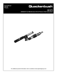
Service Manual
PL92-5000EN
03/10/2010
158QRA & 158/15QRA Series
Adaptive Positive Feed Drill
For additional product information visit our website at
http://www.cooperpowertools.com
Quackenbush®
PL92-5000EN
Model Nomenclature
XXX
Q
R
A
- XXX -
Tool Series
158 = Positive Feed
158/15 = Positive Feed
Brand
Q = Quackenbush
Tool Style
R = Right Angle
Revision
A = Adaptive Drill
RPM (Spindle Speed)
Select Desired Speed
900 / 300 (158 series)
12/4 = 1200 / 400 (158/15 series)
Feed Rate
Select desired feed rate
10 = .001 IPR
20 = .002 IPR
Spindle Length
A = Length (Specify 0.00) (Stroke+Non-Thread+Gear Head)
F = No Spindle
Spindle Interface Thread to Cutter
A = 1/4-28
B = 5/16-18
C = 3/8-24
D = 9/16-18
E = Other (specify)
Nose Attachment Thread
A = 2 1/4-20 (158 series)
B = 1 9/16-20 (158 series)
C = 1.0"-20 (158/15 series)
Options
2 = Concentric Collet
4 = Indexer
5 = None
Accessories
A = Nose
B = Spindle
C = Chuck
D = Fluid Chuck
E = Fluid Inducer
F = None
Last three digits of material number
Page 3
XX
- 9.50
03/10/2010
X
X
-
X
XXX - XXX
Quackenbush®
PL92-5000EN
General Safety & Tool Operation
03/10/2010
General Safety Instructions:
These safety instructions must be accessible to the
operator at all times. They must be shown and made
available to all personnel involved in the use of this
equipment.
These safety instructions are not intended to be all
inclusive. Study and comply with all applicable Federal,
State and Local Regulations. If necessary, contact your
local Cooper Tools’ representative for assistance.
Always disconnect the tool from the air supply
before adjusting or repairing.
Immediaely shut off the tool in the case of unusual
sound or vibration. Have a qualified person check the
tool and repair before using.
Do not modify the tool, any guard or accessory unless
approved in writing by Cooper Tools.
Implement and follow a Safety Maintenence Program to
provide inspection and maintenance of all phases of
tool operation and air supply equipment.
Eye Protection:
Do not wear loose fitting clothes,
long hair, gloves, ties or jewelry.
The spindle on right angle positive feed drills retracts at
a much faster rate than it feeds. Care must be taken to
avoid entrapment.
Nosepieces usually used with these drills are generally
slotted for visibility and access to chuck, cutter, and
retract stop adjustments. A spindle guard should be
used when operating the tool.
Spindle guards in one inch increments are available to
accommodate any length spindle. Slotted spindle
guards are available for tools with fluid swivels.
Impact resistant eye protection
must be worn while operating
or working near this tool.
Personal hearing protection is
recommended when operating
or working near this tool.
Hearing Protection:
Hearing protection is recommended in high noise
areas, 85 dBA or greater. The operation of other tools
and equipment in the area, reflective surfaces, process
noises and resonant structures can substantially
contribute to and increase the noise level in the area.
General Protection:
Follow good machine shop practices. Rotating shafts
and moving components can entangle or entrap and
may result in serious personal injuries. Never wear long
hair, loose fitting clothes, gloves, ties or jewelry when
working with or near a drill of any type.
Page 4
Keep hands and fingers away from
slot in spindle guard and nosepiece
when handling or operating tool.
Quackenbush®
PL92-5000EN
General Safety & Tool Operation
Respirator:
Wear respirator where necessary.
Drilling or other use of this tool may produce hazardous
fumes and/or dust. To avoid adverse health effects
utilize adequate ventiliation and wear a respirator if
necessary. Read the Material Safety Data Sheet
(MSDS) for any cutting fluids or materials involved in
the drilling process.
●
●
●
●
Most dusts are combustable. See Material Safety
Data Sheets for combustibility of a specific dust.
Non ferrous metal dusts are particularly hazardous.
Examples: Aluminum, Magnesium, Titanium
(Never collect Magnesium in a dry dust collector.)
Never collect spark generating material in the same
dust collector with combustible material.
Examples: Steel and Aluminum dust or Steel and
Titanium dust
Never use flamable finishing lubricants.
03/10/2010
158-15 Gear Head: The feed mechanism is engaged by
pushing the feed/retract lever (622973) down.
The spindle will automatically retract when the stop
collar depresses the retract lever. The spindle may be
manually retracted at any stage by pulling up on the
retract lever. The tool must be shut off when the spindle
is completely retracted.
158-15 Gear Head: The Gear Stop (622985) can be
adjusted by turning the two 1/8” hex set screws
(867502) on either side of the angle head.
Always disconnect the tool from it’s air supply
before installing or removing a cutter and other
accessories or performing any maintenance.
Before mounting any positive feed drill, check the lock
screws in the tooling fixture and drill bushing. Make sure
both are in good condition and securely tightened.
Positive feed drills can exert high torques and high
thrust loads. If failure of the lock screws or drill bushing
occurs, the drill may suddenly spin and back away from
the drill fixture.
Figure 1
Lock Screws
Tool Nose
Tool Operation:
This tool is designed to drill holes in different material
stacks and is for use only with the Quackenbush DMP
control box and should not be connected directly to a
standard air line.
Refer to PL92-DMP for operation and use of the DMP
control box, these instructions must be read and
understood before initiating any drilling operation.
The operating parameters for the tool are programmed
using the adaptive interface kit and DMP-TMS
programming software, refer to literature PL92-DMPPROG for details on programming the tool memory,
these instructions must be read and understood before
initiating any drilling operation.
The power unit is started by turning the throttle valve
lever.
158 Gear Head: The feed mechanism is engaged by
depressing the feed cam knob while the tool is running.
Standard Threaded Drill Bushing
Tooling Fixture
Warning Labels:
The warning labels on these tools are essential parts of
the product and are not to be removed. Check labels
regularly and replace any that are not clearly legible.
The Nosepiece safety label number is 202691.
Storage:
If it is necessary to store this tool for an extended period
of time (overnight, weekend, etc.), it should receive a
generous amount of lubricant at that time and again
when returned to service. Always store the tool in a
clean dry environment.
Page 5
PL92-5000EN
03/10/2010
Quackenbush®
Service Instructions
General Instructions:
Torque Specifications for Fasteners:
Basic engineering practice should be used when
assembling threaded components. Tightening torque
values are shown on the exploded views as a guide for
disassembly and re-assembly. The “Hand” image
indicates “Hand Tighten”.
Disassembly:
Remove all external tubing from the unit. Secure the
tool in a smooth jawed vise by clamping lightly on the
motor housing flats. Loosen the lock ring and unthread
the drill head assembly (RH thread) from the power unit.
158-15 Series: The drill head assembly utilizes a motor
adapter for assembly to the power unit.
Gearing:
Refer to Illustration “C”.
Disassembly:
Remove the lock ring from the internal gear. Using a
suitable wrench, unthread the internal gear (RH thread)
from the motor housing. The planet cage assembly can
now be removed from the internal gear and the
component parts disassembled.
158 Series: Unthread the bevel gear (RH thread) from
the planet cage to permit disassembly of the front planet
cage ball bearing and washer.
thread) and remove the handle assembly from the
motor housing. The complete motor assembly can now
be removed through the rear of the motor housing.
Unthread the magnet rotor (LH thread) from the motor
shaft to permit disassembly of the rear bearing plate
and bearing.
Using a soft mallet, tap the motor shaft out of the front
ball bearing. This will allow the disassembly of the front
bearing plate, cylinder, rotor blades and rotor.
To remove the ball bearing from the front bearing plate,
unthread the bearing retainer (LH thread) from the front
bearing plate.
Assembly:
The rotor blades should be replaced during each
maintenance cycle or if they are worn 1/16” below the
rotor surface, Figure 3.
Assembly Note: The beveled edge of the blade is the
trailing edge. The rotor and cylinder have an “R” etched
on one end. The “R” should be facing the rear to insure
clockwise rotation, Figure 3.
Figure 3
1/16” Maximum
Assembly:
Apply a generous amount of No. 2 Moly grease to all
gearing components during assembly.
Assembly Note: Assemble the tang end of the planet
gear pins toward the front of the planet cage so the
planet cage washer will lock them in position, Figure 2.
Rotor Blade
Beveled Edge
is Trailing Edge
158 Drill Head:
Figure 2
Refer to Illustrations “D” & “E”.
Planet Gear Pin
tang
Disassembly:
Planet Cage
Motor Module:
Refer to Illustrations “A” & “B”.
Disassembly:
“R”
Toward
Air Inlet
To remove the motor assembly from the motor housing
invert the tool in the vise. Unthread the handle nut (RH
Remove the stop body assembly (4 screws) from the
drill head housing.
Loosen the two set screws in the side of the housing
and remove the gear stop.
Remove the cylinder assembly (3 screws) from the drill
head housing.
Remove the housing cover (3 screws) from the drill
head housing. The gearing components can now be
disassembled as shown in Illustration “E”.
Page 6
Quackenbush®
Service Instructions
Assembly:
Assemble the drill head in reverse order of disassembly.
Clean and inspect all parts for excessive wear or
damage and replace as necessary with Quackenbush
replacement parts.
Apply a generous amount of Acculube grease to all
gears and bearings during assembly.
Assembly Note: Always install the spindle from the drive
gear side of the drill head housing, Figure 4.
Figure 4
PL92-5000EN
03/10/2010
distorted. Now rotate the two set screws counterclockwise 90-180 degrees. With this method, it is easier
to determine when the spring makes up solid so there is
less tendency to force the screw in to deep causing
damage to the spring.
Method 2 (fully assembled unit): The clutch rollers are
normally sitting in the detents. Turn the two set screws,
in the side of the housing, clockwise until the springs
just begin to go solid. Care must be taken not to distort
the springs. Once the solid state is achieved, rotate the
set screws counter-clockwise 2-1/4 full turns plus 90180 degrees. Important: Too much tension can
result in gear damage.
158-15 Drill Head:
Refer to Illustrations “F” & “G”.
Disassembly:
Install spindle from
this direction only.
The 158 series drill head does not require shims to set
the bevel gears. Correct engagement of the bevel gears
is obtained by running the power unit at a very slow
speed and threading it into the drill head until gear
interference is felt. Back off the power unit
approximately 1/8” turn or until there is no gear
interference then tighten the lock nut. This procedure
will attain maximum gear engagement.
After the tool is assembled, place a few drops of 10W
machine oil in the air inlet befoe attaching the air supply.
This will insure immediate lubrication of all parts as
soon as air is applied.
Gear Stop Adjustment:
There are two methods that can be used to adjust the
gear stop. The preferred method is to make the
adjustment during assembly of the drill before the
retract body and it’s related components are attached to
the drill head, see Method 1.
Method 1 (during assembly): Place the gear stop in
position with the two clutch rollers located on top of the
cam lobes, rather than in the detents. Turn the two set
screws, in the side of the housing, clockwise until the
springs begin to make up solid but are not crushed or
Unthread the motor adapter (LH thread) from the drill
head housing. Remove the hex drive adapter, drive
coupling, spacer, bearing, and bevel gear from the drill
head housing.
Remove the retract body assembly (4 screws) from the
drill head housing.
If used, unthread the upper jam nut (LH thread) from the
spindle. Loosen the set screw in the side of the upper
stop collar and unthread the stop collar (LH thread) from
the spindle.
Unthread the nose adpater (LH thread) from the drill
head housing. The spindle assembly can now be
removed from the drill head housing.
Remove the cover (2 screws) from the drill head
housing. The gearing components can now be
disassembled as shown in Illustration “G”.
Assembly:
Assemble the drill head in reverse order of disassembly.
Clean and inspect all parts for excessive wear or
damage and replace as necessary with Quackenbush
replacement parts.
Apply a generous amount of Acculube grease to all
gears and bearings during assembly.
Assembly Note: When installing the 617168 ball
bearing, make sure the ball loading notches are facing
the drill head housing.
Assembly Note: Always install the spindle from the drive
gear side of the drill head housing, Figure 4.
Page 7
Quackenbush®
PL92-5000EN
Handle & Sensor Assemblies
03/10/2010
“A”
20
35-45 ft. lbs.
19
18
16
2 in. lbs.
15
16
14
10
9
Ref.
3
13
12
17
1
11
6
1
7
8
6
2
3
5
Hand Tighten: RH Thread
Page 8
4
Quackenbush®
Handle & Sensor Assemblies
Illustration "A" - Handle Assembly
Ref
Number
#
-1
2
3
4
5
6
7
8
9
10
11
12
13
14
15
16
17
18
19
20
642014PT
642015PT
613254
1466
613697
844111
843434
624121
812962
613253
812231
843656
1853
613102
613282
613283
642013PT
504970
622332
202932
633753PT
1
1
1
2
1
1
2
1
1
1
1
1
1
1
1
1
1
1
2
4
1
X
6
1
2
2
3
3
3
3
1
3
2
4
EN
Description
Handle Assembly (includes Ref. 1 - 15)
Throttle Handle
Valve Assembly
O-Ring
Trigger
Dowel Pin
Pressure Plug
Gasket
Screw (10-32 UNF)
Washer
Retaining Ring
Air Screen
Shim
Hose Adapter
Clamp Ring
Handle Nut
Sensor Assembly (includes Ref. 16 - 20)
O-Ring
Screw (4-40 UNC)
Screw (4-40 UNC)
Protection Cap
(#) Quantity
(X) Recommended Spare Parts
Page 9
PL92-5000EN
03/10/2010
Quackenbush®
PL92-5000EN
Motor Module
03/10/2010
“B”
642011PT Motor Module
18
17
16
15
12
5
14
13
7
11
10
8
4
3
4
2
1
Page 10
6
9
Quackenbush®
PL92-5000EN
Motor Module
03/10/2010
Illustration "B" - Motor Module
Ref
Number
#
-1
2
3
4
5
-6
7
8
9
10
11
12
13
14
15
16
17
18
641660
615391
615467
613275
844265
633608PT
641662
613294
613248
613273
617609
613225
613162
617608
863365
613234
613236
613241
847511
633728PT
1
1
1
1
2
1
1
1
1
1
1
1
1
1
2
1
4
1
1
1
X
2
6
2
2
1
2
4
8
2
1
EN
Description
Motor Housing Assembly (includes Ref. 1 - 5)
Exhaust Deflector
Wire Screen
Motor Housing
Ball (.125")
Muffler
Motor Assembly (includes Ref. 6 - 17)
Bearing Retainer
Front Ball Bearing
Front Bearing Plate
Pinion Gear
Cylinder
Pin
Motor Shaft
Woodruff Key
Rotor
Rotor Blade
Rear Bearing Plate
Rear Ball Bearing
Magnet Rotor
(#) Quantity
(X) Recommended Spare Parts
Page 11
Quackenbush®
PL92-5000EN
Gearing Assembly
03/10/2010
“C”
621251 Gearing Assembly
9
6
7
8
4
5
3
2
1
Page 12
Quackenbush®
PL92-5000EN
Gearing Assembly
03/10/2010
Illustration "C" - Gearing Assembly
Ref
Number
#
1
2
3
4
5
6
7
8
9
619421
613285
864471
617370
612050
617305
613271
613279
613281
1
1
1
1
1
3
6
3
1
EN
X
2
6
12
6
2
Description
Lock Nut
Internal Gear
Ball Bearing
Planet Cage Washer
Planet Cage
Planet Gear
Needle Bearing
Planet Pin
Ball Bearing
(#) Quantity
(X) Recommended Spare Parts
Page 13
Quackenbush®
PL92-5000EN
158 Right Angle Drill Head - Housing
03/10/2010
“D”
23
4 in. lbs.
19
28
22
25
16
20
24
18
26
23
24
15*
6 in. lbs.
10
12
4
Nylok
Hand Tighten: RH Thread
14*
27
5
Nylok
21
23
13
6
4
17*
3
2
11
7
8
1
3
2
* Note: Not included in Drill Head Assembly
Page 14
9
Quackenbush®
158 Right Angle Drill Head - Housing
Illustration "D" - Right Angle Drill Head - Housing (158 series)
Ref
Number
#
-1
2
3
4
5
6
7
8
9
10
11
12
13
14
15
16
17
18
19
20
21
22
23
24
25
26
27
28
Table "D"
624622
624615
624916
202583
613828
834228
617246
617257
843280
624106
864287
617249
617245
613365
617243
619830
Table "D1"
842160
617247
884125
617252
842515
882209
882407
617395
833075
842161
617396
1
1
2
2
2
1
2
1
2
2
1
1
1
4
1
1
1
1
1
1
1
1
1
3
2
1
1
1
2
EN
X
4
6
4
6
4
2
4
2
3
3
2
2
3
3
2
3
2
Description
Drill Head Assembly
Housing
Clutch Plunger
Clutch Adjustment Spring
Set Screw (5/16-18 UNC)
Nameplate
Drive Screw
Cam
Cam Spring
Dowel Pin (Cam)
Stop Body
Dowel Pin (Trigger)
Knob
Screw
Stop Collar
Screw (8-32 UNC)
Spring
Spindle Guard and Fluid Inducer
Steel Ball (7/32")
Trigger
Lever Pin
Trigger Plunger
Reverse Stop Spring
Tubing Elbow
Air Line
Valve Body
Push Rod
Steel Ball (3/16")
Screw (6-32 UNC)
(#) Quantity
(X) Recommended Spare Parts
Table "D"
Ref.
Description
#
Part Number
Feed Rate
---
Drill Head Assembly
Drill Head Assembly
1
1
621915
621916
.001
.002
Table "D1"
Ref.
Description
#
Spindle Guard
Spindle Guard
Spindle Guard
Spindle Guard
Spindle Guard
Spindle Guard
Spindle Guard
1
1
1
1
1
1
1
Number
624360
624361
624362
624103
624363
624104
Solid Guard
Length
Fluid Inducer
1"
2"
3"
4"
641947PT
5"
6"
Variable Solid Guard
Number
Length
Fluid Inducer
641983-7
7"
641983-8
8"
641983-9
9"
641983-10
10"
641947PT
641983-11
11"
641983-12
12"
641983PT
13"
17
Spindle Guard
Fluid Inducer
Page 15
Number
624375
624376
624322
624377
624323
624376
Fluid Guard
Length
Fluid Inducer
2"
3"
4"
5"
621448
6"
7"
PL92-5000EN
03/10/2010
PL92-5000EN
03/10/2010
Quackenbush®
158 Right Angle Drill Head - Gearing
“E”
8
N
N
5
4
3
6
7
10 in. lbs.
1
27
28
29
22
31
14
23
15
24
30
16
25
32
17
25
18
26
* Note: Not included in Drill Head
Assembly.
Hand Tighten: RH Thread
11
21
12
13
34
35
WARNING: Spindle wrench (45) is
used to hold the spindle when
removing cutters. The air supply
must be disconnected from the tool
before the spindle wrench is used.
Note: Always replace Bevel Gear
and Bevel Pinion in pairs since
both should wear equally.
10
20
33
15 in. lbs.
9
19
21
N
2
38
36
39
37
42
Install Spindle
from this
direction.
40
7 in. lbs.
1-9/16” Thread (standard)
2-1/4”-20 Thread Adapter (Optional) - 614228
41
Page 16
43*
44*
1-1/8”
8.00”
45*
Quackenbush®
158 Right Angle Drill Head - Gearing
Illustration "E" - Right Angle Drill Head - Gearing (158 series)
Ref
Number
#
-1
2
3
4
5
6
Table "E"
Illustration "D"
624617
617253
624620
615433
624614
614269
614270
614216
617220
Table "E1"
617200
624635
624638
842161
617391
616479
Table "E2"
617217
617198
619377
843390
613687
619017
613686
619019
617208
843179
864471
614217
617203
863365
847095
624636
847688
624619
624616
847272
844303
624618
882209
624651
Table "E3"
613365
617243
622466
1
1
2
1
1
1
2
AR
AR
1
1
1
1
1
1
1
1
4
1
1
1
1
2
1
1
1
2
1
1
1
1
1
1
1
1
3
1
1
1
1
1
1
3
1
1
1
1
7
8
9
10
11
12
13
14
15
16
17
18
19
20
21
22
23
24
25
26
27
28
29
30
31
32
33
34
35
36
37
38
39
40
41
42
43
44
45
EN
X
4
2
4
AR
AR
1
2
1
1
2
3
1
2
1
2
2
1
4
2
2
1
3
2
6
3
3
2
6
2
Description
Drill Head Assembly
Housing
Screw (6-32 UNC)
Needle Bearing
Gear Stop
Thrust Race
Clutch Roller
Shim (.005")
Shim (.010")
Bevel Pinion
Ball Bearing
Spindle Feed Gear
Spindle Drive Gear
Ball Bearing
Thrust Race
Steel Ball (3/16")
Cam Follower
Pin
Differential Feed Gear
Retaining Ring
Drive Gear
Ball Bearing
Gear Spacer
Idler Gear Spacer
Retaining Ring
Idler Gear
Ball Bearing
Idler Shaft
Retaining Ring
Ball Bearing
Bevel Gear
Pinion Gear
Woodruff Key
Ball Bearing
Housing Cover
Screw (10-24 UNC)
Feed Gear Bushing
Piston
O-Ring
O-Ring
Cylinder
Tubing Elbow
Screw (6-32 UNC)
Spindle
Stop Collar
Set Screw (8-32 UNC)
Spindle Wrench
(#) Quantity
(X) Recommended Spare Parts
Page 17
PL92-5000EN
03/10/2010
PL92-5000EN
03/10/2010
Quackenbush®
158 Right Angle Drill Head - Gearing
Blank Page
Page 18
Quackenbush®
PL92-5000EN
158 Right Angle Drill Head - Gearing
03/10/2010
Table "E"
Ref.
Description
#
Part Number
Feed Rate
---
Drill Head Assembly
Drill Head Assembly
1
1
621915
621916
.001
.002
Table "E1" - Spindle Feed Gear
Ref.
10
Description
#
Part Number
Spindle Feed Gear
Spindle Feed Gear
1
1
615893
615894
Feed per
Revolution
.001
.002
Number of
Teeth
50
44
Feed per
Revolution
.001
.002
Number of
Teeth
49
44
Table "E2" - Differential Feed Gear
Ref.
17
Description
Differential Feed Gear
Differential Feed Gear
#
Part Number
1
1
624643
617356
Table "E3" - Spindles
Part
Number
Spindle
1
615890
Spindle
1
623211
Spindle
1
623955
42
Spindle
1
623210
Spindle
1
633179
Spindle
1
615982
Note: Other spindles avilable on request.
Ref.
Description
#
Page 19
Overall
Length
7.00"
8.50"
9.25"
10.00"
12.00"
15.00"
Solid or
Fluid
Fluid
Fluid
Fluid
Fluid
Fluid
Fluid
Attachment
Thread
9/16"-18
3/8"-24
9/16"-18
9/16"-18
9/16"-18
5/8"-18
PL92-5000EN
03/10/2010
Quackenbush®
158/15 Right Angle Drill Head - Housing
“F”
23
10 in. lbs.
12
20-30 ft.. lbs.
9
Nylok
Nylok
21
19
20
16
10
7
22
17
11
8
18
6
5
6
15
5
4
Page 20
13
4
2
1
Hand Tighten: RH Thread
14
3
Quackenbush®
158/15 Right Angle Drill Head - Housing
PL92-5000EN
03/10/2010
Illustration "F" - Right Angle Drill Head - Housing (158/15 series)
Ref
Number
#
-1
2
3
4
5
6
7
8
9
10
11
12
13
14
15
16
17
18
19
20
21
22
23
24
Table "F"
622986
613828
834228
622984
619685
867502
Illustration "G"
Illustration "G"
617149
622951
625625
625626
624094
844111
844787
622954
62973
863337
617962
617785
629545
624351
Table "F1"
624355
1
1
1
2
2
2
2
1
1
1
1
1
1
1
1
1
1
1
4
1
1
1
1
1
1
X
4
6
6
6
2
2
2
4
2
2
EN
Description
Drill Head Assembly
Housing
Nameplate
Drive Screw
Clutch Roller
Clutch Adjustment Spring
Set Screw (1/4-20 UNC)
Bevel Gear (Driving)
Ball Bearing
Spacer
Drive Coupling
Hex Drive Adapter
Motor Adapter
Retract Body
Lever Pin
Roll Pin
Ball Plunger (5/16-18 UNC)
Retract Lever
Screw (6-32 UNC)
Stop Collar
Set Screw (8-32 UNC)
Jam Nut (Optional)
Spindle Guard Shim (Fluid Spindle Guard only)
Spindle Guard and Fluid Inducer
Spindle Guard Cap
(#) Quantity
(X) Recommended Spare Parts
Table "F"
Ref.
Description
#
Part Number
Feed Rate
---
Drill Head Assembly
Drill Head Assembly
1
1
631778
631780
.001
.002
Table "F1"
Ref.
Description
#
Spindle Guard
Spindle Guard
Spindle Guard
Spindle Guard
Spindle Guard
Spindle Guard
Spindle Guard
1
1
1
1
1
1
1
Number
624339
624340
624341
624095
624342
624096
Solid Guard
Length
Fluid Inducer
1"
2"
3"
4"
641948PT
5"
6"
Variable Solid Guard
Number
Length
Fluid Inducer
641984-7
7"
641984-8
8"
641984-9
9"
641984-10
10"
641948PT
641984-11
11"
641984-12
12"
641984PT
13"
23
Spindle Guard
Fluid Inducer
Page 21
Number
624328
624329
624330
624331
624332
624333
Fluid Guard
Length
Fluid Inducer
2"
3"
4"
5"
631256
6"
7"
Quackenbush®
PL92-5000EN
158/15 Right Angle Drill Head - Gearing
03/10/2010
“G”
5
4
N
3
2
1
26
5
N
27
32
6
Nylok
28
29
33
17
27
21
30
18
19
31
20
24
25
10 in. lbs.
N
Note: Always replace the Bevel
Gears in pairs since both should
wear equally.
* Note: Not included in Drill Head
Assembly.
Hand Tighten: RH Thread
7
8
9
10
11
WARNING: Spindle wrench (34) is
used to hold the spindle when
removing cutters. The air supply
must be disconnected from the tool
before the spindle wrench is used.
12
21
22
23
15 in. lbs.
Page 22
1-1/8”
34*
13
14*
15*
16*
8.00”
Quackenbush®
158/15 Right Angle Drill Head - Gearing
Illustration "G" - Right Angle Drill Head - Gearing (158/15 series)
Ref
Number
#
-1
2
3
4
5
6
7
8
9
10
11
12
13
14
15
16
17
18
19
20
21
22
23
24
25
26
27
28
29
30
31
32
33
34
Table "G"
Illustration "F"
622985
622984
622947
847095
863463
617168
Table "G1"
622950
622400
865576
622401
Table "G2"
617962
617785
629545
Table "G3"
617993
842161
622949
847609
844306
622976
625092
617166
614574
619016
617980
622948
614575
622980
622946
622952
622466
1
1
1
2
1
2
1
1
1
1
1
1
1
1
1
1
1
1
1
1
1
1
1
1
1
2
1
2
1
1
1
1
1
1
1
EN
X
4
1
4
3
2
1
1
2
2
1
3
3
1
2
3
1
4
2
2
1
1
1
Description
Drill Head Assembly
Housing
Gear Stop
Clutch Roller
Bevel Gear (Driving)
Ball Bearing
Screw (6-32 UNC)
Ball Bearing
Spindle Feed Gear
Spindle Drive Gear
Ball Bearing
Thrust Race
Nose Adapter
Spindle
Stop Collar
Set Screw (8-32 UNC)
Jam Nut (Optional)
Differential Feed Gear
Spring
Steel Ball (3/16")
Differential Drive Gear
Ball Bearing (Pinion Shaft)
O-Ring
Drive Gear Retainer Screw (8-32 UNC)
Cover
Screw (6-32 UNC)
Idler Gear Spacer (Long)
Retaining Ring
Ball Bearing
Idler Gear
Idler Gear Spacer (Short)
Idler Gear Shaft
Bevel Gear (Driven)
Pinion and Shaft
Spindle Wrench
(#) Quantity
(X) Recommended Spare Parts
Table "G"
Ref.
Description
#
Part Number
Feed Rate
---
Drill Head Assembly
Drill Head Assembly
1
1
631778
631780
.001
.002
Page 23
PL92-5000EN
03/10/2010
PL92-5000EN
03/10/2010
Quackenbush®
158/15 Right Angle Drill Head - Gearing
Table "G1" - Spindle Feed Gear
Ref.
8
Description
#
Part Number
Spindle Feed Gear
Spindle Feed Gear
1
1
623002
622943
Feed per
Revolution
.001
.002
Number of
Teeth
43
40
Table "G2" - Spindles
Part
Number
Spindle
1
615915
Spindle
1
624083
Spindle
1
623812
13
Spindle
1
623284
Spindle
1
627467
Note: Other spindles avilable on request.
Ref.
Description
#
Overall
Length
4.00"
5.00"
6.00"
9.00"
10.00"
Solid or
Fluid
Fluid
Fluid
Fluid
Fluid
Fluid
Attachment
Thread
3/8"-24
1/4"-28
3/8"-24
5/16"-24
9/16"-18
Table "G3" - Differential Feed Gear
Ref.
17
Description
Differential Feed Gear
Differential Feed Gear
#
Part Number
1
1
623003
622945
Feed per
Revolution
.001
.002
Page 24
Number of
Teeth
40
38
Sales & Service Centers
Note: All locations may not service all products. Please contact the nearest Sales & Service Center for the
appropriate facility to handle your service requirements.
Dallas, TX
Cooper Tools
Sales & Service Center
1470 Post & Paddock
Grand Prairie, TX 75050
Tel: 972-641-9563
Fax: 972-641-9674
Lexington, SC
Cooper Tools
670 Industrial Drive
Lexington, SC 29072
Tel: 800-845-5629
Tel: 803-359-1200
Fax: 803-358-7681
York, PA
Cooper Tools
Sales & Service Center
3990 East Market Street
York, PA 17402
Tel: 717-755-2933
Fax: 717-757-5063
Detroit, MI
Cooper Tools
Sales & Service Center
2630 Superior Court
Auburn Hills, MI 48326
Tel: 248-391-3700
Fax: 248-391-7824
Los Angeles, CA
Cooper Tools
Sales & Service Center
15503 Blackburn Ave
Norwalk, CA 90650
Tel: 562-926-0810
Fax: 562-802-1718
Canada
Cooper Tools
Sales & Service Center
5925 McLaughlin Road
Mississauga, Ont. L5R 1B8
Canada
Tel: 905-501-4785
Fax: 905-501-4786
Houston, TX
Cooper Tools
Sales & Service Center
6550 West Sam Houston
Parkway North, Suite 200
Houston, TX 77041
Tel: 713-849-2364
Fax: 713-849-2047
Seattle, WA
Cooper Tools
Sales & Service Center
2865 152nd Ave N.E.
Redmond, WA 98052
Tel: 425-497-0476
Fax: 425-497-0496
Cooper Tools
P.O. Box 1410
Lexington, SC 29071-1410
USA
Phone: 800-845-5629
803-359-1200
Fax:
803-359-0822
Cooper Tools
5925 McLaughlin Road
Mississauga, Ontario
Canada L5R 1B8
Phone: 905-501-4785
Fax:
905-501-4786
Cooper Tools
2630 Superior Court
Auburn Hills, MI 48326
Phone: 248-391-3700
888-332-6061
Fax:
248-391-7824
Cooper Tools
de México S.A. de C.V.
Libramiento La Joya No. 1
Bodega No. 2
Esq. Politécnico
Barrio San José
Cuautitlán, Edo de México
C.P. 54870
Phone: +52-55-5899-9510
Fax:
+52-55-5870-5012
Cooper Tools Industrial
Ltda.
Av. Liberdade, 4055
Zona Industrial - Iporanga
18087-170 Sorocaba, SP
Brazil
Tel: +55-15-3238-3929
Fax: +55-15-228-3260
Cooper Power Tools SAS
Zone industrielle – B.P. 28
77831 Ozoir-la-Ferrière
Cedex
France
Téléphone: +33-1-6443-2200
Téléfax:
+33-1-6440-1717
Westhausen, EMEA
Cooper Power Tools
GmbH & Co. OHG
Postfach 30
D-73461 Westhausen
Germany
Phone: +49 (0) 73 63/ 81-0
Fax: +49 (0) 73 63/ 81-222
HTWE.sales
@cooperindustries.com
Coventry, UK
Cooper Power Tools
GmbH & Co. OHG
Unit G Quinn Close
Seven Stars Industrial Estate
Whitlet
Coventry CV3 4LH
UK
Phone: +44-2476-3089 60
Fax:
+44-2476-3089 69
Cooper Power Tools
GmbH & Co. OHG
Postfach 30
D-73461 Westhausen
Germany
Phone: +49 (0) 73 63/ 81-0
Fax: +49 (0) 73 63/ 81-222
HTWE.sales
@cooperindustries.com
Cooper (China) Co., Ltd.
955 Sheng Li Road,
Heqing Pudong, Shanghai
China 201201
Tel: +86-21-28994176
+86-21-28994177
Fax: + 86-21-51118446
www.coopertools.com
Cooper Tools
1000 Lufkin Road
Apex, NC 27539
Phone: 919-387-0099
Fax:
919-387-2614
www.coopertools.com
PL92-5000EN/Printed in USA 03/2010/Copyright © 2010 Cooper Industries