1
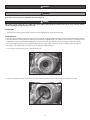
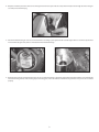
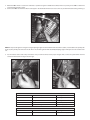
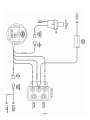
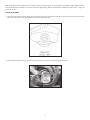
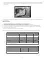
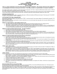
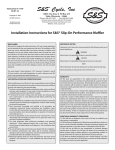
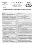
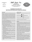
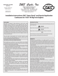
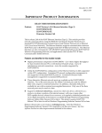
3-30-10
S&S Cycle, Inc
Copyright © 2007, 2010
by S&S® Cycle, Inc.
Phone: 608-627-1497 • Fax: 608-627-1488
Instruction 51-1206
®
.
All rights reserved.
Printed in the U.S.A.
14025 Cty Hwy G, PO Box 215
Viola, Wisconsin 54664
Technical Service Phone: 608-627-TECH (8324)
Technical Service Email: [email protected]
Website: www.sscycle.com
Installation Instructions for S&S® Super Stock Ignition
DISCLAIMER:
S&S parts are designed for high performance, closed course, racing
applications and are intended for the very experienced rider only. The
installation of S&S parts may void or adversely affect your factory warranty.
In addition such installation and use may violate certain federal, state, and
local laws, rules and ordinances as well as other laws when used on motor
vehicles used on public highways, especially in states where pollution laws
may apply. Always check federal, state, and local laws before modifying your
motorcycle. It is the sole and exclusive responsibility of the user to determine
the suitability of the product for his or her use, and the user shall assume all
legal, personal injury risk and liability and all other obligations, duties, and
risks associated therewith.
The words Harley®, Harley-Davidson®, H-D®, Sportster®, Evolution®, and all
H-D part numbers and model designations are used in reference only. S&S
Cycle is not associated with Harley-Davidson, Inc.
SAFE INSTALLATION AND OPERATION RULES:
Before installing your new S&S part it is your responsibility to read and follow
the installation and maintenance procedures in these instructions and follow
the basic rules below for your personal safety.
Gasoline is extremely flammable and explosive under certain conditions
and toxic when breathed. Do not smoke. Perform installation in a well
ventilated area away from open flames or sparks.
If motorcycle has been running, wait until engine and exhaust pipes
have cooled down to avoid getting burned before performing any
installation steps.
Before performing any installation steps disconnect battery to eliminate
potential sparks and inadvertent engagement of starter while working
on electrical components.
Read instructions thoroughly and carefully so all procedures are
completely understood before performing any installation steps.
Contact S&S with any questions you may have if any steps are unclear or
any abnormalities occur during installation or operation of motorcycle
with a S&S part on it.
Consult an appropriate service manual for your motorcycle for correct
disassembly and reassembly procedures for any parts that need to be
removed to facilitate installation.
Use good judgment when performing installation and operating
motorcycle. Good judgment begins with a clear head. Don’t let
alcohol, drugs or fatigue impair your judgment. Start installation
when you are fresh.
Be sure all federal, state and local laws are obeyed with the installation.
For optimum performance and safety and to minimize potential
damage to carb or other components, use all mounting hardware that is
provided and follow all installation instructions.
Motorcycle exhaust fumes are toxic and poisonous and must not be
breathed. Run motorcycle in a well ventilated area where fumes can
dissipate.
••
••
••
••
••
••
••
••
••
IMPORTANT NOTICE:
Statements in this instruction sheet preceded by the following words are of
special significance.
WARNING
Means there is the possibility of injury to yourself or others.
CAUTION
Means there is the possibility of damage to the part or motorcycle.
NOTE
Other information of particular importance has been placed in italic type.
S&S recommends you take special notice of these items.
WARRANTY:
All S&S parts are guaranteed to the original purchaser to be free of
manufacturing defects in materials and workmanship for a period of twelve
(12) months from the date of purchase. Merchandise that fails to conform to
these conditions will be repaired or replaced at S&S’s option if the parts are
returned to us by the purchaser within the 12 month warranty period or within
10 days thereafter.
In the event warranty service is required, the original purchaser must call or
write S&S immediately with the problem. Some problems can be rectified by
a telephone call and need no further course of action.
A part that is suspect of being defective must not be replaced by a Dealer
without prior authorization from S&S. If it is deemed necessary for S&S to
make an evaluation to determine whether the part was defective, a return
authorization number must be obtained from S&S. The parts must be packaged
properly so as to not cause further damage and be returned prepaid to S&S
with a copy of the original invoice of purchase and a detailed letter outlining
the nature of the problem, how the part was used and the circumstances at
the time of failure. If after an evaluation has been made by S&S and the part
was found to be defective, repair, replacement or refund will be granted.
ADDITIONAL WARRANTY PROVISIONS:
(1) S&S shall have no obligation in the event an S&S part is modified by any
other person or organization.
(2) S&S shall have no obligation if an S&S part becomes defective in whole or in
part as a result of improper installation, improper maintenance, improper use,
abnormal operation, or any other misuse or mistreatment of the S&S part.
(3) S&S shall not be liable for any consequential or incidental damages
resulting from the failure of an S&S part, the breach of any warranties, the
failure to deliver, delay in delivery, delivery in non-conforming condition, or
for any other breach of contract or duty between S&S and a customer.
(4) S&S parts are designed exclusively for use in Harley-Davidson® and other
American v-twin motorcycles. S&S shall have no warranty or liability obligation
if an S&S part is used in any other application.
DANGER
Disconnect the battery of your motorcycle before attempting this installation.
WARNING
Electrical connections are required to complete this installation. If you are unsure of your abilities to make these connections safely,
please take your motorcycle to a qualified shop for the installation.
DANGER
This ignition system requires the use of VOES switch. If the VOES is inadvertently grounded, it will create an excess advance situation
which could damage the engine in your motorcycle.
INstallation
1- Preparation: Turn off the ignition switch and disconnect the negative battery cable before proceeding.
IMPORTANT NOTES:
•• If your ignition was installed at the factory in a complete engine assembly, do not adjust the module. Breaking the tamper resistant seal will void your warranty.
•• Factory installed Super Stock® ignitions have a break-in rev limit feature. It will gradually raise the rev-limit over the first 24 hours of running time from
4300 RPM to the maximum of 6300 RPM. Avoid dangerous situations that could require full power maneuvers during this initial break-in period.
•• The Super Stock ignition module comes pre-programmed from S&S® for a specific engine size and style. You cannot modify the ignition timing curve.
•• If your ignition was installed at S&S in a complete engine assembly, you should start at step 6.
2- You should be starting from this point–an empty timing cavity.
Picture 1
3- Install the included timing cup and screw. Be sure to put some blue threadlock on the screw and tighten securely (15-20 in-lbs).
Picture 2
2
4- Wrap the end of the protective sleeve on the wiring harness with one layer of electrical tape. This will help slide it through the hole in the gear
case and protect it from fraying.
Picture 3
5- Place the module into the gear case area and route the wires according to your application. On cast S&S engines there is a channel to lay the wires
in and on billet S&S gearcovers, there is a hole that the wires must feed through.
Picture 4
Picture 5
6- Route the wiring harness along the frame to the coil. You can route the wires for a generator engine behind the pushrod tubes or to the frame. Be
sure that the wiring harness is not touching any hot or moving parts. Secure the harness to the frame using wire-ties once you are sure it is routed
properly.
3
7- Mount the VOES switch as close to the carburetor as possible using the included bracket. Note: There is no polarity on the VOES so either wire
can be used for ground or signal.
8- Connect the VOES hose from the switch to the nipple in the manifold. Trim the hose to be as short as possible without stretching or kinking it.
Picture 6
NOTE: The Super Stock® ignition is a single-fire design requiring a single fire coil with a minimum of 3.0 ohms resistance, measured across the primary side
of the coil. (The primary side of the coil is the side where wires from the ignition will be attached). Dual-plug engines will require two coils or a four-tower
coil.
9- You will need to make some crimp connections once you trim the wires to their proper lengths. Then, to wire the system follow the wire
connection table below and Figure A to the right.
Picture 8
Picture 7
Ignition Module
White/Black
Switched 12-volt power
Small ring terminal
Pink
Front cylinder on coil
Small ring terminal
Blue
Rear cylinder on coil
Small ring terminal
Violet/White
VOES
Tab assembly (male)
Brown
Tachometer/Diagnostic Port
Tab assembly (male)
VOES SWITCH
Black
Ground
Large ring terminal
Black
Ignition module
Receptacle assembly (female)
4
WIRING DIAGRAM
(Using two coils for dual plug engines)
Figure A
5
Figure B
6
NOTE: If your ignition was installed at S&S® in a complete engine assembly, timing was set at the factory. Do not adjust timing. Breaking the tamper
resistant seal will void your warranty. You can now connect the negative battery, and are finished with the installation procedure. Please see page 7 for
general system notes.
SETTING STATIC TIMING
1- You will need to remove the timing plug from the crankcase. Remove the spark plugs and rotate the motor until you bring the front piston to
TDC on the compression stroke. Look for the mark shown in the picture below.
Figure C
2- Use test plugs or jumper wires to ground the spark plug wires. Then connect the negative battery cable again.
Picture 8
7
3- Turn on the ignition switch and confirm the engine cut off switch is in the run position. Rotate the ignition module back and forth SLOWLY
until the red LED turns on. Once the light is on, rotate the module CLOCKWISE until the light just goes out. The light goes out when the
module is at TDC.
Picture 8
4- Use blue threadlock and tighten the standoffs (12-20 in-lbs) to secure the module in its proper timing position. Turn the ignition off and put
the spark plugs in.
GENERAL SYSTEM NOTES:
1-
2-
3-
4-
5-
6-
7-
The S&S® Super Stock® Ignition requires the use of a 3 OHM single-fire coil like the S&S coil PN 55-1571.
S&S recommends spiral core spark plug wires. Do not use solid copper or non-resistor plug wires.
S&S recommends Champion RN12YC (14mm) or Champion RA8HC (12mm) spark plugs gapped at .038” to .042”.
The VOES must be installed and wired for proper installation. When the VOES is activated, the green LED light in the module will illuminate.
Dealer software for engine diagnostics is available through the S&S website, www.sscycle.com or through your customer service representative.
S&S recommends using 91 or higher octane fuel.
Ignition systems for shovelhead style S&S engines are kick start compatible.
These charts may be used to ensure your module is correct for the application, and may be used to order replacement modules and kits.
S&S® SUPER STOCK® IGNITION KITS AND REPLACEMENT PARTS FOR S&S AFTERMARKET® ENGINES
Application
Factory Module
Replacement Module
Ignition Kit*
S&S 80” Alternator/Generator shovelhead
55-1240B
55-1240
55-1250
S&S 93” Alternator/Generator shovelhead
55-1241B
55-1241
55-1251
S&S 93” HC Alternator/Generator shovelhead
55-1242B
55-1242
55-1252
S&S 103” Alternator/Generator shovelhead
55-1243B
55-1243
55-1253
S&S 96” V96
55-1244B
55-1244
55-1254
S&S 113” V113
55-1245B
55-1245
55-1255
S&S 124” V124
55-1246B
55-1246
55-1256
Kit contains S&S Super Stock module with hardware, pick-up cup and mounting screw, VOES switch with hardware, connectors and instructions. Replacement
modules do not have break-in rev limiter activated.
S&S® SUPER STOCK® REPLACEMENT MODULES FOR S&S EMISSIONS CERTIFIED ENGINES
Application
Factory Module
Replacement Module
S&S 3 /8” V-Series
55-1264B
55-1264
S&S 4” V-Series
55-1265B
55-1265
S&S 41/8” V-Series
55-1266B
55-1266
5
Replacement modules do not have break-in rev limiter activated.
8