1
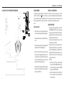
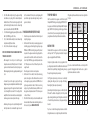
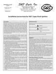
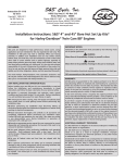
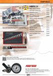
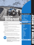
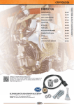
Owners Manual
S&S® V-Series Engines
DISCLAIMER:
S&S parts are designed for high performance, closed course, racing applications
and are intended for the very experienced rider only. The installation of S&S parts
may void or adversely effect your factory warranty. In addition such installation and
use may violate certain federal, state, and local laws, rules and ordinances as well
as other laws when used on motor vehicles used on public highways, especially in
states where pollution laws may apply. Always check federal, state, and local laws
before modifying your motorcycle. It is the sole and exclusive responsibility of the
user to determine the suitability of the product for his or her use, and the user shall
assume all legal, personal injury risk and liability and all other obligations, duties,
and risks associated therewith.
The words Harley®, Harley-Davidson®, H-D®, Sportster®, Evolution®, and all H-D
part numbers and model designations are used in reference only. S&S Cycle is not
associated with Harley-Davidson, Inc.
SAFE INSTALLATION AND OPERATION RULES:
Before installing your new S&S part it is your responsibility to read and follow the
installation and maintenance procedures in these instructions and follow the basic
rules below for your personal safety.
•• Gasoline is extremely flammable and explosive under certain conditions and
toxic when breathed. Do not smoke. Perform installation in a well ventilated
area away from open flames or sparks.
•• If motorcycle has been running, wait until engine and exhaust pipes have
cooled down to avoid getting burned before performing any installation steps.
•• Before performing any installation steps disconnect battery to eliminate
potential sparks and inadvertent engagement of starter while working on
electrical components.
•• Read instructions thoroughly and carefully so all procedures are completely
understood before performing any installation steps. Contact S&S with any
questions you may have if any steps are unclear or any abnormalities occur
during installation or operation of motorcycle with a S&S part on it.
•• Consult an appropriate service manual for your motorcycle for correct
disassembly and reassembly procedures for any parts that need to be removed
to facilitate installation.
•• Use good judgment when performing installation and operating motorcycle.
Good judgment begins with a clear head. Don’t let alcohol, drugs or fatigue
impair your judgment. Start installation when you are fresh.
•• Be sure all federal, state and local laws are obeyed with the installation.
•• For optimum performance and safety and to minimize potential damage to
carb or other components, use all mounting hardware that is provided and
follow all installation instructions.
Motorcycle exhaust fumes are toxic and poisonous and must not be breathed. Run
motorcycle in a well ventilated area where fumes can dissipate.
WARRANTY:
All S&S parts are guaranteed to the original purchaser to be free of manufacturing
defects in materials and workmanship for a period of twelve (12) months from the
date of purchase. Merchandise that fails to conform to these conditions will be
repaired or replaced at S&S’s option if the parts are returned to us by the purchaser
within the 12 month warranty period or within 10 days thereafter.
In the event warranty service is required, the original purchaser must call or write
S&S immediately with the problem. Some problems can be rectified by a telephone
call and need no further course of action.
A part that is suspect of being defective must not be replaced by a Dealer without
prior authorization from S&S. If it is deemed necessary for S&S to make an evaluation
to determine whether the part was defective, a return authorization number must
be obtained from S&S. The parts must be packaged properly so as to not cause
further damage and be returned prepaid to S&S with a copy of the original invoice
of purchase and a detailed letter outlining the nature of the problem, how the part
was used and the circumstances at the time of failure. If after an evaluation has been
made by S&S and the part was found to be defective, repair, replacement, or refund
will be granted.
OWNERS MANUAL — S&S® V-SERIES ENGINES
ADDITIONAL WARRANTY PROVISIONS:
(1) S&S shall have no obligation in the event an S&S part is modified by any other
person or organization.
(2) S&S shall have no obligation if an S&S part becomes defective in whole or in part
as a result of improper installation, improper maintenance, improper use, abnormal
operation, or any other misuse or mistreatment of the S&S part.
(3) S&S shall not be liable for any consequential or incidental damages resulting from
the failure of an S&S part, the breach of any warranties, the failure to deliver, delay in
delivery, delivery in non-conforming condition, or for any other breach of contract
or duty between S&S and a customer.
(4) S&S parts are designed exclusively for use in Harley-Davidson® and other
American v-twin motorcycles. S&S shall have no warranty or liability obligation if an
S&S part is used in any other application.
Table of Contents:
Introduction....................................................................................................... 2
Engine Installation................................................................................ 2
Oil Line Hook up............................................................................................ 2
Oil Recommendations................................................................................. 2
General Break-in Procedure...................................................................... 5
Tune Up Information............................................................................ 7
Super Stock & IST Ignition Systems........................................................ 7
EFI Information............................................................................................... 7
Starting Procedure........................................................................................ 8
Super E & G Carburetor Tuning Guide................................................... 9
Engine Service Intervals............................................................................ 12
Engine Specifications......................................................................... 13
Engine Dimensions.....................................................................................14
Torque Specifications................................................................................16
Specifications and Wear Limits.............................................................. 17
OWNERS MANUAL — S&S® V-SERIES ENGINES
INTRODUCTION
The S&S® engine you have purchased is an air-cooled, v-twin. It is
designed to offer Proven Performance® and reliability. Specifications
for the 31⁄2", 35⁄8", 4", and 41/8" bore engines are found in this manual.
We have covered the most popular configurations, 80ci, 96ci, 111ci,
and 124ci, based on their original S&S production designs. Some
changes may have been made over time as these engines have been in
production for a number of years. The specifications in this manual are
based on the most recent production specifications.
ENGINE INSTALLATION
The procedure for installing an S&S engine is basically the same as
outlined in the factory service manual for the model of motorcycle the
engine is being installed in. However, S&S engines are sometimes taller
then a stock engine so the installer must check to make sure there is
adequate clearance between the engine and all chassis components
including the frame and fuel tanks. An upgraded clutch should also be
considered, since the S&S engine will produce more power than the
stock engine it is replacing.
OIL LINE HOOK-UP
Viscosity
Ambient Temperature (°F)
SAE 20W50
Above 30°–100°
SAE 50
Above 60°–100°
SAE 25W60
Above 80°
SAE 60
Above 80°
OIL LINE HOOK-UP V-SERIES
OIL RECOMMENDATIONS
S&S recommends synthetic engine oil such as S&S Premium Synthetic
20W50. However a premium petroleum based engine oil such as S&S
Heavy Duty 20W50 or 25W60 is acceptable.
Regardless of what type of oil you select, be sure to use only oil
specifically designated for use in an air-cooled motorcycle, and
select the viscosity suggested for the temperature range you will be
operating your motorcycle in.
The oil filter used on an S&S® V-Series engine should be rated at 24
microns. Spin-on filters should not have an anti-drain back valve.
S&S filters are available to replace Harley-Davidson® #63805-80A and
63796-77A. The S&S part numbers are 31-4101 and 31-4102.
The following diagrams show how the crankcase breather and oil lines
should be hooked up for S&S V-Series engines. Note most 41/8" bore
engines have a use a vacuum breather system
2
3
OWNERS MANUAL — S&S® V-SERIES ENGINES
OIL LINE HOOK-UP FOR V-SERIES WITH VACUUM BREATHING
FUEL REQUIREMENTS
Either petroleum or synthetic oil designed for air-cooled v-twin
engines can be used during the break-in period and during normal use.
If preferred, petroleum oil can be used for the break-in period, after
which, the engine can be changed over to synthetic oil.
GENERAL BREAK-IN NOTES
1.
••
Remember that these are air-cooled engines. Sufficient air movement
is required to keep engine temperatures within safe operating limits.
••
Avoid heavy traffic and congestion or extended idle periods whenever
possible.
••
S&S v-twin performance engines are designed for, and happiest when
running between 2750-3500 at normal highway speeds.
••
Today’s heavier bikes and taller gearing can easily push a high
performance engine into a lugging condition which increases loads
on engine components, causes detonation, builds excessive heat, and
increases fuel consumption. If the engine does not accelerate easily
when given some throttle, downshift to a lower gear.
••
4
BREAK-IN OIL CONSIDERATIONS.
The gasoline used in your engine should have a US octane rating of 91
or higher. The United States uses the
method of octane rating. In
many countries outside the United States, the RON (Research Octane
Number) is used, which will result in a higher octane requirement of
about 96.
S&S engines benefit from a warm-up period any time they are started,
allow engine to reach operating temperature before being subjected
to heavy loads or quick throttle revs.
BREAK-IN PROCEDURE
2.
3.
4.
Initial start up. Run engine approximately one minute at 12501750 RPM. DO NOT crack throttle or subject to any loads during
this period as head gaskets are susceptible to failure at this time.
During this time, check to see that oil pressure is normal, that oil is
returning the oil tank, and that no leaks exist.
Shut off engine and thoroughly check for any leaks or other
problems. Let engine cool to the touch.
After engine has cooled, start up again and allow the motor to
build some heat. Engine should be run no longer than three to
four minutes. When the cylinders become warm/hot to the touch
(approximately 150°F) shut the motor down and let it cool to room
temp. Follow the same cautions as for the initial start-up, and
continue to check for problems.
First 50 Miles:
a. Street: Ride normally, do not lug the engine. Avoid high
heat conditions and vary the RPM while riding. No stop and
go traffic, extended idle periods, or high load or high RPM
conditions. Max of 3,500 RPM or 60 MPH.
b. Dyno: A chassis dynamometer can be used to put the first 50
miles on a new engine. See the notes and procedure below
for chassis dyno break-in.
5
OWNERS MANUAL — S&S® V-SERIES ENGINES
5.
6.
7.
8.
50–100 Miles: Ride normally, do not lug the engine. Avoid high
heat conditions, no stop and go traffic or extended idle periods.
Limited short bursts of throttle can aid in ring seating from this
point forward during the break-in, but avoid continuous high
speed or load conditions. Max of 4,250 RPM/70 MPH.
100–500 Miles: Avoid lugging the engine and high heat conditions.
Max of 5,000 RPM. Change oil at 500 miles.
500–1,000 miles: Ride bike normally, but avoid continuous high
load operation and high heat conditions.
From 1,000 miles on: Break-in is complete, enjoy!
street for a minimum of 500 miles prior to completing tuning at full
power. Monitor engine temperature during tuning to ensure the
engine is not overheated.
DYNO BREAK-IN PROCEDURE (FIRST 50 MILES)
1.
2.
NOTES FOR COMPLETING INITIAL 50 MILE BREAK-IN AND INITIAL
TUNING ON A CHASSIS DYNO
••
••
••
6
When running the bike on the dyno it is critical that engine
temperatures are monitored, AFR is kept between 12.5–14.7 and the
engine is not overheated. Fans must be used to keep the engine cool.
When tuning under higher loads stop regularly and allow the engine
to cool.
A load must be placed on the engine to properly seat the rings.
Running a new engine continually with no load will result in cylinder
glazing and poor ring seal. The engine should be loaded to simulate
close to the weight of the bike, a load of 10–15% on a Dyno jet 250i is
usually sufficient. It is not recommended to use an inertia only dyno to
break-in an engine as no load can be placed on the engine.
Initial tuning on the engine can be completed during the initial 50
miles of dyno break-in. It is recommended the engine be run on the
3.
4.
5.
Follow the same procedure outlined above for initial start-up and
heat cycling the engine.
Run the bike for 25 miles on the dyno under varying speeds and
loads while going up and down through the gears. Keep engine
RPM below 3,500 RPM but do not lug the engine. The dyno must
be operated so the engine runs under a load roughly equal to the
power needed to move the bike down the road, this would be
about 12 hp at 55 MPH. Keep engine head temperatures below
200°F at the temp sensor or surface of the head. Stop and cool the
engine if needed.
Allow the engine to cool down to room temperature.
Run the bike for 25 more miles (50 miles total) under varying
speeds, loads, and gears as before. Make sure there is some load
on the engine. Keep engine speed below 4,250 RPM but do not
lug the engine. Limited short bursts of throttle can aid in ring
seating as long as the calibration/tune keeps the AFR in control.
Keep engine head temperatures below 225°F at the temp sensor
or surface of the head.
After the first 50 miles on the dyno, it is recommended the normal
break-in schedule be followed under normal riding conditions on
the street. See Step 5 under BREAK-IN PROCEDURE.
TUNE UP INFORMATION
S&S 4" bore and smaller V-Series engines come from the factory with
Champion RN12YC 14mm long reach spark plugs (S&S PN 55-1321). 4-1/8"
bore engines come from the factory with Champion RA8HC 12mm spark
plugs (S&S PN 55-1320). All spark plugs should be gapped between
.038- and .042-inch. If you are not using an S&S ignition system, refer to
your ignition manufacturer for any additional recommendations.
IGNITION SYSTEM
Carbureted S&S V-Series engines come from the factory with either
an S&S Super Stock™ or IST® ignition system installed. Fuel injected
engines are equipped with an S&S VFI module.
S&S Super Stock ignition modules are factory programmed for the
specific engine they are intended for. In addition the module is installed
and timed to S&S specified timing. Changing the timing or removing
the Super Stock ignition may void your warranty.
S&S IST ignition systems employ a knock sensor to automatically
optimize ignition timing and protect your engine from damage.
Removing the IST ignition may void your warranty.
Ignition timing in S&S fuel injected engines, is controlled by the S&S
VFI module. The calibration file supplied by S&S for the particular
engine contains ignition timing curves. If the ignition curve is modified
or if another fuel injection module is used, the engine warranty may
be voided.
If you choose to install another ignition system, make sure that the
total ignition advance is set according to the specifications in this chart.
If the ignition system has a rev limiter, make sure it is set no higher than
6200 rpm..
Engine
Total Advance,
Max Advance,
VOES Grounded Wide Open
(deg BTDC)*
Throttle (WOT)
RPM Max
Advance
@ WOT
V124
34°
29°
5000
V117
35°
30°
5000
V113
34°
29°
5000
V111
35°
31°
5000
V96
32°
27°
5000
V80
35°
33°
5000
If you choose to install another EFI module on a fuel injected V124
engine, the following ignition table should be used as a guide for
ignition advance under various conditions
EFI Ignition Table - S&S V124, 10.8:1 CR, 640 Cam
RPM
1000
2000
3000
4000
5000
6000
WOT
5.0°
15.4°
18.2°
19.5°
22.3°
26.0°
Cruise
16.0°
25.0°
34.1°
34.0°
31.7°
30.0°
Idle/Decel
15.5°
20.4°
34.4°
40.0°
42.3°
42.3°
7
OWNERS MANUAL — S&S® V-SERIES ENGINES
START-UP — ENGINES EQUIPPED WITH S&S SUPER E
OR G CARBURETOR
1.
2.
3.
4.
5.
6.
7.
S&S Super E & G carburetors have a mixture enrichment/fast idle
lever used to aide in cold starts and help during the warm-up
period. Do not ride the motorcycle with the lever engaged.
Turn the fuel supply valve on, wait a moment to make sure the
carburetor bowl is full, and twist the throttle twice to prime the
carburetor—starting in extremely cold weather may require
additional priming.
Pull the fast idle lever up, turn on the ignition and press the start
button or kick the engine through.
If the engine does not start after several kicks or five seconds of
cranking, shut the ignition off for 15 seconds to let the starter cool.
Open the throttle slightly and press the starter button or kick the
engine through again. It may be necessary to re-prime the engine.
If the engine kicks back, the throttle may be opened too far.
Once the engine is running, use the fast idle lever to maintain the
proper engine speed required during warm-up.
When the engine has warmed up enough to idle without the
enrichment system, disengage the fast idle lever. The fast idle
lever is not required to restart a hot engine.
3.
4.
5.
data from the knock sensor and other sensors.
Ride the motorcycle as you would normally, being sure to include
hills, highway speeds (for at least 20 minutes at a time) and around
town. Be sure to use the throttle in as many settings as possible—
without going past the suggested break-in procedures!
Once the engine is completely broken in, the IST will be tuned to
optimize the engine’s performance.
Do not run the engine on a dyno until the IST has had time to tune
itself to your engine.
START-UP – ENGINES EQUIPPED THE VARIABLE FUEL
INJECTION (VFI)
1.
2.
3.
Turn the ignition and kill switches on. Listen for the fuel pump as
it pressurizes.
Do not twist the throttle open to prime the system.
Press the starter button and let engine crank over—do not twist
the throttle. If the engine is extremely hard to start—hot or
cold—contact the S&S® Tech Line or visit www.sscycle.com for the
location of the closest VFI Tuning Center.
SUPER E & G CARBURETOR TUNING GUIDE
1.
2.
3.
4.
5.
6.
INITIAL START UP WITH IST IGNITION
1.
2.
8
Start the motorcycle up as outlined above.
The IST ignition comes with a general ignition map that will allow
the engine to be started and run. Within 3 to 5 hours of operation
the IST module will optimize this map for your engine, based on
7.
Verify carburetor is set to stock settings:
a. Idle mixture screw, 11/4 turns from lightly seated.
b. Idle speed screw, ½ turn clockwise from engagement point.
c. Accelerator adjustment screw, two turns counter-clockwise
from seated.
Start bike, bring to operating temperature.
Set idle speed adjusting screw, clockwise to increase RPM,
counter-clockwise to decrease RPM. Idle RPM range should be 950
to 1050 RPMs.
Adjust idle mixture by turning idle mixture screw slowly clockwise
until the engine runs poorly. Note position. Slowly turn the screw
counter-clockwise until it starts to stumble. Note position. Set
the idle mixture screw halfway between the positions, or at the
strongest idle. Inconsistent idle may indicate a manifold leak.
With engine idling, turn accelerator adjustment screw clockwise
until it lightly seats. Snap throttle open—engine should stumble.
Turn screw counter-clockwise ¼ or ½ of a turn at a time, until
engine responds to throttle twist with smooth, quick response.
Ride motorcycle in various RPM ranges, and then try to maintain
a consistent 40- to 50-MPH. If the engine has a flat spot, or
is popping/sneezing in the air cleaner, it can indicate a lean
condition. If you notice stumbling or sputtering, it can indicate a
rich condition.
Low RPM operation is controlled by the intermediate jet (#11 on
following page). If sneezing or popping is experienced below
approximately 3000 RPMs the intermediate jet must be replaced
with a larger sized (richer) jet. If the engine does not run smoothly
at low speeds, fouls plugs, blows black smoke or gets bad gas
mileage a smaller (leaner) intermediate jet needs to be installed.
Always readjust the idle mixture (#2) and idle speed (#1) screws
after making a jet change.
8. To test the main jet, do a roll-on from 50-MPH to 70-MPH in 3rd
gear. If the engine backfires or breaks up in the carb, increase
the main jet size .004". If the engine is flat or will not accelerate,
decrease the main jet by .004".
9. Since 2004 S&S shorty carbs have been fitted with an adjustable
main jet air bleed (#13). Changing this jet to a larger size will delay
the signal to the main jet, therefore aiding with high speed tuning
as described in step 8. This also aides with tuning an engine that
is fitted with an exhaust system that is not intended for high
performance. The air bleed uses main jets, the stock size is 40. If it
needs to be changed the range is normally 50 to 60.
10. NOTE: Drag or straight pipes, especially large diameter or long
designs, can prevent you from obtaining optimum carburetor
performance.
11. If the S&S teardrop air cleaner is being replaced with an aftermarket
air cleaner, be sure to remove the auxiliary bowl vent screw (#14).
Never use a velocity stack on a street driven motorcycle! Poor
throttle response will be experienced.
12. Always be sure to attach the hose to the overflow tube fitting (#6)
and route it toward the back of the engine.
9
OWNERS MANUAL — S&S® V-SERIES ENGINES
Approximate Jetting For S&S® Super E & G Carburetors
Displacement
883cc
74 – 88ci
96 – 107ci
111 – 124ci
Intermediate Jet
.265 – .028
.0295
.031
.031
Main Jet
.066
.072
.076
.078
13
8
These jetting recommendations are a starting point only. Re-jet carb for best
performance.
10
11
2
3
6
1
1- Idle Speed Screw
12
7
14
2- Idle Mixture Screw
3- Accelerator Pump Adjustment Screw
4- Enrichment Device
4
10
5- Serial Number
5
9
10- Accelerator Pump Pushrod
6- Overflow Tube Fitting
11- Intermediate Jet
7- Fuel Inlet
12- Main Jet
8- Bowl Vent Hole
13- Main Jet Air Bleed
9- Bowl Plug
14- Auxiliary Bowl Vent Plug
11
OWNERS MANUAL — S&S® V-SERIES ENGINES
ENGINE SERVICE INTERVALS
ENGINE SPECIFICATIONS
The following chart contains information about a number of S&S engines covered by this owners manual.
Item
Interval
Engine Oil & Filter
Change at 500, 2,500 miles (80, 800, 4,000 kilometers), every 2,500 miles (4,000 kilometers) thereafter1.
Engine
Displacement
Bore
Stroke
CR
Cam
Tappets
Fuel System
Air Cleaner Element
Inspect at 50 and 500 miles (80 and 800 kilometers), every 2,500 miles (4,000 kilometers) thereafter2.
Replace every 5,000 miles (8,000 kilometers).
Ignition
System
V80
80"
31/2"
41/4"
8.4:1
508
Hydraulic
Tappet Oil Screen
Inspect every 2,500 miles (4,000 kilometers). Replace every 5,000 miles (8,000 kilometers).
“Super E or
None”
“Super Stock
or None”
Petcock, Lines, & Fittings,
Vacuum Lines
Inspect at 50 and 500 miles (80 and 800 kilometers), every 2,500 miles (4,000 kilometers) thereafter.
V96
96"
35/8"
45/8"
9.5:1
585
“Hydraulic w/HL2T”
Super E
“Super Stock
or IST”
Fuel Tank Filter Screen &
In-Line Fuel Filter (If used)
Inspect every 5,000 miles (8,000 kilometers).
V96 TÜV
96"
35/8"
45/8"
10.1:1
520
“Hydraulic”
Super E
IST
V111
111"
41/8"
41/8"
9.8:1
585
“Hydraulic w/HL2T”
Super E
Engine Idle Speed
Adjust as required.
“Super Stock
or IST”
Operation of Throttle &
Enrichment Device Controls
Inspect at 500 miles (800 kilometers) and every 2,500 miles (4,000 kilometers) thereafter.
V113 TÜV
113"
4"
41/2"
10.1:1
547
“Hydraulic w/HL2T”
Super G
IST
V124
124"
41/8"
45/8"
10.8:1
640
“Hydraulic w/HL2T”
Super G or VFI
Spark Plugs
Inspect every 5,000 miles (8,000 kilometers). Replace every 10,000 miles (16,000 kilometers) or as needed.
“Super Stock,
IST, or VFI”
Ignition Timing
Inspect every 5,000 miles (8,000 kilometers).
V124 TÜV
124"
41/8"
45/8"
9.5:1
547
“Hydraulic w/HL2T”
Super G
IST
Engine Mounts
Inspect at 500 miles (800 kilometers) and every 5,000 miles (8,000 kilometers) thereafter.
External Fasteners Except
Engine Head Bolts
Re-torque at 500 miles (800 kilometers) and every 5,000 miles (8,000 kilometers) thereafter.
1- S&S recommends that petroleum-based oil not specifically formulated for motorcycles should be changed every 1,000 miles (1,600 kilometers)
after the break-in period.
2- Replace more frequently if required or if engine is operated in a dusty environment.
12
13
OWNERS MANUAL — S&S® V-SERIES ENGINES
ENGINE DIMENSIONS
IMPORTANT INFORMATION
Some S&S engines are taller than stock engines. These diagrams show the dimensions of various S&S engines. This information will be most
useful to customers building custom motorcycles with after market frames.
Engine
A
B
V80
V88
V96
V96 TUV
15.898"
15.736"
15.912"
15.912"
20.299"
20.165"
20.310"
20.310"
V100
15.623"
20.062"
V107
15.728"
20.163"
V113
V113 TUV
15.846"
15.846"
20.266"
20.266"
V124
15.979"
20.366"
V124 TUV
16.048"
20.424"
Nothing lasts forever, and despite the superior materials and design
of the components in your S&S engine, some day it will need to be
serviced. Who better to repair your engine, than the technicians at the
company where it was made? To obtain factory service for your S&S
engine, have your S&S dealer contact the S&S Service & Speed Center.
To find an S&S dealer in your area go to the S&S Dealer Locator at
www.sscycle.com/dealer-locator
••
S&S engines are not recommended for inexperienced riders
because the increased performance requires a higher level of
riding skill.
••
Do not lug your S&S engine. This is a high performance engine,
designed to produce excellent horsepower at higher RPM. It was
not well suited to pull heavy loads at low RPM. We recommend
that the engine not be operated below 2500 RPM for extended
periods of time. Shift to a lower gear to keep the engine speed up
when traveling at lower speeds.
••
Your S&S Engine is air cooled, which means that it depends on air
moving across the cooling fins to keep it from over heating. Do
not allow your engine to idle for extended periods of time. Avoid
stop and go traffic or any other situation where the motorcycle is
not moving while the engine is running.
••
To avoid engine damage, do not operate the engine above 6200
RPM.
SERVICE SPECIFICATIONS FOR S&S ENGINES
Front of Engine
14
CHARGING SYSTEM NOTE - If you are going to use a 45 amp alternator
you must install a S&S® spacer (PN 31-4033). If you do not use this spacer
the rotor could bottom out against the case when the sprocket shaft nut
is tightened.
For the most part if an S&S engine requires service, a qualified mechanic
who services Harley-Davidson® engines can do the work. However the
specifications for S&S engines are somewhat different. These charts
are provided for reference. For more detailed information about any
specific S&S component, installation instructions are available for free
download from the S&S website www.sscycle.com.
15
OWNERS MANUAL — S&S® V-SERIES ENGINES
SPECIFICATIONS & WEAR LIMITS
TORQUE SPECIFICATIONS
Item
Torque
Recommended
Item
Torque
Recommended
Rocker Box 1⁄4"
100-120 in-lbs
Loctite® 243
Compression releases
32-37 ft-lbs
Anti-seize
Rocker Box base 5⁄16"
15-18 ft-lbs
Loctite 243
Exhaust flange to head
15-18 ft-lbs
Anti-seize
Rocker arm support plate
15-18 ft-lbs
Loctite 243
Head temp sensor
10-12 ft-lbs
Anti-seize
Cylinder head bolts
8 ft-lbs, 18 ftlbs, 90°
Oil threads
Knock sensor
11 ft-lbs
Anti-seize
Cylinder studs
10 ft-lbs
Loctite 272
Crank position sensor
90-120 in-lbs
Crankcase fasteners
12-15 ft-lbs (1⁄4)
Spark plug
11-18 ft-lbs
NOTE: 12 in-lbs equals 1 ft-lbs
18-20 ft-lbs (5⁄16)
Piston oilers
25 in-lbs
Loctite 243
Pinion nut
50 ft-lbs
Loctite 272
Tappet guide fasteners
90-120 in-lbs
Loctite 243
Pushrod locknuts
90-120 in-lbs
Gear cover fasteners
100-120 in-lbs
Loctite 243
Timing hole plug
120 in-lbs
Anti-seize
Oil pump cover/mounting bolts (4) 90-120 in-lbs
Oil pump top mounting (2)
60 in-lbs
Intake manifold to head
16 ft-lbs
Loctite 243
Intake manifold to carb
18 ft-lbs
Loctite 243
16
Description
Specification
Wear Limit
Shaft in bushing
.0007"-.0018"
.0035"
Bushing fit in rocker arm (press)
.0012"-.0032"
<.0012"
.001"-.012"
Wear Limit
Side play
.006"-.036"
.040"
Wristpin in rod
.0005"-.001"
.002"
Crankpin running clearance
.001"-.0012"
.002"
Flywheels
Cylinder Head
Valve to guide fit intake
Anti-seize
Specification
Connecting Rods
Rocker Arm
Rocker arm endplay
Description
.0012"-.0020"
.0035"
Run out at bearing
.0005"-.001"
.006"
.001"-.005"
.005"
.0004"-.001"
.002"
Valve to guide fit exhaust
.0017"-.0025"
.0040"
Timken endplay
Valve guide in head (press)
.0015"-.0030"
<.0015"
Pinion bearing fit
Valve seat in head (press)
.0050"-.0070"
<.0050"
Cam Chest
Seat width intake
.031"
.041"
Breather gear endplay
.005"-.015"
.016"
Seat width exhaust
.047"
.057"
Breather clearance
.0015"-.003"
.004"
Valve stem protrusion
2.045"-2.060"
2.080"
Camshaft in bushing
.0007"-.002"
.0035"
Camshaft endplay
.005"-.015"
.016"
Pistons
Fit in cylinder
.002"-.0026"
.0055"
Pinion shaft in bushing
.001"-.0025"
.0035"
Compression ring gap
.017"-.026"
.030"
Bushing fit in gear cover (press)
.0007"-.0023"
<.0006"
Oil ring gap
.010"-.040"
.050"
Oil pump shaft
.0005"-.0025"
.0035"
.0006"-.0017"
.0022"
Lifters
Lifter fit in guide
17
OWNERS MANUAL — NOTES
S&S Cycle, Inc
®
.
14025 County Hwy G
Viola, WI 54664
Phone: 608-627-1497 • Fax: 608-627-1488
Technical Service Phone: 608-627-TECH (8324)
Technical Service Email: [email protected]
www.sscycle.com
510-0365
04/02/15
Copyright © 2015 by S&S® Cycle, Inc. All rights reserved. Printed in the U.S.A.