1
MODELS
4110 GL
4110 GLS
4110 GLSK
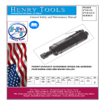
General Safety and Maintenance Manual 4110 GL+6
“FRONT” EXHAUST DIE GRINDER SERIES
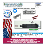
Front exhaust blows chips away from the operator.
Model
Number
4110GL
4110GLS
4110GL+6
Exhaust
Direction
Throttle
Type
FRONT
(L) Lever
or
(K) Safety
Lever
Speed
Power
Output
15000
0.9 H.P.
to
675 W
22000
R.P.M.
(22000RPM
is Standard)
Weight
Case
Material Aluminum Steel
Alum
1.5 lb
0.7 Kg
Length
Diameter
2.0
6.4 inch/ 1.6
lb/0.9 162 mm inches
Kg
41 mm
Air
Collet
ConsumpSize
tion
25cfm
1/4” (built-in
11.8 L/S
collet)
Steel
Steel
The Henry Tool Co., Manufactured by Henry Tools
498 So. Belvoir Blvd., South Euclid, OH 44121 U.S.A.
Ph: (216) 291-1011 or (800) 826-5257 ● Fax: (216) 291-5949 or (800) 303-2800
Email: [email protected] ● Website: www.Henrytools.com
Ph:
MODELS
4110 GL
4110 GLS
4110 GLSK
4110 GL+6
HENRY TOOLS, INC. (216) 291-1011 or (800) 826-5257
General Operators Instructions and Service Manual
www.HenryTools.com | Page 272
For additional product information visit our website.
Revised 07/07/15
DISASSEMBLY
1. Model 4110 with collet chuck- remove collet nut (400-G38) with 5/8 “ wrench and 7/16” wrench.
2. Clamp backhead [400-G-4(S)] in a vise. Using a strap
wrench, unscrew case (540098/540916). Tap lightly on
threaded end of spindle, this will allow the motor to drop out.
3. Remove snap ring(400-39) with type 01 pliers. Lift out
wafer (320-9W) and o-ring (If Present)(320-9R). Remove
snap ring (592016).
4. With brass or aluminum jawed vise, grasp the O.D. of the
cylinder and end plate (400-3) firmly. Use a 3/16” punch and
tap spindle out of rear bearing (400-9), being careful not to
drop spindle assembly when it is free.
5. Remove the rotor (400-5), blades (400-6), key (400-10)
and front thrust plate(400-7) .
6. Remove snap ring (400-46) with type 02 pliers. Place
bearing and spindle assembly (threaded end down) on suitable drill block. Press spindle through the bearing with an
arbor press.
7. To check throttle valve. unscrew plug (869311) and lift
out valve spring (400-G-34) and plunger (400-G-29). Remove
o-ring (400-G-31) and replace if cracked or worn.
REASSEMBLY
1. Support front bearing (400-G-ll) on suitable drill block.
Press spindle [400-G-14-CS] through bearing until it bottoms
on shoulder.
2. With type 02 pliers place the snap ring (400-46) into the
groove.
3. Slide on front thrust (400-7) over the arbor and on the
front bearing.
4. Place the key (400-10) into the slot in the spindle. Slide
rotor (400-5) over spindle, aligning the keyway in the rotor
with the key in spindle.
5. Place five blades (400-6) in slots of rotor. Slip cylinder
[400-2(G)] over rotor. Install rear thrust[400-3(A)]. (Carefully
locate cylinder in the smaller hole of the rear thrust.)
6. Place bearing in rear thrust adn tap bearing in with suitable bearing driver.
7. Place snap ring (592016) on spindle groove. If desired,
drop oring(320-9R) and washer (320-9W) in rear thrust. Place
snap ring(400-39) into groove.
8. Slip motor assembly in case (540098/540916.) Put backhead in vise and screw on motor housing. Tighten with a strap
wrench.
CAUTION: CHECK TOOL FOR SPEED WITH TACHOMETER.
THE SPEED STAMPED ON TOOL MUST BE AT OR ABOVE
THE ACTUAL SPEED OF THE TOOL.
Additional information on safety is available in the “American
National Safety Code for Portable Air Tools” (ANSI Bl86.1).
This bulletin is available from the American Standards Institute, Inc., 1430 Broadway, New York, N.Y. 10018.
4110GL SERVICE INSTRUCTIONS
Thls tool is designed to operate on 90 psig (6.2 bar) maximum air pressure with 1/4 (8 mm) hose.
SAFETY
1. Before operation check spindle speed with a tachometer. If the RPM’s exceed the rated speed stamped
on tool, servicing is required.
2. Inspect grinding wheels for bends, chips, nicks,
cracks or severe wear~ If the wheel has any of these,
or has been soaked in liquids do not use. On brushes
check for loose wires that may fly off in operation.
3. Start new grinding wheels under a steel bench.
Run at full throttle for one minute.
4. Defective wheels usually come apart immediately.
5. When starting a cold wheel apply to the work
slowly, allow wheel to warm up gradually.
6. The 4110 die grinders are intended for use with
mounted wheels, points and carbide burrs. They are
not guarded for type 1 wheels. If you have a type
1 wheel application, please purchase a wheel guard
(4503,4504).
7. At least one-half of the mandrel length (i.e.
mounted wheel, burr, etc.) must be inserted into the
collet. Secure collet chuck tightly.
8. Safety levers are available from the manufacturer
(402-26).
9. Before mounting or removing a wheel disconnect
grinder from air supply. The wheel should fit properly
on arbor; do not use bushings or wheel flanges to
adapt a wheel to any arbor unless recommended by
manufacturer.(Wheel flanges should be at least 1/3 the
diameter of the grinding wheel.)
10. Wear safety goggles and other protective clothing
(when necessary).(See regulations.)
11. Properly maintained air tools are less likely to
fail or cause accidents. If tool vibrates or produces an
unusual sound, repair immediately.
LUBRICATION
1. An air line filter-regulator-lubricator should be
located as closely as possible to the tool.
2. Clean out dirt and moisture fron air hoses daily.
Keep screen handle bushing in tool.
3. OIL TOOLS DAILY. Exxon’s Spinesstic 10, Atlantic
Richfield’s Duro 55, Gulf’s Gulfspin 10 or an equivalent
is reco~mended. Pour about 1 tablespoon in air inlet
and run tool to allow oil to be carried to the interior.
Do not use any wheel for which the operating speed
listed is lower than the actualfree speed on the
grinder.
Revised 07/07/15
www.HenryTools.com | Page 273
For additional product information visit our website.
Ph:
4410G Series grinder featres a Front exhaust that blows chips away from the
operator.
MODELS
4110 GL
4110 GLS
4110 GLSK
4110 GL+6
HENRY TOOLS, INC. (216) 291-1011 or (800) 826-5257
General Operators Instructions and Service Manual
4410G Series grinder featres a Front exhaust that blows chips away from the
operator.
Part Number
Description
Part Number
Description
400-2-G(w/400-44)
Cylinder with pin
ACCESSORIES
400-3
Rear End Plate
1100-063
5/8 Wrench
400-5
Rotor
1100-044
7/16” Wrench
400-6
Blade(5 req’d)
510075
Repair Kit(See 5000-40G Kit below)
400-7
Front Thrust
4503
3” Guard
400-9
Rear Bearing
4504
4” Guard
320-9-W
Rear Wafer(Optional)
320-9R
O-Ring(Optional)
400-G-4
Aluminum Backhead
400-G-4-S
Steel Backhead
400-46
Snap Ring
400-39
Snap Ring
400-10
Key
400-44
Pin
400-51
O-Rlng
400-G-17
Alum.Exhst Sleeve
400-G-17-S
Steel Exhst Sleeve
400-G-11
Bearing
400-G-14-CS
Collet Shaft
400-G-14-CS+3”
Extended shaft 3”
400-G-14-CS+6”
Extended shaft 6”
400-G-38
Collet Nut
400-G-31
O-Ring
400-G-26
Valve Lever
400-G-29
Throttle Valve
400-G-34
Spring
400-S-38
Aluminum Cap
400-S-38-S
700-37
832636
T.V. Cap Gasket
540098
Case (aluminum)
540916
Steel Case
540129
Cap
841553
Bushing
869311
T. Valve Cap
402-126
Lever (Bare)
402-127
Pin
402-128
Latch
402-129
Spring
402-26
Entire Safety Lever Assembly
REPAIR KIT
510075
Includes
1
400-G-11 Bearing
1
400-46 Snap Ring
1
400-9 Bearing
1
400-39 Snap Ring
1
832636 Gasket
5
400-6 Rotor Blades
FAULT
CAUSE
SOLUTION
Air pressure too
low
Minimum air pressure
should be 90 PSI for
maximum performance
Restriction in air
hose
Remove bends or other
restrictions
Hose I.D. is too
small
Use required hose I.D.
Steel Cap
Worn vanes
Exchange vanes (400-6)
Roll Pin
Screen Support
clogged
Clean screen support or
exchange with new one
No air, shut-off
valve is closed.
Open shut-off valve
Worn vanes
due to lack of
oil or vanes are
jammed
Exchange vanes .
(cylinder might also be
worn out)
Grinder does
not want to
stop
Worn O-Ring
Replace o-ring in handle
(844302) for example.
Spindle
wobbles or
vibrates.
Bearings worn
Disconnect tool from the
air supply. Immediate
servicing is required.
Insufficient
Power
Machine does
not start
out .
Danger!!
www.HenryTools.com | Page 274
For additional product information visit our website.
Revised 07/07/15
Ph:
MODELS
4110 GL
4110 GLS
4110 GLSK
4110 GL+6
HENRY TOOLS, INC. (216) 291-1011 or (800) 826-5257
General Operators Instructions and Service Manual